1
IUNION SWITCH & SIGNAL lrni)
645 Russell Street
Batesburg, SC 29006
SERVICE MANUAL 3623
KP RELAY
Description, Installation and Maintenance
May,1985
© 1985, Union Switch & Signal Inc.
Printed in U.S.A.
An Ansaldo Signal Company
m
UNION SWITCH & SIGNAL
REVISION INDEX
Revised pages of this manual are listed below
by page number and date of revision.
25
5/85
UNION SWITCH & SIGNAL
Contents
Section
I
II
GENERAL INFORMATION.
1
1.1
1.2
1.3
1
1
2
•
7
GENERAL.
MOUNTING BASE.
RELAY INDEXING.
RECEPTACLE SPRINGS.
RELAY INSERTION.
7
7
7
7
•
FIELD MAINTENANCE.
3.1
3.2
3.3
3.4
IV.
INTRODUCTION.
DESCRIPTION.
SPECIFICATIONS.
INSTALLATION.
2.1
2.2
2.3
2.4
2.5
III.
Page
4.1
4.2
4.3
4.4
4.5
4.6
4.7
4.8
4.9
APPENDIX A
9
INTRODUCTION.
•
SERVICE REQUIREMENTS.
CLEANING.
PERIODIC PERFORMANCE TEST.
SHOP MAINTENANCE.
9
•
9
•
9
9
13
•
INTRODUCTION.
CLEANING.
INSPECTION.
TEST EQUIPMENT.
TESTS AND CHECKS.
REPAIRS AND REPLACEMENT.
ADJUSTMENTS
CALIBRATION •
OPERATIONAL TEST.
PARTS LIST
8
•
13
13
13
13
13
14
19
23
29
m
UNION SWITCH 8i SIGNAL
SAFETY SUMMARY
Safety precautions that must be observed when performing certain tests
are cross-referenced by test and paragraph number.
The specific
IWARNING I
is placed prior to the performance of a particular step in a test.
TEST
PARAGRAPH NO.
When performing maintenance tasks, no
additional safety precautions are required,
other than common safety practices.
UNION SWITCH & SIGNAL
ffi
SECTION I
GENERAL INFORMATION
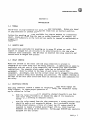
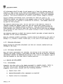
1.1
INTRODUCTION
This service manual provides service information for style KP relays. The style
KP designation includes a group of direct current two position polar-type
relays. The fundamental design, physical dimensions, and general appearances of
this entire group are identical, but the basic adjustments, contact combinations,
coil resistances, and calibration values are furnished in various combinations
for different applications. Because of the special fixtures required in the
assembly of these relays, it is recommended that they be returned to the factory
when major repairs involving replacement of parts are required. However, where
facilities are available to handle major repairs, reference should be made to
that particular section covered in this service manual.
1.2
1.2.1
DESCRIPTION
General
All KP relays are individually housed in molded bakelite cases with all operating
parts fully enclosed and sealed. All contacts are visible through the front
cover glass. The contact members are molded permanently in bakelite.
By means of basic magnetic adjustments made during manufacture, either of two
different types of relays operation are provided, namely "stick" or "biased".
The armature of a stick type relay is operated into alternate positions
(clockwise or counterclockwise) by opposite polarities, and remains in the last
operated position when the coils are deenergized.
The armature of a biased type relay is operated clockwise (closing the front
contacts) by normal polarity, and returns to the counterclockwise or "biased"
position (opening the front contacts) when deenergized. Since the armature
remains in the counterclockwise position when reverse polarity is applied, the
biased relay functions as a sensitive biased relay.
Basic magnetic adjustments, in combination with various contact assemblies, also
govern the wattage requirements of individual relays. It will be noted from the
calibration tables that the operating levels range from approximately 150 to as
low as 5 milliwatts.
3623 P• 1
m
UNION SWITCH & SIGNAL
1.2.2
Coils
KP relays have two coils which may be used either independently or in combination
to suit requirements.
In addition, any given relay of either stick or biased type of fixed wattage can
be furnished in a range of coil resistance from a fraction of an ohm to
approximately 4,000 ohms per coil to provide for various circuit requirements.
1.2.3
Contacts
Contacts are permanently molded in bakelite and are visible through the front
cover glass. The contact arrangements available provide for a multiple of
circuit applications.
1.3
SPECIFICATIONS
The following paragraphs provide the electrical and mechanical specifications of
the KP relays covered in this manual.
1.3.1
Electrical
Relay electrical specifications are tabulated in the following paragraphs.
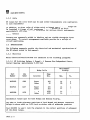
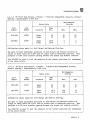
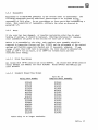
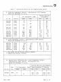
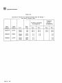
1.3.1.1 KP Stick Type Relays, 4 Normal - 4 Reverse Non-Independent Contact,
Contact Opening - Approximately 0.050 Inch
Milliamperes
Pick-Up
Relay Coils
Part
Number
Code
Number
Nl91493
45680
Upper
Lower
N217122
12347
N191500
45780
Location
Ohms
Res.
Max.
Min.
105
20
45
90
25
55
Upper
Lower
105
105
45
45
25
25
Upper
Lower
1070
1070
14
14
9
9
Calibration values apply for both Normal and Reverse Pick-Up.
The make or break adjustment positions of both Normal and Reverse contacts of
relays in above table are 0.025 inch on either side of midstroke position.
Tool N243001 is used to lock the armature in the correct positions of adjustment
of the above relays.
3623 P• 2
UNION SWITCH & SIGNAL
m
1.3.1.2 KP Stick Type Relays, 2 Normal - 2 Reverse Independent Contacts, Contact
Opening - Approximately 0.040 Inch
Milliamperes
Pick-Up
Relay Coils
Part
Number
Code
Number
Nl91499
45789
Upper
Lower
N220821
56780
Upper
Lower
Location
Ohms
Res.
Max.
Min.
20
20
30
30
20
20
1070
1070
5
5
3
3
Calibration values apply for both Normal and Reverse Pick-Ups.
The make or break adjustment positions of both Nonna! and Reverse contacts of
relays in above table are 0.005 inch on either side of midstroke position. This
provides a 0.010 inch transfer opening between the normal and reverse contacts.
Tool N243002 is used to lock the armature in the correct positions for adjustment
of the above relays.
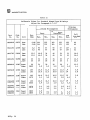
1.3.1.3 KP Stick Type Relays, 4 Normal - 4 Reverse Non-Independent Contact,
Contact Opening - Approximately 0.026 Inch
Milliamperes
Pick-Up
Relay Coils
Part
Number
Code
Number
N347480
12457
Upper
Lower
20
20
N371940
12458
Upper
Lower
12.5
12.5
Location
Ohms
Res.
Max.
Min.
92
92
57
57
120
120
74
74
Calibration values apply for both Normal and Reverse Pick-Ups.
The make or break adjustment positions of both Normal and Reverse contacts of
relays in above table are 0.015 inch on either side of midstroke position. This
provides a 0.030 inch transfer opening between the normal and reverse contacts.
Tool N347547 is used to lock the armature in the correct positions for adjustment
of the above relays.
3623 P• 3
m
UNION SWITCH & SIGNAL
1.3.1.4 Special KP Stick Type Relays (With Off-Center Adjustment), 2 Normal - 2
Reverse Independent Contacts, Contact Opening - Approximately 0.040 Inch
Pick-Up Milliamperes
Normal
(Clockwise)
Relay Coils
Part
Number
Code
Number
N231412
12357
Location
Upper
Lower
Reverse
(Counterclockwise)
Ohms
Res.
Max.
Min.
Max.
75
20.0
29.4
15.0
21.6
12.6
18.9
33
Min.
9.4
13.1
This relay is normally calibrated by first giving it the same mechanical contact
adjustments as the standard stick type relay with 2N-2R independent contacts.
Then the 0.005 inch off-center make or break adjustments slightly altered in
order to increase the normal pick-up and decrease the reverse pick-up until the
above specification is met.
When recalibrating the above type of relay, only sufficient alteration or
correction of contact adjustments should be made to directly reproduce the above
calibration without going through the basic procedure.
3623 P• 4
UNION SWITCH & SIGNAL
m
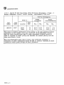
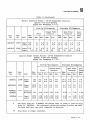
1.3.1.5 KP Biased Type Relays, 2 Normal - 2 Back Independent Contacts, Contact
Opening - Approximately 0.030 Inch
Relay Coils
Milliamperes
Pick-Up
Part
Number
Code
Number
Location
N225785
23456
Upper
Lower
12.5
12.5
N294846
12367
Upper
Lower
20
3800
35
25
3
2
Upper
Lower
105
17
17
9
105
Upper
Lower
105
1070
17
5.3
N215618
N296500
12348
12379
Ohms
Res.
Max.
50
50
Min.
30
30
Working
Max.
Full
Drop-Away
Min.
55
55
15
15
45
3.7
10
1
20
20
5
5
3.7
20
6.5
5
1.7
9
9
Nl91481
57890
Upper
Lower
1070
1070
5.3
5.3
3.7
3.7
6.5
6.5
1.7
1.7
N240096
12340
Upper
Lower
3800
3800
3
3
2
2
3.7
3.7
1
1
The make or break adjustement position of all four contacts of relays in the
above table is the midstroke position of the armature.
With armature in midstroke position, all four contacts should be just on the
point of making.
If there is more than approximately 0.001 inch opening (just a visible gap), it
should be reduced until the gap is barely visible. This adjustment should be
produced on all four contacts.
In no case should either front contact close before both back contacts open.
They should either just make at the same point or be slightly open.
Tool N243000 is used to lock the armature in the mid-position for adjustment of
the above relays.
m
UNION SWITCH 6 SIGNAL
1.3.2 Mechanical
The following mechanical specifications are common to all KP relays covered in
this manual.
UNION SWITCH & SIGNAL
m
SECTION II
INSTALLATION
2.1
GENERAL
The KP relay is plug-connected for quick and easy replacement. Relays are keyed
to plug connectors to prevent plugging the relay into an incorrect position.
Various size mounting racks are available for plug-in mounting on a horizontal
shelf. Relays are wired from the rear on solder terminals. The relay(s) are
plugged into connectors on the rack and can easily be removed for maintenance or
replacement.
2.2
MOUNTING BASE
Bar supports are available for mounting up to seven KP relays on a rack. This
support is arranged for all circuits to be wired directly to the relay plug
connector solder terminals. The KP relay is inserted into plug connectors and
secured with two hinged lock plates.
2.3
RELAY INDEXING
Means are provided in the relay case and plug connectors to prevent the
plugging-in of a given relay into the wrong position. A combination pin plate is
associated with each pair of plug connectors, and contain five pins in various
combinations. Each separate piece number relay has an individual combination
assignment. Slots are milled in the base of each relay to match this
assignment. Accordingly, none but the correct relay can be plugged into a given
connector position having slots matching pin positions. The numbers remaining on
the base of the relay after slots have been cut identify the code combination for
the relay.
2.4
RECEPTACLE SPRINGS
Each plug connector contains a number of receptacle springs which engage the
relay fingers. To insure proper operation of the relay, the receptacle springs
may be checked as follows:
a.
With the relay in position it should be checked visually to see that
each relay finger extends to or beyond the edge of its receptacle
spring, thus providing an adequate contact.
b.
With the relay removed from the plug connectors, a spring. pressure check
should be made on each receptacle spring. For a receptacle spring
having proper pressure, a force of a least two (2) ounces should be
required to remove a polished metal finger 1/64 in. thick inserted
betweeen the spring and the bakelite. Spring gage N320728 was specially
designed for this purpose.
3623 P• 7
m
UNION SWITCH & SIGNAL
2.5
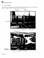
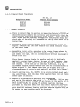
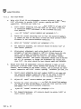
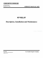
RELAY INSERTION
The KP relay is inserted into the plug connector and secured with two hinged lock
plates. Figure 1 shows a typical KP relay installation.
RH
CONNECTOR
LH
CONNECTOR
LOCK PLATE
PIN GUIDE
KP STYLE RELAY
MOUNTING
BAR SUPPORT
Figure 1.
3623 P• 8
KP Relay Installation
RELAY GUIDE
UNION SWITCH & SIGNAL
El3
SECTION III
FIELD MAINTENANCE
3.1
INTRODUCTION
The necessary periodic preventive maintenance procedures which must be performed
to ensure continuous, proper, and efficient operation of the KP relays covered in
this manual are provided in this section. Field maintenance covers periodic
inspections and performance tests.
3.2
SERVICE REQUIREMENTS
If service (field) values are given in service instructions covering the
equipment or system in which the KP relays are used, those recommendations should
be followed. In the absence of such values, it is suggested that relays having a
pick-up greater than 110% of the value shown in the tables of this service
manual, or a drop-away less than 67% of the tabulated value, be taken out of
service for recalibration.
3.3
CLEANING
For general cleaning, a small, dry fine-bristled (camel's hair) brush may be
used. Contacts and stop pin surfaces may be cleaned by brushing lighly with a
clean fine-bristled brush moistened with clean denatured ethyl alcohol and then
drying immediately with a strip of clean lintless cotton tape.
3.4
PERIODIC PERFORMANCE TEST
3.4.1
General
These relays are normally used in circuits provided with spark protective
features; accordingly, contacts should require little special attention.
Periodic performance checks should include:
a.
A check of calibration values at regular intervals.
b.
Observation of the general condition of relay operating parts visible
through the cover glass to make certain that the spark protective
features are functioning.
The sensitive biased relays, such as are used in code line circuits, should have
more frequent calibration checks than the less sensitive stick type relays.
Recommended rate is once or twice a year initially, with subsequent checks gauged
by results of previous records.
3623 p. 9
ffi
UNION SWITCH 8c SIGNAL
3.4.2
Test Procedures
Test the operating characteristics of the KP relays as follows.
3.4.2.1
Recommended Test Equipment
NOMENCLATURE
PART/MODEL/TYPE NO.
Power Supply,, 0-40 Vdc
Digital Multimeter (two required)
DPDT (Double pole, double throw)
Switch
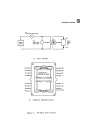
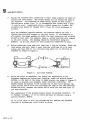
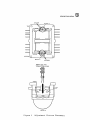
3.4.2.2 KP Biased Relay Test Procedure.
2, and proceed as follows:
HP6205B or equivalent
HP3435A or equivalent
Connect the circuit as shown in figure
a.
Set Ml to appropriate current range.
b.
Set M2 to appropriate voltage range.
c.
Set DC power supply to appropriate output range.
d.
Set switch Sl to Normal.
e.
Turn DC power supply on.
f.
Observe Ml (Current Monitor) and adjust DC power supply output control
to charge the relay (Charge equals four times pick up or working), see
table II or III.
g.
Gradually reduce current until front contacts open.
dropaway value.
h.
Further decrease current, if necessary, until pins touch pole pieces.
This is the full dropaway value.
i,
Momentarily open circuit, then close it and gradually increase current
until relay closes its front contacts, This is the pick up value.
j.
Further increase current, if necessary, until the armature stop pins
touch the pole pieces. This is the working value.
k.
Test concluded. Disconnect test circuit, and return relay to its
original location.
3623 P• 10
This is the
UNION SWITCH & SIGNAL
M1
(CURRENT MONITOR)
A
+1 (+2)
+
M2
POWER
SUPPLY
(VOLTAGE
MONITOR)
V
RELAY
UNDER
TEST
NORMAL
-1 (-21
A.
Test Circuit
0
0
2R
1N
1R
2N
LOOKING AT
FRONT OF UNIT
1P
+1
2P
-1
(
)
+2
-2
4P
3P
4N
3R
4R
3N
0
B.
0
Terminal Identification
Figure 2.
KP Relay Test Circuit
EB
ffi
UNION SWITCH & SIGNAL
3.4.2.3 KP Stick Relay.
proceed as follows:
Connect relay test circuit as shown in figure 2, and
o.c.
a.
Set Ml to read in the appropriate
b.
Set M2 to read in the appropriate D.C. voltage range.
Ce
Set the
d.
Set switch Sl to Reverse.
e.
Turn the D.C. power supply on.
f.
Observe Ml, Current Monitor, and adjust DC power supply output
control to charge the relay (Charge equals four times pick up or
working), see table I. Relay should energize in the reverse position.
g.
Adjust DC power supply output control to gradually decrease current
reading on Ml to zero. Reverse contacts should remain closed.
h.
Set switch Sl to Normal.
1.
Adjust DC power supply output control to gradually increase current
until relay armature picks up and normal contacts close. Current
monitor Ml and voltage monitor M2 should indicate the minimum pickup
and working values indicated in table I.
j.
Adjust DC power supply output control to decrease current reading on
Ml to zero. Normal contacts should remain closed.
k.
Set switch Sl to Normal.
1.
Adjust DC power supply output control to charge relay (see table I).
m.
Gradually reduce current to zero. Then reverse polarity and
gradually increase current to determine pick up value.
n.
The minimum pickup and working values obtained in steps i and m,
above, should be as nearly alike as possible.
o.
Test concluded. Disconnect test circuit, and return relay to its
original location.
n.c.
ma range.
power supply to the appropriate output range.
UNION SWITCH & SIGNAL
EB
SECTION IV
SHOP MAINTENANCE
4.1
INTRODUCTION
This section provides the information necessary to perform shop level repairs of
the KP relays covered in this manual. In general, relays arriving at the shop
for repair have been checked at the field and have been found to perform
unacceptably.
4.2
CLEANING
Before recalibration, all foreign matter should be removed from the interior of
the relay, particular attention being paid to the contacts and armature stop
pins. Follow up with procedure given in paragraph 3.3.
4.3
INSPECTION
Inspect the relay for signs of physical damage, such as cracked or broken cover,
cracked or damaged housing, and damaged and/or missing contact block terminals
and indexing pins. If severe damage is found, a careful inspection of the
interior components should be made for obvious physical damage.
4.4
TEST EQUIPMENT
The following test equipment is required to perform the tests presented in this
section.
Tool to Tool Armature - N243000
Tool to Tool Armature - N243001
Tool to Tool Armature - N243002
Tool to Tool Armature - N347547
Adjusting Tool - N242994
Contact Adjusting Tool - N243059
Spring Gauge - N320728
Inspection Fixture Tool - T35154
Inspection Fixture Tool - T35202
4.5
4.5.1
TESTS AND CHECKS
Fixed Contact Elements
Unless major repairs are necessary, the original calibration values of style KP
relays may be obtained by slight adjustment of the fixed contact elements.
Contact adjustment tool, M243059 has been specially designed for this purpose.
All bending of contact elements should be restricted to the heavier semi-rigid
member. The straight flexible contact springs must not be bent.
3623 P• 13
EB
UNION SWITCH & SIGNAL
All adjustments should be made in such manner as to leave the minimum amount of
tension or fiber stress in the fixed contact members, by slightly overstressing
in the direction of the adjustment and counter-stressing to the final adjustment
position. This method minimizes any tendency toward further change in service.
Special armature positioning tools, references for which are given in the
calibration tables, are inserted in the magnetic gaps to lock the amature in the
correct positions for checking or adjusting the contacts. Leaf gauges should not
be used for this purpose.
Two armature positioning tools, one for each end of the armature, should be
inserted through the magnetic gaps into the coil spools and pressed firmly in
position until all armature motion is taken up. When off-center positions are
being checked, care should be taken that the top and bottom tools are so inserted
as to provide the same direction of off-center locking in order to prevent damage
to the pivots.
The armature positions at which the contacts should just make or break should be
the basis for all contact adjustments.
With the armature locked in position, contacts should be adjusted to the point of
making; i.e., between a barely visible gap, to the point of just making contact.
4.5.2
Midstroke Adjustment
Relays having the midstroke adjustment can have all contacts checked with one
setting of the tools.
4.5.3
Off-Center Adjustment
When off-center adjustments are involved, one setting of the tools will serve for
checking the normal contacts, after which the same tools can be used for checking
the reverse contacts by reversing the prongs of the tools in the magnetic gaps to
lock the armature on the other side of center position.
4.6
REPAIRS AND REPLACEMENT
4.6.l
Dissassembly
Dismantle the relay only to the degree necessary to complete repair. Refer to
the parts list for part information and location of parts. In general, to
dismantle the KP relay, proceed with the following sequence:
a.
Remove relay cover
b.
Remove/disassemble relay components as required
c.
Remove contacts as necessary.
3623 P• 14
UNION SWITCH & SIGNAL
4.6.2
~
Reassembly
Reassembly is accomplished generally in the reverse order of disassembly. The
following paragraphs provide additional instructions to be followed during
reassembly of this relay. Do not overtighten or force parts when reassembling a
relay. Upon completion of reassembly, calibrate the relay as directed in
paragraph 4.8.
4.6.3
Rotor
If the roter has been damaged, or requires restoration other than by minor
bending of springs, it should be replaced. Ordering references for complete
rotor assemblies are given in this section for each type of relay.
Before it is assembled to the relay, each complete rotor assembly should be
inserted in inspection fixture tool No. T-35154 and the adjustment of the contact
springs and flexible connectors checked and, if necessary, adjusted. If any
change of more than 0.005 inch is necessary, the rotor should be adjusted and
baked at 2400 F for six hours, or at 2000F for fifteen hours and then
rechecked after baking.
4.6.3.1
Stick Type Relays
All relays with 4N-4R contacts use rotor Nl91461. All relays with 2N-2R contacts
except N341621 and N381621 use rotor Nl91382. Relay N341621 and N381212 use
rotor N341619.
4.6.3.2
Standard Biased Type Relays
Relay Piece Number
Nl91481
Nl91494
N215618
N215619
N215620
N225785
N226848
N236321
*N236656
N240096
N294846
N296500
N298221
N298263
N305256
N312193
Part No. of
Complete Rotor Assembly
Nl91462
Nl91462
Nl91462
N215621
N215621
Nl91462
Nl91462
N236320
N236320
Nl91462
Nl91462
Nl91462
N236320
N236320
Nl91462
Nl91462
*This relay is no longer available.
3623 p. 15
m
UNION SWITCH & SIGNAL
4.6.3.3
Special Biased Type Relays
Relay Piece Number
N218749
N228492
N302263
4.6.4
Part No. of
Complete Rotor Assembly
Nl91489
N228493
N302536
Assembly Procedure
a.
Place the contact frame in position on inspection fixture No. T35202 and
adjust the contact members both vertically and horizontally so that the
contact buttons just touch the spacer in the fixture. Contact adjusting
tool, N243059 has been specially designed for this purpose. Stamp the
piece number of the relay to be assembled on the top rear surface of the
contact frame.
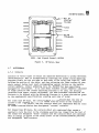
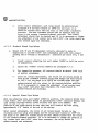
b.
Assemble the front trunnion bracket to the contact frame as shown in
figure 3. Observe that the screw heads do not extend beyond the front
of the contact frame.
c.
Assemble the rotor, coils, and yokes to the contact frame as shown in
figure 3 without fastening the yokes tightly. If the fit between coils
and yokes is too tight, the coil notches should be filed just enough to
avoid a force fit.
Place the rear trunnion bracket in position and with it held firmly
against the contact frame, observe, by means of a dial indicator, that
the rotor has from 0.005 inch to 0.010 inch end play between the front
and trunnions. If the end play is less than 0.005 inch, it may be
increased by applying spacer washers under the rear trunnion bracket as
shown in figure 3. Also observe that there is at least 0.015 inch
clearance between the rotor hub and each coil as called for in figure 3.
d.
Insert adjusting tools, No. N242994 in the slots provided at each end of
the contact frame. Hold the yokes firmly against these tools and fasten
yokes tightly in position.
e.
Remove the adjusting tools and place fully charged magnets in position
and see that the armature takes either extreme position. With the rotor
held in position against one pair of pole faces, fix the position of the
rear trunnion bracket by pouring 7% anitmony lead into the holes
provided. All stop pins should now touch their respective poles faces
when the armature is in either extreme position. If any stop pin is
more than 0.002 inch away from its pole face when the opposite stop pin
is seated, the rear trunnion should be relocated.
3623 P• 16
UNION SWITCH & SIGNAL
REAR
GASKET
PERMANENT
MAGNET
GLASS
FILL WITH 7% ANTIMONY LEAD
SPACER WASHERS
( AS REQUIRED)
FRONT
COVER
SECURE COIL USING
REO GLYPTAL ENAMEL
APPLIED PER FIG. 5
YOKES
F'RAME
TAG
Figure 3.
KP Relay
3623 P• 17
m
UNION SWITCH & SIGNAL
f.
Fasten the flexible heel connectors to their frame supports by means of
eyelets and then solder. The solder should not run beyond the ends of
the supports. All soldering on these relays should be done using a
non-corrosive solder flux. It is recommended that solder with a resin
-5 core be used. Immediately after a solder connection is made, the
soldered area should be cleaned with a clean dry cloth moistened in
alcohol.
With the permanent magnets removed, the armature should now take a
central position with respect to the pole faces. If the armature is
off-center, the brass members to which the heel connectors are attached
should be bent until the armature takes a central position with respect
to the pole pieces. The bending should be distributed among all
members. In no case should the heel connectors themselves be bent.
g.
Before soldering, form each coil lead into a loop as follows: Where the
lead enters the coil, bend it away from the coild end of a 1/8 inch
radius and then form it in a circular loop about 1/4 to 3/8 inch in
diameter as shown in figure 4.
II
1
4
Figure 4.
h.
II
TO
3
8 DIA.
Coil Lead Forming
After the relay is assembled, but before the application of the
permanent magnets and before heat treating, apply red glyptal enamel
A40266, to the back of the relay in eight places, (as shown if figure 5)
in order to prevent coil movement under vibration conditions. The
enamel should be applied on the outside end of both coils between the
yokes and the end of each coil including one edge of the yoke mounting
screws and also, between the inside end of each coil and each side of
the rear trunnion.
The consistency of the glyptal enamel should be watched carefully.
it becomes "stringy", it is too thick and must be thinned, using a
special thinner, A40172.
If it is too thin, it will run through and not perform the intended
function of holding the coils firmly in place.
3623 P• 18
If
UNION SWITCH & SIGNAL
0
O
i.---- RELAY
CONTACT
FRAME
....---+--- YOKE
......-...-+----COIL
~--~--REAR
TRUNNION
0
0
XXXX - Red Glyptal Enamel, A40266
Figure 5.
4.7
4.7.1
KP Relay, Rear
ADJUSTMENTS
Contacts
Contacts of various types of relays are adjusted differently to produce different
characteristics. This is accomplished by inserting the proper contact adjusting
fixtures firmly into the air gaps at both ends of the relay (see figure 6), thus
holding the position of the rotor, and then adjusting the fixed contacts so that
their contact buttons just touch corresponding contact buttons on the flexible
contact members. Contact adjusting tool, No. M243059 has been specifically
designed for this purpose. In no case shall flexible contact members be adjusted
to align contacts. The contact adjusting fixtures to be used, the deviation
permitted from perfect contact adjustment, the heat-treatment required, and the
contacts to be adjusted with the adjusting fixtures in a given position are given
in the supplementary specifications covering each type of relay.
For stick type KP relays, the contacts which are compressed when the rotor is
turned to the clockwise position (as viewed from the front of the relay) are
designated "normal" contact, and the contacts which are compressed when the rotor
is turned counterclockwise asre designated "reverse" contacts.
For biased type KP relays, the contacts which are compressed when energy is
applied to turn the rotor to the clockwise position (as viewed from the front of
the relay) are designated "front" contacts and the contacts which are compressed
when no energy is applied to the relay (rotor in the counterclockwise position)
are designated "back" contacts.
3623 P• 19
m
UNION SWITCH & SIGNAL
4.7.1.1
a.
b.
Stick Type Relays
Relays with 4N and 4R non-independent contacts adjusted to make at
0.025" off-center to provide 0.050" contact opening and 0.030" contact
compression. Calibrate per table I-A.
1.
Insert contact adjusting tool part number 243001 in air gaps with
the stencilled members toward the front of the relay to hold the
rotor position 0.025" off-center in the clockwise direction.
2.
Adjust all "normal" contact members per paragraph 4.7.1.
3.
Reverse the contact adjusting tool so that the stencilled members
are toward the rear of the relay to hold the rotor position 0.025"
off-center in the counterclockwise direction.
4.
Adjust all "reverse" contacts per paragraph 4.7.1.
5.
For inspection purposes, all contacts should be within 0.002" of
their correct position.
6.
After contact adjustment, each relay should be calibrated per
paragraph 4.8 and heat-treated at 2400 for fifteen hours with the
rotor in the normal (clockwise) position. The heat treatment
should then be repeated with the rotor in the reverse (counterclockwise) position. The contact adjustment should then be checked
and if it is necessary to change the adjustment any contact more
than 0.002", the relay should be heat treated again and rechecked.
Relays with 2N and 2R independent contacts adjusted to make at 0.005"
off-center to provide 0.010" travel between the opening of the reverse
contact, and the making of the normal contact, and to provide for 0.030"
contact compression and 0.040" contact opening. Calibrate per table I-B.
1.
Insert contact adjusting tool part number 243002 in air gaps with
the stencilled members toward the front of the relay to hold the
rotor position 0.005" off-center in the clockwise direction.
2.
Adjust all "normal" contact members per paragraph 4.6.4 a.
3.
Reverse the contact adjusting tool so that the stencilled members
are toward the rear of the relay to hold the rotor position 0.005"
off-center in the counterclockwise direction.
4.
Adjust all "reverse" contacts per paragraph 4.7.1.
5.
For inspection purposes, all contacts should be within 0.002" of
their correct position.
3623 P• 20
UNION SWITCH & SIGNAL
TOP
Q
0
(
BOTTOM
J
Q
0
AIR GAPS
INSERT TOOL INTO
TOP & BOTTOM Al A GAP
DETAIL A
Figure 6.
Adjustment Fixture Placement
ffi
ffi
UNION SWITCH & SIGNAL
6.
4.7.1.2
a.
4.7.1.3
After contact adjustment, each relay should be calibrated per
paragraph 4.8 and heat-treated at 240°F for six hours or at
200°F for fifteen hours with the rotor in the normal (clockwise)
position. The heat treatment should then be repeated with the
rotor in the reverse (counterclockwise) position. The contact
adjustment should then be checked and, if it is necessary to change
the adjustment of any contact more than 0.002", the relay should be
heat treated again and rechecked.
Standard Biased Type Relays
Relays with 2F and 2F independent contacts, adjusted to make in
midposition to provide 0.030" inch compression and 0.030 inch contact
opening and no overlap in midposition. Calibrate per table II-A, C and
D.
1.
Insert contact adjusting tool part number 243000 to hold the rotor
in midposition.
2.
Adjust all "normal" contact members per paragraph 4.7.1.
3.
For inspection purposes, all contacts should be within 0.001 inch
of perfect adjustment.
4.
After all contact adjustments, the rotors of all relays should be
held in the clockwise position using wood wedges and heat-treated
at 240° F for six hours or at 2QOOF for fifteen house and then
reheat-treated with the rotors in the counterclockwise position.
If it is necessary to change the adjustment of any contact more
than 0.002" inch after heat treatment, the relay should be
reheat-treated and rechecked.
Special Biased Type Relays
With the adjusting tools part number 243003 in position, the contacts should just
touch within .001" and there should be approximately 0.005" clearance between the
load springs (springs wihout silver buttons) and their stop members. The
position of the stops should be such that they will contact the load spring
approsimately 1/8" inside of the end of the spring.
After contact adjustment, the rotors of all relays should be held in the
clockwise position using wood wedges and the relays heat-treated at 2400F for
six hours or at 200°F for fifteen house and then reheat-treated with the rotors
in the counterclockwise position. If it is necessary to change the position of
any contact more than 0.002" after heat treatment, the relay should be
reheat-treated and rechecked.
UNION SWITCH & SIGNAL
4.8
EB
CALIBRATION
4.8.1
4.8.2
Permanent Magnet Calibration and Adjustment
a.
Permanent magnets should be assembled on the relay with the poles marked
"N" to the right as viewed form the front of the relay. The poles
marked "N" should attract the end of a magnetic compass which points
toward geographic South.
b.
Relay calibration is finally determined by adjusting the strength of the
permanent magnets. A pair of magnets should be placed over the coils of
a relay to check if they seat squarely against the yokes. They should
then be charged to full saturation, and each magent partially
demangetized by applying a convenient value of alternating flux to the
magnets. If a magnet is discharged too far, it should again be charged
to full saturation and discharged with a slightly lower value of
alternating flux.
c.
The magnets should be assembled on the relay with the like poles in the
same direction so that, with the relay in the normal operating position
and with positive energy applied to the left of either coil, the
armature will rotate to the clockwise position as viewed from the front
of the relay.
d.
In checking calibration, the energizing circuit should be opened for one
second before reading the pick-up value; and the relay should be
energized to four times maximum pick-up beofre reading the drop-away
value.
Stick Type Relays
The relay pick-up (reversal) calibration should be checked in both directions
(clockwise and counterclockwise) using each coil separately. The pick-up values
must fall within the limits specified in table r. If either or both are too
high, the magnets should be further demagnetized with a slightly higher value of
alternating flux. If either or both are too low, the magnets must be agian fully
charged and d~I\\agnetized with a slightly lower value of alternating flux.
For those relays which require a higher pick-up in one direction than the other,
the fixed contact members may be adjusted slightly.
4.8.3
Standard Biased Type Relays
Three points are taken on pick-up as follows: Start, Pick-up (close front
contacts), and Working (Full Stroke). Two points are taken on drop-away as
follows: Drop-away (open front contacts), and Full Drop-away. !he pick-up and
drop-away calibration values should be checked for both front contacts and must
fall within the limits specified in table II. If the start value on pick-up is
too high, the magnets should be further demagnetized with a higher value of
alternating flux. If the start value on pick-up is too low, the magnets should
again be fully charged and demagnetized with a smaller value of alternating flux.
3623 P• 23
m
UNION SWITCH & SIGNAL
4.8.4
Special Biased Type Relays
The pick-up drop-away values must be within the limits shown in table III. On
pick-up, the amount of current required to close the front contact (pick-up
value) must also complete the stroke (working value). Likewise, on drop-away,
the amount of current required to open the front contact (drop-away value) must
also complete the stroke (full drop-away value). In case this action cannot be
obtained, the stops for the load springs may be adjusted to contact the load
springs nearer the free end. In no case should they be closer than 1/32" to the
free end of the load springs.
4.8.5
Calibration Tables
KP relays calibration should be checked by the usual calibration equipment. The
calibration values should be taken on each coil separately in accordance with the
accompanying tabulations.
For normal polarity, apply positive battery to the left-hand terminal of either
coil. This will rotate the armature of any KP type relay clockwise. For reverse
polarity, apply negative battery to the left-hand terminals. This will rotate
the armature counterclockwise.
The stick relay should first be charged at reverse polarity to approximately four
times maximum pick-up value and the current then gradually reduced to zero.
Reverse the polarity, then gradually increase the current until the armature
moves to the clockwise position to determine the normal pick-up value. The
armature should go to full stroke at this same value and should remain at full
stroke when the relay is deenergized. The relay should then be charged at normal
polarity by increasing the current to approximately four times maximum pick-up
value. Then the current should be gradually reduced to zero. Reverse the
polarity and gradually increase the current until the armature moves to the
countercloskwise position to determine the reverse pick-up value. The armature
should go to full stroke at this same value and should remain at full stroke when
the relay is deenergized.
The biased relay should first be charged at normal polarity to approximately four
times maximum pick-up value, and the current then gradually reduced until the
front contacts open to determine the drop-away value. Further decrease the
current, if necessary, until the armature stop pins touch the pole pieces to
determine the full drop-away value. Open the circuit momentarily, and then close
it and gradually increase the current until the relay closes its front contacts
to determine the pick-up value. Further increase the current, if necessary,
until the armature stop pins touch the pole pieces to determine the working value.
Biased relays return to the counterclockwise position when energy is removed and
will not pick-up when reverse energy is applied.
3623 P• 24
UNION SWITCH & SIGNAL
Table I.
Calibration Values for Stick Type KP Relay Values
A. 4N-4R Non-Independent Contacts - Approximately 0.050" Opening.
Adjust per paragraph 4.7.1.1.a.
Coil Resistance - Ohms
Pick-Up (One Coil)
Mil liamper s
Upper
Max.
Min.
82
82
39
39
82
39
39
12.3
12.3
7.2
22
10.5
10.5
68
68
31
31
68
31
31
9.8
9.8
5.7
16
7.5
7.5
Pc. No.
Code No.
Nl91362
N294847
45690
12368
20
20
Nl91493
45680
105
N217122
N231072
12347
12356
105
105
Nl91500
N314119
N335380
N341621*
N381212*
45780
12370
12380
12456
1070
3800
400
1070
1070
Lower
20
105
-----
20
105
1070
1070
3800
400
1070
1070
B. 2N-2R Independent Contacts - Appr ox ima t ely 0.040" Opening.
Adjust per paragraph 4.7.1.1.b.
N225 784
Nl91499
N262433
N292335
N220821
N337612**
12345
45789
12360
56890
56780
12390
12.5
20
105
400
1070
400
12.5
28
105
400
1070
400
36
28
13. 3
7.3
4.6
7.3
29
22
10.8
5.9
3.4
5.9
* Two normal and two reverse contacts removed.
** Magnets and polarity reversed.
B.
Specia 1 Relay (Off-Center Adj.) 2N-2R Independent Contacts
Approximately 0.040" opening. See paragraph 4.8.2
Adjust Per Paragraph 4.7.1.1.b.
Pick-Up (One Coil) Milliamperes
Code
Pc. No.
No.
N231412
12357
(Rev. 5/85)
Counterclockwise
Upper
Lower
Max.
Min.
Max.
Min.
33
12.1
18.l
9.9
13. 9
19.2
28.2
15.9
22.5
73
I
Clockwise
Coil Resistance - Ohms
3623, p. 25
m
UNION SWITCH & SIGNAL
Table II
Calibration Values for Standard Biased Type KP Relays
Adjust Per Paragraph 4.7.1.2
Drop-Away
Milliamperes
Pick-Up Milliamperes
Closed Front
Contacts
Start
Part
No.
Code
No.
N226848
45670
Upper
Lower
N312193
12379
N225785
Coil
Res.
Ohms
Full
Wkg.
Drop-Away
Min.
Max.
Min.
Max.
Min.
Max.
0.86
0.86
164
164
125
125
164
164
125
125
195
195
60
60
Upper
Lower
3.2
3.2
90
90
67
67
90
90
67
67
107
107
32
32
23456
Upper
Lower
12.5
12.5
46.0
46.0
34
34
46
46
34
34
51
51
16.0
16.0
Nl91494
56789
Upper
Lower
20
20
34
34
26
26
34
34
26
26
42
42
12.5
12.5
N294846
12367
Upper
Lower
20
3800
34
2.9
26
2.2
34
2.9
26
2.2
42
3.5
12.5
1.1
N215618
12348
Upper
Lower
105
105
16.0
16.0
11.s
11.5
16.0
16.0
11.s
11.s
19
19
s.8
5.8
N296500
12369
Upper
Lower
105
1070
16.0
5.1
11.5
3.9
16.0
s.1
11.s
3.9
19
6.1
5.8
2
N321408
N380716
12389
Upper
Lower
105
3800
16.0
2.9
11.s
2.2
16.0
2.9
11.5
2.2
19
3.5
5.8
1.1
Nl91481
N374213
57890
Upper
Lower
1070
1070
s.1
5.1
3.9
3.9
5.1
5.1
3.9
3.9
6.1
6.1
2
2
12340
Upper
Lower
3800
3800
2.9
2.9
2.2
2.2
2.9
2.9
2.2
2.2
3.5
3.5
1.1
N240096
N381593
-----
3623 P• 26
1.1
m
UNION SWITCH & SIGNAL
Table II (Continued)
Special Sensitive Relays - 2F-2B Independent Contacts
Approx. 0.30 Inch Opening
Adjust Per Paragraph 4.7.1.2
Pick-Up Milliamperes
Closed Front
Contacts
Start
Code
No.
Part
No.
Coil
Res.
Ohms
Max.
Drop-Away Milliamperes
Min.
Max.
Open Front
Contacts
Min.
Wkg.
Max.
Max.
Min.
Full
DropAway
Min.
N215619
12349
Upper
Lower
105
105
11
11
6.8
6.8
11
11
6.8
6.8
14.2
14.2
4.6
4.6
3.4
3.4
1.9
1.9
N215620
12346
Upper
Lower
105
3.2
11
61
6.8
38
11
61
6.8
38
14.2
80
4.6
26
3.4
19
1.9
10.8
Special Single Contact Button - 2F-2B Independent Contacts
Approx. 0.030 Inch Opening
Adjust Per Paragraph 4.7.1.2
Pick-Up Milliamperes
Start
Code
No.
Part
No.
Drop-Away Milliamperes
Closed Front
Contacts
Open Front
Contacts
Coil
Res.
Ohms
Max.
Min.
Max.
Min.
Wkg.
Max.
Max.
Min.
Full
DropAway
Min.
N236321
12358
Upper
Lower
105
105
9.2
9.2
6.8
6.8
9.2
9.2
6.8
6.8
14.2
14.2
4.6
4.6
3.4
3.4
1.9
1.9
**N236656
12359
Upper
Lower
1070
1070
2.6
2.6
1.9
1.9
2.6
2.6
1.9
1.9
4.1
4.1
1.3
1.3
1.0
1.0
0.5
0.5
*N298221
N298263
-----
Coils in
Multiple
535
3.5v
3.0V
3.5V
3.0V
4.2V
N318066
-----
1070
1070
2.9V
2.9v
2.ov
2.ov
2.9V
2.9v
2.ov
2.ov
4.lV
4.lv
--- 1.3V
--- 1.ov
Upper
Lower
---
1.ov
1.ov
0.5v
0.5V
*
Two relay units Pc.# N298221 are bolted front to front to form one dual
relay Pc. IIN298263. The tabluated calibration values in volts are used
for each half with the coils connected in multiple.
**
This relay no longer available.
3623 P• 27
E:13
UNION SWITCH 8t SIGNAL
Table III
Calibration Values for Special Biased Type KP Relays One Front Contact Only
Pick-Up & Working
Milliamperes
Part
Number
Code
Number
N218749
N228492
N302263
3623 p. 28
Drop-Away
& Full
Drop-Away
Milliamperes
Res.
Coil
Ohms
Max.
Min.
Max.
Min.
12340
Upper
Lower
105
105
30.5
30.5
24.5
24.5
15.5
15.5
11.0
11.0
67890
Upper
Lower
1070
1070
3.1
3.1
1.9
Upper
Lower
3800
3800
2.1
2.1
12378
1.9
0.5
o.s
0.2
0.2
UNION SWITCH & SIGNAL
4.9
m
OPERATIONAL TEST
4.9.1
General Inspection
a.
A general inspection of the contacts shall be made after adjustment to
see that they are properly aligned and meet squarely. The relay
calibration should then be checked. Slight adjustment of the fixed
contact members should be sufficient to meet the calibration.
b.
It should be noted that all lock washers are used where required, and
that they are fully compressed.
c.
The coil leads should be arranged so that they cannot vibrate into such
a position as to interfere with operation of the contacts.
d.
Flexible connectors should be examined to see that they are formed to
provide adequate clearances and are properly soldered.
e.
The tag should be marked with the code no. and serial no. of the relay,
together with data and inspector's initials. This tag should be
inserted in the bottom of the relay as shown in figure 4.
f.
A careful inspection should be made to be sure that all dirt and foreign
matter has been removed form the mechanism, paying special attention to
air gaps and contact surfaces.
4.9.2
Final Inspection
a.
The front cover and back should be carefully assembled so that all
gaskets lie smoothly and are compressed, sealing the relay tightly.
Observe that the gasket does not extend beyond the edges of the relay.
b.
After sealing, the relay should be examined through the cover to see
that contacts, flexible connectors, and coil leads have not been
misplaced since calibration.
c.
A final check of relay calibration should be made.
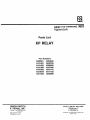
SERVICE MANUAL 3623
Appendix A
Parts List
KP RELAY
Part Numbers
N220821 N294846
N191481 N225785
N191493 N296500
N191499 N347480
N191500 N231412
N215618 N217122
N371940 N240096
UNION SWITCH
& SIGNAL INC.
A member of the!ANSALDO!Group
5800 CORPORATE DRIVE
PITTSBURGH, PA 15237
January, 1982 (Rev. May,1985)
ID0044F/OxxxF
C-7/89-25-861-3
COPYRIGHT 1989, UNION SWITCH & SIGNAL INC.
PRINTED IN USA
UNION SWITCH & SIGNAL
m
Parts List For KP Relay
Reference
A
B
c
D
E
F
G
H
J
K
L
M
N
p
Relay Part
Number
No.
Contacts
Coil Ohms
Nl91481
Nl91493
Nl91499
Nl91500
N215618
N217122
2N
4N
2N
4N
2N
4N
2B,
4R,
2R,
4R,
& 2B,
& 4B,
N220821
N225785
N231412
N240096
N294846
N296500
N347480
N371940
2N
2N
2N
2N
2N
2N
4N
4N
& 2R, I*
& 2B, I*
&
&
&
&
& 2R,
& 2B,
& 2B,
& 2B,
& 4R,
& 4R,
I*
N**
I*
N**
I*
N**
I*
I*
I*
I*
N*
N**
Upper
Lower
1070
105
20
1070
105
105
1070
20
20
1070
105
105
1070
12.s
75
3800
20
105
20
12.s
1070
12.5
33
3800
3800
1070
20
12.s
*I= Independent Contacts
**N = Non-Independent Contacts
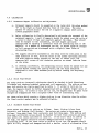
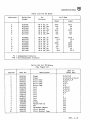
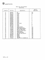
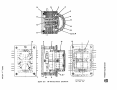
Parts List for KP Relays
(See Figure Al)
Item No.
Part No.
1
1
2
2
2
2
N191363
Nl91480
Nl91462
Nl91461
Nl91382
N347479
N220783
Nl91479
N226572
Nl91498
N321410
N231411
N248743
Nl91385
N286398
J047662
Ml51836
Ml91464
M241325
Nl91429
3
3
3
3
3
3
3
4
5
6
7
8
9
10
Description
Frame
Frame
Rotor Comp
Rotor Comp
Rotor Comp
Rotor Comp
Coil
Coil
Coil
Coil
Coil
Coil
Coil
Yoke
Screw
Washer-6PS LK
Nut
Permanent Magnet
Pivot Bracket
Pivot Bracket Comp
Used on
Relay Ref.
B,D,F,N,P
A,C,E,G,H,J,K,L,M
A,E,H,K,L,M
B,D,F
C,G,J
N,P
A,D,G,M
B,E,F,M
B,C,L,N
H,P
J
J
K,L
ALL
ALL
ALL
ALL
ALL
ALL
ALL
3623, P• Al
m
UNION SWITCH & SIGNAL
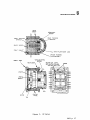
Parts List for KP Relays
(Continued)
Item No.
11
12
13
13
13
13
13
13
13
13
13
13
13
13
13
13
14
15
16
17
18
19
20
21
22
23
24
25
26
3623, P• A2
Part No.
Description
M242271
M273771
M248353
M248362
M248364
M248365
M248354
M248357
M248358
M248361
M248368
M248371
M294844
M296501
M347549
M371941
J047081
J776373
J047355
J480006
J522142
J070883
J062742
J075599
M233946
M233947
M317304
M279717
J525024
Nut
Screws
Cover
Cover
Cover
Cover
Cover
Cover
Cover
Cover
Cover
Cover
Cover Back
Cover
Cover
Cover
Gasket-Rubber
Cover-Front Clear
Gasket-Molded Rubber
Nut-4-40 Hex Steel
Screw-4-40 Hex Steel
Eyelet-Brass
Plate-Alum Name
Tag with Opq Acetate
Washer
Washer
Washer
Springs
Screw-4-40 X 3/16RDH Par
Used on
Relay Ref.
ALL
ALL
A
B
c
D
E
F
G
H
J
K
L
M
N
p
ALL
ALL
ALL
ALL
ALL
ALL
ALL
ALL
ALL
ALL
ALL
ALL
ALL
9
8
12
10
20
14
~-
+ _,,
:.&'
r-t--· ,r},
• _,:.,_ .. I
'
F •· ."l ..,.1_"'"
I
-¥.-rt-
1
2
19
@~==-- -,:-::~~-:=--~
~22,23,24
-G
18
~~
-
c,:l-'7F .1
,~~:-: . ..=.
,--r,~. I
~ • «',t r:""'·_-,:
t'-~7
' .c-- .. ,.
-,,'1--,-
I
r~· _·,-+-"'-=:::-,-=~
j
I ~..o;;, _-- f ,. '......
( '
: ,:". \
w
...w
't,
>
w
t
(
-r-~'----;
,:-a!'! ~'
I
I
, .'
<3'
N
•< / '
- - -~ -r
~ - fl - -, .... !
L
'{\-~
-
f
·~ JI ~,·
-43- --- ~
t
~,
..
t--~--!,·/"r:vr,
"-.-~
I
~--,,~~...,
c
z
0
- -' .\
~"1
~
,--r:.l
z
..~
I
..~
~,-i::~:!.-'
::c
'"~~-, ---
--~., ......... "'-.I
t- -
fl)
i5
z
'17
21
Figure Al.
>
,-
3
KP Relay Parts Location
~
:.Li 6
L:::!.l ?
~
EB