1
UNION SWITCH & SIGNAL
0
O
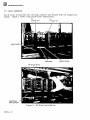
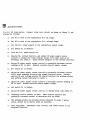
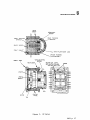
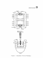
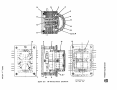
i.---- RELAY
CONTACT
FRAME
....---+--- YOKE
......-...-+----COIL
~--~--REAR
TRUNNION
0
0
XXXX - Red Glyptal Enamel, A40266
Figure 5.
4.7
4.7.1
KP Relay, Rear
ADJUSTMENTS
Contacts
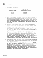
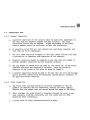
Contacts of various types of relays are adjusted differently to produce different
characteristics. This is accomplished by inserting the proper contact adjusting
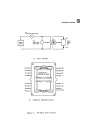
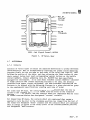
fixtures firmly into the air gaps at both ends of the relay (see figure 6), thus
holding the position of the rotor, and then adjusting the fixed contacts so that
their contact buttons just touch corresponding contact buttons on the flexible
contact members. Contact adjusting tool, No. M243059 has been specifically
designed for this purpose. In no case shall flexible contact members be adjusted
to align contacts. The contact adjusting fixtures to be used, the deviation
permitted from perfect contact adjustment, the heat-treatment required, and the
contacts to be adjusted with the adjusting fixtures in a given position are given
in the supplementary specifications covering each type of relay.
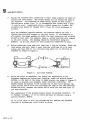
For stick type KP relays, the contacts which are compressed when the rotor is
turned to the clockwise position (as viewed from the front of the relay) are
designated "normal" contact, and the contacts which are compressed when the rotor
is turned counterclockwise asre designated "reverse" contacts.
For biased type KP relays, the contacts which are compressed when energy is
applied to turn the rotor to the clockwise position (as viewed from the front of
the relay) are designated "front" contacts and the contacts which are compressed
when no energy is applied to the relay (rotor in the counterclockwise position)
are designated "back" contacts.
3623 P• 19