1
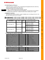
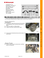
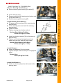
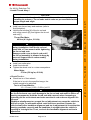
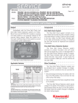
SERVICE
INFORMATION
Category
Factory Directed Modification
Model
KVF750-A1/B1
Serial No.
Date
DC8971A/2A
Dec. 13, 2005
Subject
Tie-rod End Ball Separation (RECALL)
REVISED
Discard the previous one
Dated Dec.8, 2005
Subject
Tie rod separation caused by either wear or
impact can occur during operation. This can
disconnect the front wheel from the steering
control, and could result in an accident with
risk of injury or death to the ATV operator.
Tie-rod assy
Eligibility
Units within the V.I.N. ranges listed below are eligible for repair.
Eligible units
Model
KVF750-A1
V.I.N.
JKAVFDA1√5BXXXXXX
JKAVF750AABXXXXXX
KVF750-B1
JKAVFDB1√5BXXXXXX
Market
All other than
Europe
Europe
All other than
Europe
Serial Number Range
500001 thru 518688
600008 thru 600969
500001 thru 506051
√: Check digit, XXXXXX: Serial Number
Kawasaki Action
Kawasaki has initiated a Factory Directed Modification (RECALL) campaign to repair all
eligible units according to the “Required Action in Field” section of this Service Information.
Distributor and Dealer Action
Repair all eligible units, including sold units in field and unsold units in Dealer. Also,
repair all Tie-rod Ends and Tie-rod sold as spare parts in fields and unsold parts in Dealer
and Distributor.
Page 1 of 6
Quality Division, Consumer Products & Machinery Company, Kawasaki Heavy Industries, Ltd.
F
F
A
A
C
C
T
T
O
O
R
R
Y
Y
D
D
II
R
R
E
E
C
C
T
T
E
E
D
D
M
M
O
O
D
D
II
F
F
II
C
C
A
A
T
T
II
O
O
N
N
(1) Notify Registered Owners:
Notify all owners of eligible units of modifying the designated all terrain vehicle by
means of sending letters or any other else.
Kawasaki strongly recommends customer;
(1)
Do not ride the vehicle until it has been repaired
added
(2) Perform the “Tie-rod End Free Play Inspection”, as instructed on the separate
sheets, prior to each ride, if customer must ride the vehicle prior to repair.
(2) Modify the vehicles:
By following the repair procedure, repair all eligible units, including sold units in the
field and unsold units in your inventory.
Parts Information
The following parts are required for this repair V.I.N. serial number range.
Description
P/N
Qty
Kit, Rod-Assy-Tie
99999-0084
1
Kit, Rod-Assy-Tie
99999-0086
1
Remark
V.I.N. serial number range
KVF750-A1
500001 thru 517987
600008 thru 600860
KVF750-B1
500001 thru 505537
KVF750-A1
517988 thru 518688
600861 thru 600969
KVF750-B1
505538 thru 506051
Kit, Rod-Assy-Tie contents: 99999-0084
Description
P/N
(1) Rod-Assy, Tie
39110-0024
(2) Washer, 10.2×20×1.5
92022-3742
(3) Pin-Cotter, 2.0×15
550D2015
(4) Holder-Damper
13280-0200
(5) Damper
92161-0385
(6) Nut, Lock, 6mm
92015-1603
(7) Bracket, Steering
11054-0589
(8) Bolt, 8×35
92151-3763
(9) Pin-Cotter, 3.0×25
550D3025
(10) Joint-Ball
59266-0016
Qty
2
6
4
1
2
2
1
2
1
1
Kit, Rod-Assy-Tie contents: 99999-0086
Description
P/N
(1) Rod-Assy, Tie
39110-0024
(2) Washer, 10.2×20×1.5
92022-3742
(3) Pin-Cotter, 2.0×15
550D2015
Qty
2
6
4
DC8971A/2A
Page 2 of 6
Remark
TIE-ROD-END
TIE-ROD-END
DAMPER
FIT HOLER
FOR DAMPER
STRG SHAFT
STRG LOWER BJ
STRG LOWER END
STRG LOWER END
Remark
TIE-ROD-END
TIE-ROD-END
F
A
C
T
O
R
Y
D
I
R
E
C
T
E
D
M
O
D
I
F
I
C
A
T
I
O
N
(1) Rod-Assy, Tie
(2) Washer, 10.2×20×1.5
(3) Pin-Cotter, 2.0×15
(4) Holder-Damper
(5) Damper
(6) Nut, Lock, 6mm
(7) Bracket, Steering
(8) Bolt, 8×35
(9) Pin-Cotter, 3.0×25
(10) Joint-Ball
Repair Procedures (in case the vehicle is out of the crate.)
Refer to the appropriate sections of the Service Manual (P/No. 99924-1334-01, -02, -03)
for information and procedures related to parts removal and installation.
(for All Kit, Rod-Assy-Tie)
< Preparation >
If necessary, clean the area around the knuckle
and suspension arm so that the work area is
clean.
Place the vehicle on a flat surface.
Loosen the wheel nuts [A] at both sides.
Lift up the front wheels and remove the wheel nuts
and wheels.
< Remove Tie-rod >
Remove cotter pins, tie-rod end nuts, washers
and tie-rod assy [A].
DC8971A/2A
Page 3 of 6
F
A
C
T
O
R
Y
D
I
R
E
C
T
E
D
M
O
D
I
F
I
C
A
T
I
O
N
(for Kit, Rod-Assy-Tie P/N 99999-0084)
< Remove Steering Stem Bearing >
Remove steering stem bearing joint bolts [A].
Lift the steering stem.
Remove cotter pin [A], steering stem bottom end
nut [B] and collar [C].
Remove steering stem bearing [D].
< Install Steering Stem Bearing >
Fill grease up the seal grooves in new steering
stem bearing.
Lift the steering stem and install the steering
stem bearing.
Install the collar.
Tighten steering stem bottom end nut.
Steering Stem Bottom End Nut:
62 N·m (6.3 kgf·m, 46 ft·lb)
Install new holder (damper) [A] on the steering
stem bearing.
Tighten new steering stem bearing and new
holder with new joint bolts [B] (both sides).
Steering Stem Bearing Joint Bolts:
23 N·m (2.3 kgf·m, 17 ft·lb)
< Install Damper >
Install new dampers [A] to the holder.
Tighten dampers with new damper nuts [B] (both
sides).
Damper Nuts:
8 N·m (0.8 kgf·m, 6 ft·lb)
< Install New Bracket >
Install new bracket [A] on the old bracket of the
steering stem.
DC8971A/2A
Page 4 of 6
F
A
C
T
O
R
Y
D
I
R
E
C
T
E
D
M
O
D
I
F
I
C
A
T
I
O
N
(for All Kit, Rod-Assy-Tie)
< Install Tie-rod Assy >
CAUTION
Do not loosen the tie rod end locknuts on the new tie-rod assy before
installing tie-rod assy. Tie rod ends and tie rods are pre-assembled at the
proper length and angle.
Install new tie-rod assy and washers (refer to
first illustration).
Hold the flat surface [A] of the tie-rod end
with a thin wrench [B], and tighten the tie-rod
end nut[C].
Tie-rod End Nuts:
42 N·m (4.3 kgf·m, 31 ft·lb)
WARNING
Be careful not to damage the rubber seal
during installation. Hold the tie rod end
shaft with a 17mm wrench while tightening
the tie rod end nuts.
Damage could occur to the tie rod end if
the tie rod assembly is allowed to hang by
one end. Support the tie rod assembly
during installation.
Install new cotter pins.
Install front wheels.
Tighten the wheel nuts in a criss-cross pattern.
Wheel Nuts:
57 N·m (5.8 kgf·m, 42 ft·lb)
< Check Toe-in >
Check toe-in of front wheels.
If the toe-in is not in the specified range, the
vehicle needs to be adjusted.
Toe-in of Front Wheels:
-10 ~ 10 mm (-0.39 ~ 0.39 in.) at 1G
WARNING
Allowing the tie rod end body to contact the shaft while loosening or tightening
the tie rod locknuts can cause damage to the tie rod end and result in failure of
steering components. Hold the tie rod end with a wrench when loosening or
tightening the tie rod locknuts and make sure the tie rod ends are aligned 180˚
opposed.
Handlebar misalignment or unequal tie rod adjustment can cause the vehicle to
drift left or right, or mishandle which could lead to an accident. Operate the
vehicle slowly after handlebar alignment and toe-in adjustment to check that the
steering responds correctly and the handlebar is straight when the vehicle is
traveling in a straight line. If not, re-check the handlebar alignment and toe-in
adjustment.
DC8971A/2A
Page 5 of 6
F
A
C
T
O
R
Y
D
I
R
E
C
T
E
D
M
O
D
I
F
I
C
A
T
I
O
N
Repair Verification
Make a small punch mark up the V.I.N. as a
verification mark.
A. V.I.N.
B. Front Axis (left side)
C. Punch Mark
Ⓒ
F
A
C
T
O
R
Y
●
Warranty Information
The labor cost will be reimbursed upon your warranty request.
All other than Europe market
Model
KVF750A1
KVF750B1
Serial Number Range 500001 thru 500001 thru
517987
505537
Flat Rate
1.2 hour
Trouble code
62
Causal Part
Kit, Rod-Assy-Tie
Causal Part No.
99999-0084
Quantity
1
Special Claim ID No.
DC8971A
Claim Type
3
Europe market
Model
Serial Number Range
Flat Rate
Trouble code
Causal Part
Causal Part No.
Quantity
Special Claim ID No.
Claim Type
KVF750A1
600008 thru 600860
1.2 hour
62
Kit, Rod-Assy-Tie
99999-0084
0
DC8971A
3
D
I
R
E
C
T
E
D
KVF750A1
KVF750B1
517988 thru 505538 thru
518688
506051
0.7 hour
62
Kit, Rod-Assy-Tie
99999-0086
1
DC8972A
3
KVF750A1
600861 thru 600969
0.7 hour
62
Kit, Rod-Assy-Tie
99999-0086
0
DC8972A
3
Please issue invoice of total cost incurred for repair in case distributor carries out rework
their inventory before shipping.
■
DC8971A/2A
Page 6 of 6
M
O
D
I
F
I
C
A
T
I
O
N