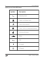
1
Operation and Service Manual
Isolation Amplifier
SIM984
Stanford Research Systems
Revision 1.12 • March 5, 2013
Certification
Stanford Research Systems certifies that this product met its published specifications at the time
of shipment.
Warranty
This Stanford Research Systems product is warranted against defects in materials and workmanship for a period of one (1) year from the date of shipment.
Service
For warranty service or repair, this product must be returned to a Stanford Research Systems
authorized service facility. Contact Stanford Research Systems or an authorized representative
before returning this product for repair.
Information in this document is subject to change without notice.
c Stanford Research Systems, Inc., 2013. All rights reserved.
Copyright Stanford Research Systems, Inc.
1290–D Reamwood Avenue
Sunnyvale, CA 94089 USA
Phone: (408) 744-9040 • Fax: (408) 744-9049
www.thinkSRS.com • e-mail: [email protected]
Printed in U.S.A.
Document number 9-01691-903
SIM984
Isolation Amplifier
Contents
General Information
Symbols . . . . . . . . . . . . . . . . . . . . . . . . . . . . .
Notation . . . . . . . . . . . . . . . . . . . . . . . . . . . . .
Specifications . . . . . . . . . . . . . . . . . . . . . . . . . .
iii
iv
v
vi
1
Getting Started
1.1 Introduction to the Instrument . . . . . . . . . . . .
1.2 Front-Panel Operation . . . . . . . . . . . . . . . . .
1.3 SIM Interface . . . . . . . . . . . . . . . . . . . . . . .
1–1
. 1–2
. 1–2
. 1–4
2
Remote Operation
2.1 Index of Common Commands .
2.2 Alphabetic List of Commands .
2.3 Introduction . . . . . . . . . . .
2.4 Commands . . . . . . . . . . . .
2.5 Status Model . . . . . . . . . . .
2–1
. 2–2
. 2–3
. 2–4
. 2–4
. 2 – 13
3
.
.
.
.
.
.
.
.
.
.
.
.
.
.
.
.
.
.
.
.
.
.
.
.
.
.
.
.
.
.
.
.
.
.
.
.
.
.
.
.
.
.
.
.
.
.
.
.
.
.
.
.
.
.
.
.
.
.
.
.
Circuitry
3–1
3.1 Circuit Descriptions . . . . . . . . . . . . . . . . . . . . 3 – 2
3.2 Schematic Diagrams . . . . . . . . . . . . . . . . . . . 3 – 3
i
ii
Contents
SIM984
Isolation Amplifier
General Information
The SIM984 Isolation Amplifier, part of Stanford Research Systems’
Small Instrumentation Modules family, is a wide bandwidth, low
noise isolation amplifier for use with analog signals from DC to
1 MHz.
Service
Do not install substitute parts or perform any unauthorized modifications to this instrument.
The SIM984 is a single-wide module designed to be used inside the
SIM900 Mainframe. Do not turn on the power until the module is
completely inserted into the mainframe and locked in place.
iii
iv
General Information
Symbols you may Find on SRS Products
Symbol
Description
Alternating current
Caution - risk of electric shock
Frame or chassis terminal
Caution - refer to accompanying documents
Earth (ground) terminal
Battery
Fuse
On (supply)
Off (supply)
SIM984 Isolation Amplifier
General Information
v
Notation
The following notation will be used throughout this manual.
WARNING
A warning means that injury or death is possible if the instructions
are not obeyed.
CAUTION
A caution means that damage to the instrument or other equipment
is possible.
Typesetting conventions used in this manual are:
• Front-panel buttons are set as [Button].
• Front-panel indicators are set as Overload.
• Remote command names are set as *IDN?
• Literal text other than command names is set as OFF.
Remote command examples will all be set in monospaced font. In
these examples, data sent by the host computer to the SIM984 are set
as straight teletype font, while responses received by the host
computer from the SIM984 are set as slanted teletype font.
SIM984
Isolation Amplifier
vi
General Information
Specifications
Performance Characteristics
Isolation voltage
Leakage current
Isolation capacitance
Isolation Mode Rejection Ratio (IMRR)
Maximum input
Input impedance
Input noise (typ.)
Input offset drift
Output voltage range
Output current
Output resistance
Output offset
Output offset drift
Output noise (typ.)
Gain
Gain accuracy
THD
Frequency range
Output Slew rate
Operating temperature
Power
±1000 V (max)
<2 µA at 1000 Vdc
1000 pF
150 dB at DC
±10 V
1 MΩ
√
15 nV/ Hz @ 1 kHz
3 µV/◦ C (typ.)
±10 V
±20 mA (max.)
50 Ω
±0.1 V, adjustable
1 mV/◦ C (typ.)
80 µVrms (100 Hz bandwidth)
200 µVrms (10 kHz bandwidth)
1.5 mVrms (1 MHz bandwidth)
× 1, × 10, × 100
±0.5%
0.005% (1 kHz, 600 Ω load)
DC to 100 Hz (low BW)
DC to 10 kHz (medium BW)
DC to 1 MHZ (high BW)
25 V/µs (Vout = 20 Vpp)
0 ◦ C to 40 ◦ C, non-condensing
+5 V (100 mA)
±15 V (300 mA)
+24 V (100 mA) —TBD—
General Characteristics
Interface
Connectors
Weight
Dimensions
Serial (RS-232) through SIM interface
banana jack (2 front)
BNC (1 front, 1 rear)
DB–15 (male) SIM interface
1.5 lbs
1.500 W × 3.600 H × 7.000 D
SIM984
Isolation Amplifier
1
Getting Started
This chapter gives you the necessary information to get started
quickly with the SIM984 Isolation Amplifier.
In This Chapter
1.1
1.2
1.3
Introduction to the Instrument
1.1.1 Overview . . . . . . . .
1.1.2 Power-on State . . . . .
Front-Panel Operation . . . . .
1.2.1 Inputs . . . . . . . . . .
1.2.2 Gain . . . . . . . . . . .
1.2.3 Bandwidth . . . . . . . .
1.2.4 Output . . . . . . . . . .
SIM Interface . . . . . . . . . .
1.3.1 SIM interface connector
1.3.2 Direct interfacing . . . .
.
.
.
.
.
.
.
.
.
.
.
.
.
.
.
.
.
.
.
.
.
.
.
.
.
.
.
.
.
.
.
.
.
.
.
.
.
.
.
.
.
.
.
.
.
.
.
.
.
.
.
.
.
.
.
.
.
.
.
.
.
.
.
.
.
.
.
.
.
.
.
.
.
.
.
.
.
.
.
.
.
.
.
.
.
.
.
.
.
.
.
.
.
.
.
.
.
.
.
.
.
.
.
.
.
.
.
.
.
.
.
.
.
.
.
.
.
.
.
.
.
.
.
.
.
.
.
.
.
.
.
.
.
.
.
.
.
.
.
.
.
.
.
1–2
1–2
1–2
1–2
1–2
1–2
1–3
1–3
1–4
1–4
1–5
1–1
1–2
1.1
Getting Started
Introduction to the Instrument
The SIM984 Isolation Amplifier is a low-noise, programmable gain
amplifier for isolating analog signals from DC to 1 MHz.
1.1.1
Overview
The basic function of the SIM984 is to isolate and (possibly) amplify
an analog signal. The input presents a 1 MΩimpedance between the
red and black banana jacks, but is high impedance (floating) between
each input jack and chassis ground. A maximum of ±1000 Vdc can be
between either jack and ground, but the potential between the input
jacks must be less than ±10 V. The input is DC coupled.
A gain of ×1, ×10, or ×100 can be set from the front panel. The output
bandwidth is also adjustable from the front panel, with three choices
of high-frequency cut-off: 100 Hz, 10 kHz, and 1 MHz. Finally, the
output DC offset can be trimmed using a thin screwdriver accessing
the “Offset” hole near the output BNC.
1.1.2
Power-on State
The SIM984 stores its operation state (gain and bandwidth configuration) in non-volatile memory. At power-on, the SIM984 will return
to its previous configuration after a brief system check and initialization.
1.2
Front-Panel Operation
The front panel of the SIM984 (see Figure 1.1) provides a simple
operator interface.
1.2.1
Inputs
The input to the SIM984 is through the red and black banana jacks in
the front-panel “INPUT” block.
WARNING
1.2.2
The banana jacks are isolated from the chassis for use with insulated
test leads. If the user connects a BNC–to–Banana adaptor to the
SIM984 to allow inputs from a BNC-terminated cable, it is critical
that no dangerous voltages be applied to the cable, as the exposed
shield of the input BNC could create an electrical hazard.
Gain
User gain settings of ×1, ×10, and ×100, are selected with the left and
right [Gain] buttons.
SIM984 Isolation Amplifier
1.2
Front-Panel Operation
1–3
Figure 1.1: The SIM984 front and rear panels.
1.2.3
Bandwidth
User bandwidth settings of DC–100 Hz, DC–10 kHz, and DC–1 MHz
are with the left and right [Bandwidth] buttons.
1.2.4
Output
The amplified, band-limited signal appears at the (ground-referenced)
BNC connectors on the front and rear panels. Each output connection is through a 50 Ω resistor. For normal operation, the user should
not need to terminate the output. If a 50 Ω termination is applied,
the output signal will be divided in half.
If the output signal exceeds ±10 V, the output overload detection is
activated. This is indicated by the red OVLD near the top of the
“OUTPUT” block on the front panel.
The SIM984 output offset voltage may be trimmed by adjusting the
SIM984
Isolation Amplifier
1–4
Getting Started
output offset through the front-panel access hole in the “OUTPUT”
block.
1.3
SIM Interface
The primary connection to the SIM984 Isolation Amplifier is the rearpanel DB–15 SIM interface connector. Typically, the SIM984 is mated
to a SIM900 Mainframe via this connection, either through one of the
internal Mainframe slots, or the remote cable interface.
It is also possible to operate the SIM984 directly, without using the
SIM900 Mainframe. This section provides details on the interface.
CAUTION
1.3.1
The SIM984 has no internal protection against reverse polarity, missing
supply, or overvoltage on the power supply pins. Misapplication of power
may cause circuit damage. SRS recommends using the SIM984 together
with the SIM900 Mainframe for most applications.
SIM interface connector
The DB–15 SIM interface connector carries all the power and communications lines to the instrument. The connector signals are specified
in Table 1.1
Pin
1
2
3
4
5
6
7
8
9
10
11
12
13
14
15
Signal
SIGNAL GND
−STATUS
RTS
CTS
−REF 10MHZ
−5 V
−15 V
PS RTN
CHASSIS GND
TXD
RXD
+REF 10MHz
+5 V
+15 V
+24 V
Direction
Src ⇒ Dest
MF ⇒ SIM
SIM ⇒ MF
MF ⇒ SIM
SIM ⇒ MF
MF ⇒ SIM
MF ⇒ SIM
MF ⇒ SIM
MF ⇒ SIM
MF ⇒ SIM
SIM ⇒ MF
MF ⇒ SIM
MF ⇒ SIM
MF ⇒ SIM
MF ⇒ SIM
Description
Ground reference for signal
Status/service request (GND = asserted, +5 V= idle)
HW handshake (not used in SIM984)
HW handshake (not used in SIM984)
10 MHz reference (no connection in SIM984)
Power supply (no connection in SIM984)
Power supply
Power supply return
Chassis ground
Async data (start bit = “0”= +5 V; “1” = GND)
Async data (start bit = “0”= +5 V; “1” = GND)
10 MHz reference (no connection in SIM984)
Power supply
Power supply
Power supply
Table 1.1: SIM Interface Connector Pin Assignments, DB-15
SIM984 Isolation Amplifier
1.3
SIM Interface
1.3.2
1–5
Direct interfacing
The SIM984 is intended for operation in the SIM900 Mainframe, but
users may wish to directly interface the module to their own systems
without the use of additional hardware.
The mating connector needed is a standard DB–15 receptacle, such
as Amp part # 747909-2 (or equivalent). Clean, well-regulated supply voltages of ±15,+5 and +24 VDC must be provided, following
the pin-out specified in Table 1.1. Ground must be provided on
pins 1 and 8, with chassis ground on pin 9. The −STATUS signal
may be monitored on pin 2 for a low-going TTL-compatible output
indicating a status message.
1.3.2.1
Direct interface cabling
If the user intends to directly wire the SIM984 independent of the
SIM900 Mainframe, communication is usually possible by directly
connecting the appropriate interface lines from the SIM984 DB–15
plug to the RS-232 serial port of a personal computer.1 Connect RXD
from the SIM984 directly to RD on the PC, TXD directly to TD. In
other words, a null-modem style cable is not needed.
To interface directly to the DB–9 male (DTE) RS-232 port typically
found on personal computers, a cable must be made with a female
DB–15 socket to mate with the SIM984, and a female DB–9 socket
to mate with the PC’s serial port. Separate leads from the DB–15
need to go to the power supply, making what is sometimes know as
a “hydra” cable. The pin-connections are given in Table 1.2.
1.3.2.2
Serial settings
The initial serial port settings at power-on are: 9600 Baud, 8–bits,
no parity, 1 stop bit, and no flow control. The serial baud rate and
word size are fixed, but the parity may be changed with the PARI
command.
1
SIM984
Isolation Amplifier
Although the serial interface lines on the DB-15 do not satisfy the minimum
voltage levels of the RS-232 standard, they are typically compatible with desktop
personal computers
1–6
Getting Started
DB–15/F to SIM984
Name
DB–9/F
10 ←→ 3
11 ←→ 2
5
7 ←→
13 ←→
14 ←→
15 ←→
8,9 ←→
1 ←→
TxD
RxD
Computer Ground
to P/S
−15 VDC
+5 VDC
+15 VDC
+24 VDC
Ground (P/S return current)
Signal Ground (separate wire to Ground)
Table 1.2: SIM984 Direct Interface Cable Pin Assignments
SIM984
Isolation Amplifier
2
Remote Operation
This chapter describes operating the SIM984 over the serial interface.
In This Chapter
2.1
2.2
2.3
2.4
2.5
Index of Common Commands . . . . . . . . . . . .
Alphabetic List of Commands . . . . . . . . . . . .
Introduction . . . . . . . . . . . . . . . . . . . . . . .
2.3.1 Power-on configuration . . . . . . . . . . . .
2.3.2 Buffers . . . . . . . . . . . . . . . . . . . . . .
2.3.3 Device Clear . . . . . . . . . . . . . . . . . . .
Commands . . . . . . . . . . . . . . . . . . . . . . .
2.4.1 Command Syntax . . . . . . . . . . . . . . . .
2.4.2 Notation . . . . . . . . . . . . . . . . . . . . .
2.4.3 Examples . . . . . . . . . . . . . . . . . . . .
2.4.4 Amplifier Commands . . . . . . . . . . . . .
2.4.5 Status Commands . . . . . . . . . . . . . . .
2.4.6 Interface Commands . . . . . . . . . . . . . .
Status Model . . . . . . . . . . . . . . . . . . . . . .
2.5.1 Status Byte (SB) . . . . . . . . . . . . . . . . .
2.5.2 Service Request Enable (SRE) . . . . . . . . .
2.5.3 Standard Event Status (ESR) . . . . . . . . .
2.5.4 Standard Event Status Enable (ESE) . . . . .
2.5.5 Communication Error Status (CESR) . . . . .
2.5.6 Communication Error Status Enable (CESE)
.
.
.
.
.
.
.
.
.
.
.
.
.
.
.
.
.
.
.
.
2–2
2–3
2–4
2–4
2–4
2–4
2–4
2–5
2–6
2–6
2–7
2–7
2–9
2 – 13
2 – 13
2 – 14
2 – 15
2 – 15
2 – 15
2 – 16
2–1
2–2
2.1
Remote Operation
Index of Common Commands
symbol
i,j
z
definition
Integers
Literal token
(?)
var
{var}
[var]
Required for queries; illegal for set commands
parameter always required
required parameter for set commands; illegal for queries
optional parameter for both set and query forms
Amplifier
GAIN(?) {i}
BWTH(?) {i}
2 – 7 Gain
2 – 7 Bandwidth
Status
*STB? [i]
*SRE(?) [i,] {j}
*CLS
*ESR? [i]
*ESE(?) [i,] {j}
CESR? [i]
CESE(?) [i,]{j}
OVLD?
PSTA(?) {z}
2–7
2–7
2–7
2–8
2–8
2–8
2–8
2–8
2–9
Status Byte
Service Request Enable
Clear Status
Standard Event Status
Standard Event Status Enable
Comm Error Status
Comm Error Status Enable
Overload Condition
Pulse −STATUS Mode
Interface
*RST
*IDN?
*OPC(?)
CONS(?) {z}
LEXE?
LCME?
PARI(?) {z}
TOKN(?) {z}
TERM(?) {z}
2–9
2–9
2–9
2 – 10
2 – 10
2 – 11
2 – 11
2 – 11
2 – 12
Reset
Identify
Operation Complete
Console Mode
Execution Error
Command Error
Parity
Token Mode
Response Termination
SIM984
Isolation Amplifier
2.2
2.2
Alphabetic List of Commands
2–3
Alphabetic List of Commands
?
*CLS
*ESE(?) [i,] {j}
*ESR? [i]
*IDN?
*OPC(?)
*RST
*SRE(?) [i,] {j}
*STB? [i]
2–7
2–8
2–8
2–9
2–9
2–9
2–7
2–7
Clear Status
Standard Event Status Enable
Standard Event Status
Identify
Operation Complete
Reset
Service Request Enable
Status Byte
B
BWTH(?) {i}
2 – 7 Bandwidth
C
CESE(?) [i,]{j}
CESR? [i]
CONS(?) {z}
2 – 8 Comm Error Status Enable
2 – 8 Comm Error Status
2 – 10 Console Mode
G
GAIN(?) {i}
2 – 7 Gain
L
LCME?
LEXE?
2 – 11 Command Error
2 – 10 Execution Error
O
OVLD?
2 – 8 Overload Condition
P
PARI(?) {z}
PSTA(?) {z}
2 – 11 Parity
2 – 9 Pulse −STATUS Mode
T
TERM(?) {z}
TOKN(?) {z}
SIM984
Isolation Amplifier
2 – 12 Response Termination
2 – 11 Token Mode
2–4
2.3
Remote Operation
Introduction
Remote operation of the SIM984 is through a simple command language documented in this chapter. Both set and query forms of
most commands are supported, allowing the user complete control
of the isolation amplifier from a remote computer, either through the
SIM900 Mainframe or directly via RS-232 (see Section 1.3.2.1).
2.3.1
Power-on configuration
The settings for the remote interface are 9600 baud with no parity
and no flow control, and local echo disabled (CONS OFF).
Most of the SIM984 instrument settings are stored in non-volatile
memory, and at power-on the instrument returns to the state it was
last in when power was removed. Exceptions are noted in the command descriptions.
Reset values of parameters are shown in boldface.
2.3.2
Buffers
Incoming data from the host interface is stored in a 32-byte input
buffer. Characters accumulate in the input buffer until a command
terminator (either hCRi or hLFi) is received, at which point the message is parsed and executed. Query responses from the SIM984 are
buffered in a 32-byte output queue.
If the input buffer overflows, then all data in both the input buffer
and the output queue are discarded, and an error is recorded in the
CESR and ESR status registers.
2.3.3
Device Clear
The SIM984 host interface can be asynchronously reset to its poweron configuration by sending an RS-232-style hbreaki signal. From
the SIM900 Mainframe, this is accomplished with the SIM900 SRST
command; if directly interfacing via RS-232, then use a serial break
signal. After receiving the Device Clear, the interface is reset and
CONS mode is turned OFF. Note that this only resets the communication interface; the basic function of the SIM984 is left unchanged;
to reset the instrument, see *RST.
2.4
Commands
This section provides syntax and operational descriptions for reomote commands.
SIM984
Isolation Amplifier
2.4
2.4.1
Commands
2–5
Command Syntax
The four letter mnemonic (shown in CAPS) in each command sequence specifies the command. The rest of the sequence consists of
parameters.
Commands may take either set or query form, depending on whether
the “?” character follows the mnemonic. Set only commands are
listed without the “?”, query only commands show the “?” after the
mnemonic, and optionally query commands are marked with a “(?)”.
Parameters shown in { } and [ ] are not always required. Parameters in
{ } are required to set a value, and are omitted for queries. Parameters
in [ ] are optional in both set and query commands. Parameters listed
without any surrounding characters are always required.
Do not send ( ) or { } or [ ] as part of the command.
Multiple parameters are separated by commas. Multiple commands
may be sent on one command line by separating them with semicolons (;) so long as the input buffer does not overflow. Commands
are terminated by either hCRi or hLFi characters. Null commands
and whitespace are ignored. Execution of command(s) does not
begin until the command terminator is received.
tokens Token parameters (generically shown as z in the command de-
scriptions) can be specified either as a keyword or integer value.
Command descriptions list the valid keyword options, with each
keyword followed by its corresponding integer value. For example,
to set the response termination sequence to hCRi+hLFi, the following
two commands are equivalent:
TERM CRLF
—or—
TERM 3
For queries that return token values, the return format (keyword or
integer) is specified with the TOKN command.
SIM984
Isolation Amplifier
2–6
2.4.2
Remote Operation
Notation
The following table summarizes the notation used in the command
descriptions:
2.4.3
symbol
i,j
z
definition
Integers
Literal token
(?)
var
{var}
[var]
Required for queries; illegal for set commands
parameter always required
required parameter for set commands; illegal for queries
optional parameter for both set and query forms
Examples
Each command is provided with a simple example illustrating its
usage. In these examples, all data sent by the host computer to
the SIM984 are set as straight teletype font, while responses
received the host computer from the SIM984 are set as slanted
teletype font.
The usage examples vary with respect to set/query, optional parameters, and token formats. These examples are not exhaustive, but are
intended to provide a convenient starting point for user programming.
SIM984
Isolation Amplifier
2.4
Commands
2.4.4
2–7
Amplifier Commands
GAIN(?) {i}
Gain
Set (query) input gain {to state i=(0 (×1), 1 (×10), 2 (×100))}.
GAIN 2
BWTH(?) {i}
Bandwidth
Set (query) the signal bandwidth {to state i=(0 (DC–100 Hz), 1 (DC–
10 kHz), 2 (DC–1 MHz))}.
Example: BWTH?
1
2.4.5
Status Commands
The Status commands query and configure registers associated with
status reporting of the SIM984.
Status Byte
*STB? [i]
Reads the Status Byte register [bit i].
Execution of the *STB? query (without the optional bit i) always
causes the −STATUS signal to be deasserted. Note that *STB? i will
not clear −STATUS, even if bit i is the only bit presently causing the
−STATUS signal. See also the PSTA command.
The OVLD bit in *STB is cleared upon reading.
Example: *STB?
1
*SRE(?) [i,] {j}
Service Request Enable
Set (query) the Service Request Enable register [bit i] {to j}.
Example: *SRE 0,1
Clear Status
*CLS
*CLS immediately clears the ESR, CESR, and the OVLD bit in the
Status Byte.
Example: *CLS
SIM984
Isolation Amplifier
2–8
*ESR? [i]
Remote Operation
Standard Event Status
Reads the Standard Event Status Register [bit i].
Upon executing *ESR?, the returned bit(s) of the ESR register are
cleared.
Example: *ESR?
64
*ESE(?) [i,] {j}
Standard Event Status Enable
Set (query) the Standard Event Status Enable Register [bit i] {to j}.
Example: *ESE 6,1
ESE?
64
CESR? [i]
Comm Error Status
Query Comm Error Status Register [for bit i].
Upon executing a CESR? query, the returned bit(s) of the CESR
register are cleared.
Example: CESR?
0
CESE(?) [i,]{j}
Comm Error Status Enable
Set (query) Comm Error Status Enable Register [for bit i] {to j}
Example: CESE?
0
OVLD?
Overload Condition
Query Overload Condition. If the SIM984 is overloading, OVLD?
returns 1; otherwise 0.
Example: OVLD?
0
SIM984
Isolation Amplifier
2.4
Commands
2–9
PSTA(?) {z}
Pulse −STATUS Mode
Set (query) the Pulse −STATUS Mode {to z=(OFF 0, ON 1)}.
When PSTA ON is set, any new service request will only pulse the
−STATUS signal low (for a minimum of 1 µs). The default behavior
is to latch −STATUS low until a *STB? query is received.
At power-on, PSTA is set to OFF.
Example: PSTA?
OFF
2.4.6
Interface Commands
Interface commands provide generic control over the interface between the SIM984 and the host computer.
Reset
*RST
Reset the SIM984 to default configuration.
After *RST, the gain is set to ×1 and the bandwidth to DC–100 Hz.
This is equivalent to the following command sequence:
GAIN 0; BWTH 0
Example: *RST
Identify
*IDN?
Read the device identification string.
The identification string is formatted as:
Stanford Research Systems,SIM984,s/n******,ver#.#
where ****** is the 6-digit serial number, and #.# is the firmware
revision level.
Example: *IDN?
Stanford Research Systems,SIM984,s/n003075,ver1.02
Operation Complete
*OPC(?)
Operation Complete. Sets the OPC flag in the ESR register.
The query form *OPC? writes a 1 in the output queue when complete,
but does not affect the ESR register.
Example: *OPC
SIM984
Isolation Amplifier
2 – 10
CONS(?) {z}
Remote Operation
Console Mode
Set (query) the Console mode {to z=(OFF 0, ON 1)}.
CONS causes each character received at the Input Buffer to be copied
to the Output Queue.
At power-on and Device-Clear, CONS is set to OFF.
Example: CONS?
0
LEXE?
Execution Error
Query the last execution error code. A query of LEXE? always clears
the error code, so a subsequent LEXE? will return 0. Valid codes are:
Value
0
1
2
3
16
Definition
No execution error since last LEXE?
Illegal value
Wrong token
Invalid bit
Command not ready
Example: *STB? 12; LEXE?; LEXE?
3
0
The error (3, “Invalid bit,”) is because *STB? only allows bit-specific
queries of 0–7. The second read of LEXE? returns 0.
SIM984
Isolation Amplifier
2.4
Commands
2 – 11
Command Error
LCME?
Query the last command error code. A query of LCME? always clears
the error code, so a subsequent LCME? will return 0. Valid codes are:
Value
0
1
2
3
4
5
6
7
8
9
10
11
12
13
14
Definition
No execution error since last LCME?
Illegal command
Undefined command
Illegal query
Illegal set
Missing parameter(s)
Extra parameter(s)
Null parameter(s)
Parameter buffer overflow
Bad floating-point
Bad integer
Bad integer token
Bad token value
Bad hex block
Unknown token
Example: *IDN
LCME?
4
The error (4, “Illegal set”) is due to the missing “?”.
PARI(?) {z}
Parity
Set (query) parity {to z = (NONE 0, ODD 1, EVEN 2, MARK 3, SPACE 4)}.
After power-on, modules default to PARI NONE.
Example: PARI EVEN
TOKN(?) {z}
Token Mode
Set (query) the Token Query mode {to z=(OFF 0, ON 1)}.
If TOKN ON is set, then queries to the SIM module that return tokens will return the text keyword; otherwise they return the decimal
integer value.
Thus, the only possible responses to the TOKN? query are ON and 0.
On reset, TOKN is set to OFF.
Example: TOKN OFF
SIM984
Isolation Amplifier
2 – 12
TERM(?) {z}
Remote Operation
Response Termination
Set (query) the htermi sequence {to z=(NONE 0, CR 1, LF 2, CRLF 3,
LFCR 4)}. The htermi sequence is appended to all query responses
sent by the module, and is constructed of ASCII character(s) 13 (carriage return) and 10 (line feed). The token mnemonic gives the
sequence of characters.
At power-on, TERM is set to CRLF.
Example: TERM?
3
SIM984
Isolation Amplifier
2.5
2.5
Status Model
2 – 13
Status Model
The SIM984 status registers follow the hierarchical IEEE–488.2 format. A block diagram of the status register array is given in Figure 2.1.
There are two categories of registers in the SIM984 status model:
Event Registers : These read-only registers record the occurrence of defined
events. When the event occurs, the corresponding bit is set
to 1. Upon querying an event register, any set bits within it
are cleared. These are sometimes known as “sticky bits,” since
once set, a bit can only be cleared by reading its value. Event
register names end with SR.
Enable Registers : These read/write registers define a bitwise mask for their corresponding event register. If any bit position is set in an event
register while the same bit position is also set in the enable
register, then the corresponding summary bit message is set.
Enable register names end with SE.
2.5.1
Status Byte (SB)
The Status Byte is the top-level summary of the SIM984 status model.
When masked by the Service Request Enable register, a bit set in the
Status Byte causes the −STATUS signal to be asserted on the rearpanel SIM interface connector.
Typically, −STATUS remains asserted (low) until a *STB? query is
received, at which time −STATUS is deasserted (raised)1 . After clearing the −STATUS signal, it will only be re-asserted in response to a
1
but see the PSTA command
Communication Error Status
Standard Event Status
DCAS: Device Clear 7
CTSH: CTS Halted 6
7
RTSH: RTS Halted 5
OVR: Input Buffer Overrun 4
5
HWOVRN: Hardware Overrun 3
NOISE: Noise Error 2
3
FRAME: Framing Error 1
PARITY: Parity Error 0
1
6
4
PON: Power On 7
URQ: User Request 6
7
CME: Command Error 5
EXE: Execution Error 4
5
DDE: Device Error 3
QYE: Query Error 2
3
2
7
7 CESB
INP: Input Buffer Error 1
OPC: Operation Complete 0
1
6
X MSS
0
5
5 ESB
ESE
4
4 IDLE
3
3 undef
ESR
6
4
CESR
2
0
CESE
Status Byte
2
2 undef
1
1 undef
0
SB
0 OVLD
SRE
Figure 2.1: Status Register Model for the SIM984.
SIM984
Isolation Amplifier
-STATUS
2 – 14
Remote Operation
new status-generating condition.
Weight
Bit
1
2
4
8
16
32
64
128
0
1
2
3
4
5
6
7
Flag
OVLD
undef (0)
undef (0)
undef (0)
IDLE
ESB
MSS
CESB
OVLD : Overload Bit. Indicates whether an amplifier overload has
occurred.
IDLE : Indicates that the Input Buffer is empty and the command
parser is idle. Can be used to help synchronize SIM984 query
responses.
ESB : Event Status Bit. Indicates whether one or more of the enabled
events in the Standard Event Status Register is true.
MSS : Master Summary Status. Indicates whether one or more of
the enabled status messages in the Status Byte register is true.
Note that while −STATUS is released by the *STB? query, MSS
is only cleared when the underlying enabled bit message(s) are
cleared.
CESB : Communication Error Summary Bit. Indicates whether one or
more of the enabled flags in the Communication Error Status
Register has become true.
Most bits in the Status Byte are not cleared by the *STB? query. These
bits are only cleared by reading the underlying event registers, or by
clearing the corresponding enable registers. The one exception is the
OVLD bit, which itself is an event bit, and so is cleared by the *STB?
query.
2.5.2
Service Request Enable (SRE)
Each bit in the SRE corresponds one-to-one with a bit in the SB
register, and acts as a bitwise AND of the SB flags to generate the
MSS bit in the SB and the −STATUS signal. Bit 6 of the SRE is
undefined—setting it has no effect, and reading it always returns 0.
This register is set and queried with the *SRE(?) command.
This register is cleared at power-on.
SIM984
Isolation Amplifier
2.5
2.5.3
Status Model
2 – 15
Standard Event Status (ESR)
The Standard Event Status register consists of 8 event flags. These
event flags are all “sticky bits” that are set by the corresponding event,
and cleared only by reading or with the *CLS command. Reading a
single bit (with the *ESR? i query) clears only bit i.
Weight
Bit
1
2
4
8
16
32
64
128
0
1
2
3
4
5
6
7
Flag
OPC
INP
QYE
DDE
EXE
CME
URQ
PON
OPC : Operation Complete. Set by the *OPC command.
INP : Input Buffer Error. Indicates data has been discarded from the
Input Buffer.
QYE : Query Error. Indicates data in the Output Queue has been lost.
DDE : Device Dependent Error. This bit is undefined in the SIM984.
EXE : Execution Error. Indicates an error in a command that was
successfully parsed. Out-of-range parameters are an example.
The error code can be queried with LEXE?.
CME : Command Error. Indicates a parser-detected error. The error
code can be queried with LCME?.
URQ : User Request. Indicates a front-panel button was pressed.
PON : Power On. Indicates that an off-to-on transition has occurred
2.5.4
Standard Event Status Enable (ESE)
The ESE acts as a bitwise AND with the ESR register to produce the
single bit ESB message in the Status Byte Register (SB). It can be set
and queried with the *ESE(?) command.
This register is cleared at power-on.
2.5.5
Communication Error Status (CESR)
The Communication Error Status register consists of 8 event flags;
each of which is set by the corresponding event, and cleared only by
reading or with the *CLS command. Reading a single bit (with the
CESR? i query) clears only bit i.
SIM984
Isolation Amplifier
2 – 16
Remote Operation
Weight
Bit
1
2
4
8
16
32
64
128
0
1
2
3
4
5
6
7
Flag
PARITY
FRAME
NOISE
HWOVRN
OVR
RTSH
CTSH
DCAS
PARITY : Parity Error. Set by serial parity mismatch on incoming data
byte.
FRAME : Framing Error. Set when an incoming serial data byte is missing
the STOP bit.
NOISE : Noise Error. Set when an incoming serial data byte does not
present a steady logic level during each asynchronous bitperiod window.
HWOVRN : Hardware Overrun. Set when an incoming serial data byte is
lost due to internal processor latency. Causes the Input Buffer
to be flushed, and resets the command parser.
OVR : Input Buffer Overrun. Set when the Input Buffer is overrun
by incoming data. Causes the Input Buffer to be flushed, and
resets the command parser.
RTSH : Undefined for the SIM984.
CTSH : Undefined for the SIM984.
DCAS : Device Clear. Indicates the SIM984 received the Device Clear
signal (an RS-232 hbreaki). Clears the Input Buffer and Output
Queue, and resets the command parser.
2.5.6
Communication Error Status Enable (CESE)
The CESE acts as a bitwise AND with the CESR register to produce
the single bit CESB message in the Status Byte Register (SB). It can
be set and queried with the CESE(?) command.
This register is cleared at power-on.
SIM984
Isolation Amplifier
3
Circuits
This chapter presents a brief description of the SIM984 circuit design.
In This Chapter
3.1
3.2
Circuit Descriptions . .
3.1.1 Isolated power .
3.1.2 Input amplifier .
3.1.3 Output circuitry .
3.1.4 Digital control . .
Schematic Diagrams . .
.
.
.
.
.
.
.
.
.
.
.
.
.
.
.
.
.
.
.
.
.
.
.
.
.
.
.
.
.
.
.
.
.
.
.
.
.
.
.
.
.
.
.
.
.
.
.
.
.
.
.
.
.
.
.
.
.
.
.
.
.
.
.
.
.
.
.
.
.
.
.
.
.
.
.
.
.
.
.
.
.
.
.
.
.
.
.
.
.
.
.
.
.
.
.
.
.
.
.
.
.
.
3–2
3–2
3–2
3–2
3–2
3–3
3–1
3–2
3.1
3.1.1
Circuitry
Circuit Descriptions
Isolated power
Page 3 of the schematics shows the isolated supply that powers the
input stage. A spread-spectrum oscillator (U302) provides the AC
drive signal for power amplifier U301 to drive the isolating transformer T301. The large capacitor C305 prevents any runaway DC
current from saturating the transformer, which could be generated
by offset voltages at U301.
3.1.2
Input amplifier
The upper portion of Page 2 shows the floating input amplifier. Gain
is controlled through latching relays U214 and U215, the control coils
of which are earth-referenced.
The (amplified) signal is optically coupled through U205, U206, U207,
and U208.
3.1.3
Output circuitry
The (earth-referenced) output circuitry includes the output bandwidth control. This circuitry is on the lower portion of Page 2 of
the schematics. The overall AC gain is trimmed using VR202 at the
factory, and should not require user adjustment.
DC offset can be adjusted with VR203, accessed from the front panel
of the instrument. Note that the offset trim is referenced to the output,
and comes after the gain is applied.
3.1.4
Digital control
The SIM984 is controlled by microcontroller U107.
A critical aspect of the design is the clock-stop circuitry implemented
by U102 and U105. A simple RC-oscillator is enabled or disabled at
pin 1 of U102, which is driven by synchronizing flip-flop U105B to
ensure that no “runt” clock pulses are produced that would violate
U107’s minimum clock periods. Four separate clock-starting signals
are combined by U106:
• Power-on reset
• Amplifier overload
• Incoming serial data
• Front-panel button press
SIM984
Isolation Amplifier
3.2
Schematic Diagrams
3–3
The fast start-time of the RC-oscillator ensures that incoming serial data will be correctly decoded by the microcontroller’s UART,
even when the clock is started by the serial start bit of the incoming
data. When the microcontroller has completed all pending activity,
it drives the STOP signal high (pin 71 of U107), effectively halting its
own processor clock. In this way, the SIM984 guarantees no digital
clock artifacts can be generated during quiescent operation.
3.2
Schematic Diagrams
Schematic diagrams follow this page.
SIM984
Isolation Amplifier