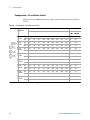
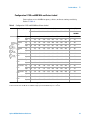
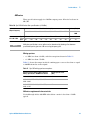
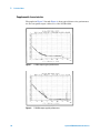
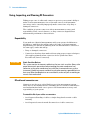
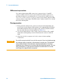
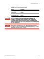
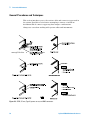
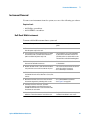
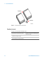
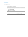
1
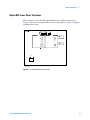
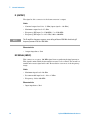
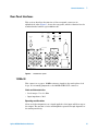
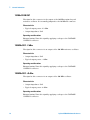
Agilent N5508A
Microwave Source
Hardware Reference
Second edition, May 2012
Agilent Technologies
Notices
© Agilent Technologies, Inc. 2004-2012
Manual Part Number
No part of this manual may be reproduced
in any form or by any means (including
electronic storage and retrieval or translation into a foreign language) without prior
agreement and written consent from Agilent Technologies, Inc. as governed by
United States and international copyright
laws.
N5508-90001
Edition
Second edition, May 2012
Printed in USA
Agilent Technologies, Inc.
1400 Fountaingrove Pkwy
Santa Rosa, CA 95403
Warranty
The material contained in this document is provided “as is,” and is subject to being changed, without notice,
in future editions. Further, to the maximum extent permitted by applicable
law, Agilent disclaims all warranties,
either express or implied, with regard
to this manual and any information
contained herein, including but not
limited to the implied warranties of
merchantability and fitness for a particular purpose. Agilent shall not be
liable for errors or for incidental or
consequential damages in connection
with the furnishing, use, or performance of this document or of any
information contained herein. Should
Agilent and the user have a separate
written agreement with warranty
terms covering the material in this
document that conflict with these
terms, the warranty terms in the separate agreement shall control.
Technology Licenses
The hardware and/or software described in
this document are furnished under a
license and may be used or copied only in
accordance with the terms of such license.
Restricted Rights Legend
If software is for use in the performance of
a U.S. Government prime contract or subcontract, Software is delivered and
licensed as “Commercial computer software” as defined in DFAR 252.227-7014
(June 1995), or as a “commercial item” as
defined in FAR 2.101(a) or as “Restricted
computer software” as defined in FAR
52.227-19 (June 1987) or any equivalent
agency regulation or contract clause. Use,
duplication or disclosure of Software is
subject to Agilent Technologies’ standard
commercial license terms, and non-DOD
Departments and Agencies of the U.S. Government will receive no greater than
Restricted Rights as defined in FAR
52.227-19(c)(1-2) (June 1987). U.S. Government users will receive no greater than
Limited Rights as defined in FAR 52.227-14
(June 1987) or DFAR 252.227-7015 (b)(2)
(November 1995), as applicable in any
technical data.
Safety Notices
C A UTI ON
A CAUTION notice denotes a hazard. It calls attention to an operating procedure, practice, or the like
that, if not correctly performed or
adhered to, could result in damage
to the product or loss of important
data. Do not proceed beyond a
CAUTION notice until the indicated
conditions are fully understood and
met.
WA RN IN G
A WARNING notice denotes a
hazard. It calls attention to an
operating procedure, practice, or
the like that, if not correctly performed or adhered to, could result
in personal injury or death. Do not
proceed beyond a WARNING
notice until the indicated conditions are fully understood and met.
Contents
1 General Information
Overview 8
Figure 1. N5508A microwave source
Option 002 9
Figure 2. N5508A microwave source
Standard Model Front-Panel Interfaces
Figure 3. N5508A front panel 10
ACT (STATUS) 10
ERR (STATUS) 10
LSN (GPIB) 10
POWER 11
RMT (GPIB) 11
SRQ (GPIB) 11
TLK (GPIB) 11
mW LO (OUTPUT) 11
VOLTAGE CONTROL (INPUT) 12
8
9
10
Option 002 Front-Panel Interfaces 13
Figure 4. N5508A Option 002 front panel
IF (OUTPUT) 14
RF SIGNAL (INPUT) 14
13
Rear-Panel Interfaces 15
Figure 5. N5508A rear panel 15
10 MHz IN 15
10 MHz OVEN OUT 16
100 MHz OUT: -2 dBm 16
100 MHz OUT: +8 dBm 16
600 MHz OUT: 0 dBm 17
600 MHz OUT: +20 dBm 17
Buffered 10 MHz Out 17
GPIB 17
IF LEVEL 18
Power Connector (~ LINE) 18
MULTIPLEXER: OUT 18
TUNE SPAN OUT 18
Agilent N5508A Hardware Reference
3
2 Technical Data
General Specifications 20
Table 1. Environmental and mechanical specifications
20
Standard Model Specifications 21
RF output 21
Table 2. RF output specifications 21
Spectral purity 21
Configuration 1: all oscillators locked 22
Table 3. Configuration 1: all oscillators locked 22
Configuration 2: 100 and 600 MHz oscillators locked 23
Table 4. Configuration 2: 100 and 600 MHz oscillators locked 23
Configuration 3: 600 MHz free-running oscillator 24
Table 5. Configuration 3: 600 MHz free-running oscillator 24
AM noise 25
Table 6. AM detector noise floor specifications (+10 dBm) 25
25
Supplemental characteristics 25
Table 7. RF output supplemental characteristics 25
Figure 6. Maximum output power vs. frequency graph 26
Option 002 Specifications 27
RF output 27
Table 8. Opt. 002 RF output specifications 27
RF source 27
Spectral purity 27
Configuration 1: all oscillators locked 28
Table 9. Opt. 002 configuration 1 - all oscillators locked 28
AM noise 29
Table 10. Opt. 002 AM noise floor specifications (+10 dBm) 29
Table 11. Opt. 002 mixing spurious exceptions 29
Supplemental characteristics 30
Figure 7. 10 MHz output typical performance 30
Figure 8. 100 MHz output typical performance 30
Figure 9. 600 MHz output typical performance 31
3 Preventive Maintenance
Using, Inspecting, and Cleaning RF Connectors
Repeatability 34
RF cable and connector care 34
Proper connector torque 35
Table 12. Proper Connector Torque 35
4
34
Agilent N5508A Hardware Reference
Connector wear and damage 35
SMA connector precautions 36
Cleaning procedure 36
Table 13. Cleaning Supplies Available from Agilent
37
General Procedures and Techniques 38
Figure 10. GPIB, 3.5 mm, Type-N, power sensor, and BNC connectors
Connector removal 39
38
Instrument Removal 41
Half-Rack-Width instrument 41
To remove a half-width instrument from a system rack 41
Figure 11. Instrument lock links, front and rear 42
Benchtop instrument 42
To remove an instrument from a benchtop system 42
Instrument Installation 43
Half-Rack-Width instrument 43
To install the instrument in a rack 43
Benchtop instrument 44
To install an instrument in a benchtop system 44
Agilent N5508A Hardware Reference
5
6
Agilent N5508A Hardware Reference
N5508A Microwave Source
Hardware Reference
1
General Information
Overview 8
Standard Model Front-Panel Interfaces 10
Option 002 Front-Panel Interfaces 13
Rear-Panel Interfaces 15
Agilent Technologies
7
1
General Information
Overview
The Agilent N5508A programmable microwave source is a half-rack-width
System II unit that ouputs a signal between 2.4 GHz and 26.4 GHz in 600 MHz
steps. The signals are output at levels from 0 dBm up to +16 dBm (+10 dBm
above 7.2 GHz).
The signal is derived from a 600 MHz oscillator which either free-runs or is
phase-locked to a reference chain. The reference chain consists of a 100 MHz
oscillator, which can be the reference or it can be phased-locked to a 10 MHz
crystal controlled reference. A voltage applied to the VOLTAGE CONTROL
connector can tune the reference chain.
A step-recovery-diode multiplies the 600 MHz and a YIG-tuned-filter (YTF)
picks off the desired frequency. The output of the YTF is amplified by a gain
adjustable amplifier. This amplifier has two operating modes. One mode is for
minimum noise, and the other lowers high order harmonics.
.
Figure 1
8
N5508A microwave source
Agilent N5508A Hardware Reference
General Information
1
Option 002
Option 002 adds tunable source capability to the N5508A unit. It upconverts a
synthesized signal generator’s output into the 2.4 GHz to 26.5 GHz range. It
has the same microwave source as the standard unit and a mixer with a second
YIG-tuned filter. The tunable source can also function in the E5505A phase
noise measurement system as a microwave source.
Figure 2
N5508A microwave source
Agilent N5508A Hardware Reference
9
1
General Information
Standard Model Front-Panel Interfaces
This section describes the function of the front-panel interfaces on the N5508A
downconverter. Figure 3 shows the front panel. The interface descriptions
appear in alphabetical order.
N5508A
2.4-25.8 GHz
Microwave Source
RMT
GPIB
LSN TLK
INPUT
SRQ
STATUS
ACT ERR
OUTPUT
VOLTAGE
CONTROL
W LO
POSSIBLE
OUTPUT POWER
+23 dBm
10 VOLTS MAX
2.4 - 25.8 GHz
POWER
n5508a_front_pnl
27 Apr 04 rev 1
Figure 3
NO T E
N5508A front panel
Some interfaces on the front and rear panels are not used for phase noise measurement, as
their descriptions indicate. Their primary function is for factory testing and troubleshooting.
ACT (STATUS)
This LED is not used for phase noise measurements.
ERR (STATUS)
The error message LED illuminates when a communication error occurs and
indicates that an error message is available.
LSN (GPIB)
The listen LED illuminates when the system addresses the instrument to
listen.
10
Agilent N5508A Hardware Reference
1
General Information
POWER
This switch puts the instrument in active operation or standby mode. It is a
standby switch and not a LINE switch. The detachable power cord is the test
set’s disconnecting device. It disconnects the mains circuits from the mains
supply before other parts of the instrument or system.
RMT (GPIB)
The remote indicator LED illuminates when the unit is enabled for GPIB
control.
SRQ (GPIB)
The service request LED illuminates when the instrument requests service.
TLK (GPIB)
The talk indicator LED illuminates when the system addresses the instrument
to talk.
µW LO (OUTPUT)
The signal at this connector is the source’s output.
Limits
• Frequency range: 2.4 to 25.8 GHz, in 600 MHz steps
• Output power (2.4 to 6.6 GHz): 0 to +16 dBm
• Output power (7.2 to 25.8 GHz): 0 to +10 dBm
Characteristics
• Output impedance: 50 Ω
Agilent N5508A Hardware Reference
11
1
General Information
VOLTAGE CONTROL (INPUT)
This connector accepts an external tuning voltage from the phase noise test set
for the 10, 100, or 600 MHz oscillators.
Limits
• Maximum voltage: ±10 V
• Maximum frequency shift (10 MHz): ±0.25 ppm
• Maximum frequency shift (100 MHz): ±5 ppm
• Maximum frequency shift (600 MHz): ±100 ppm
Characteristics
• Input impedance: 100 kΩ
12
Agilent N5508A Hardware Reference
1
General Information
Option 002 Front-Panel Interfaces
The front-panel on the N5508A Option 002 has two additional interfaces.
Figure 4 shows the front panel. The interface descriptions on page 14 appear
in alphabetical order.
N5508A Opt 002
Microwave Source
RMT
GPIB
LSN TLK
SRQ
STATUS
ACT ERR
INPUT
OUTPUT
RF SIGNAL
RF
0 TO +5 dBm
2.4-26.5 GHz
VOLTAGE
CONTROL
POSSIBLE
OUTPUT POWER
+23 dBm
W LO
POSSIBLE
OUTPUT POWER
+23 dBm
10 VOLTS MAX
2.4 - 25.8 GHz
POWER
n5508a_opt002_front_pnl
27 Apr 04 rev 1
Figure 4
N5508A Option 002 front panel
Agilent N5508A Hardware Reference
13
1
General Information
IF (OUTPUT)
The signal at this connector is the downconverter’s output.
Limits
• Nominal output level: 0 to +5 dBm (input signal ≥ –30 dBm)
• Maximum output level: +15 dBm
• Frequency (RF input 5 to 1500 MHz): 5 to 1500 MHz
• Frequency (RF input 5 to 26.5 GHz): 300 to 900 MHz
NO T E
The IF amplifiers frequency response starts rolling off above 1200 MHz. Avoid using IF
frequency between 1200 and 1500 MHz.
Characteristics
• Output impedance: 50 Ω
RF SIGNAL (INPUT)
This connector accepts a 120 MHz signal from a synthesized signal generator.
This signal is mixed with the internal microwave local oscillator. The result is a
tunable microwave signal with a 0.1 Hz resolution over most of the frequency
range.
Limits
• Maximum input level: +10 dBm
• Recommended input level: –10 to +5 dBm
• Frequency: 120 to 900 MHz
Characteristics
• Input impedance: 50 Ω
14
Agilent N5508A Hardware Reference
General Information
1
Rear-Panel Interfaces
This section describes the function of the rear-panel connectors in
alphabetical order. Figure 5 shows the rear panel, which is identical for the
standard model and the option 002 model.
10 MHz IN
100 MHz OUT
+8 dBm
-2 dBm
BUFFERED
10 MHz OUT
600 MHz OUT
+20 dBm
0 dBm
10 MHz OVEN
OUT
TUNE SPAN
OUT
GPIB
MULTIPLEXER
OUT
SEE USERS MANUAL
ICES/NMB-001
ISM GRP.1 CLASS A
N10149
SERIAL NUMBER
LABEL
154258
LINE
115 V/3 A
230 V/2 A
50/60 Hz
FUSE: T 3.15 A 250 V
n5508a_opt002_rear_pnl
27 Apr 04 rev 1
Figure 5
N5508A rear panel
10 MHz IN
This connector accepts a 10 MHz reference signal for the unit’s phase lock
loops. It is normally jumpered to the 10 MHz OVEN OUT connector.
Limits and characteristics
• Level range: +7 to +13 dBm
• Input impedance: 50 Ω
Operating considerations
Noise and other impurities on a signal applied to this input will show up on
the output. The amount of noise and impurities passed through depends on
the tuning sensitivity.
Agilent N5508A Hardware Reference
15
1
General Information
10 MHz OVEN OUT
The signal at this connector is the output of the 10 MHz ovenized crystal
reference oscillator. It is normally jumpered to the 10 MHz IN connector.
Characteristics
• Typical output power: +13 dBm
• Output impedance: 50 Ω
Operating considerations
External tuning: Tune this signal by applying a voltage to the VOLTAGE
CONTROL connector.
100 MHz OUT: -2 dBm
The signal at this connector is an output of the 100 MHz reference oscillator.
Characteristics
• Output impedance: 50 Ω
• Typical output power: –2 dBm
Operating considerations
External tuning: Tune this signal by applying a voltage to the VOLTAGE
CONTROL connector.
100 MHz OUT: +8 dBm
The signal at this connector is an output of the 100 MHz oscillator.
Characteristics
• Output impedance: 50 Ω
• Typical output power: +8 dBm
Operating considerations
External tuning: Tune this signal by applying a voltage to the VOLTAGE
CONTROL connector.
16
Agilent N5508A Hardware Reference
1
General Information
600 MHz OUT: 0 dBm
The signal at this connector is an output of the 600 MHz Output oscillator.
Characteristics
• Output impedance: 50 Ω
• Typical output power: 0 dBm
Operating considerations
External tuning: Tune this frequency by applying a voltage to the VOLTAGE
CONTROL connector.
600 MHz OUT: +20 dBm
The signal at this connector is an output of the 600 MHz oscillator.
Characteristics
• Output impedance: 50 Ω
• Typical output power: +20 dBm
Operating considerations
External tuning: Tune this signal by applying a voltage to the VOLTAGE
CONTROL connector.
Buffered 10 MHz Out
The signal at this connector is the signal at the rear-panel 10 MHz IN connector
after it has been buffered by an amplifier.
Characteristics
• Output impedance: 50 Ω
• Typical output power: +7 dBm
Operating considerations
When the reference chain tuning sensitivity is set to 1.0 ppm/V, this output is
switched off.
GPIB
GPIB communication between the source and the system occurs through this
connection.
Agilent N5508A Hardware Reference
17
1
General Information
IF LEVEL
This output connector is not used for phase noise measurements.
Power Connector (~ LINE)
This is the connection for the AC power cord. The detachable power cord is the
test set’s disconnecting device. It disconnects the mains circuits from the
mains supply before other parts of the instrument or system. For information
on power requirements, see “General Specifications" on page 20.
MULTIPLEXER: OUT
The signal at this connector is the voltage that is measured by the internal
voltmeter.
Characteristics
• Output level range: ±10 V
• Output impedance: 1 kΩ
• Bandwidth: 100 kHz
TUNE SPAN OUT
This connector is not used for phase noise measurement.
18
Agilent N5508A Hardware Reference
N5508A Microwave Source
Hardware Reference
2
Technical Data
General Specifications 20
Standard Model Specifications 21
Option 002 Specifications 27
Agilent Technologies
19
2
Technical Data
General Specifications
This section contains environmental, mechanical, RF input, and IF ouput
specifications and supplemental characteristics for the N5508A microwave
source.
Specifications describe the instrument’s warranted performance and apply
after the warm-up period. These specifications are valid over the instrument’s
operating/environmental range unless otherwise noted.
Supplemental Characteristics provide additional information that is useful
for operating the instrument by giving typical (expected), but not warranted,
performance parameters.
The specifications in Table 1 apply to both the N5508A standard model and
Option 002.
Table 1
20
Environmental and mechanical specifications
Altitude
Up to 2,000 meters (6,500 ft)
Operating temperature range
+0 °C to +45 °C (32 ° F to 113 ° F)
Warm-up time
20 minutes
Max relative humidity
80% for temperatures up to 31 °C, decreasing linearly
to 50% relative humidity at 40 °C.
Height
177.2 mm (7 in)
Width
212.5 mm (8.4 in)
Depth
574.3 mm (22.6 in)
Weight
~ 33.5 lbs (15.2 kg)
Agilent N5508A Hardware Reference
Technical Data
2
Standard Model Specifications
RF output
Table 2
RF output specifications
Frequency Range
2.4 to 25.8 GHz
Frequency Resolution
600 MHz
Ouput Power:
• 2.4 to 6.6 GHz
• 7.2 to 25.8 GHz
0 to +16 dBm
0 to +10 dBm
Spectral purity
The internal reference oscillators of the N5508A can be locked together in
three configurations, each with different phase noise performance and tuning
bandwidths. Table 3 on page 22 through Table 5 on page 24 provide the
specifications for each configuration. All noise levels are in units of dBc/Hz
unless otherwise noted.
Agilent N5508A Hardware Reference
21
2
Technical Data
Configuration 1: all oscillators locked
Best phase noise <100 Hz frequency offsets, narrow tuning sensitivity. Refer to
Table 3.
Table 3
Configuration 1: all oscillators locked
Output
Frequency
Offset From Carrier (Hz)
Spurious (dBc)
11
10
100
1k
10k
100k
1M
10M
40M
10
to 100
1k to
100 MHz
2.4 to
3.0 GHz
Typ.
–50
–80
–100
–128
–138
–148
–152
–152
–152
–60
–80
Spec.
–45
–75
–95
–123
–133
–143
–147
–147
–147
–50
–70
3.0 to
4.2 GHz
Typ.
–47
–77
–97
–125
–136
–146
–150
–150
–150
–54
–80
Spec.
–42
–72
–92
–120
–131
–141
–145
–145
–145
–44
–70
4.2 to
6.0 GHz
Typ.
–44
–74
–94
–122
–134
–144
–148
–148
–148
–54
–80
Spec.
–39
–69
–89
–117
–129
–139
–143
–143
–143
–44
–70
6.0 to
7.8 GHz
Typ.
–42
–72
–92
–120
–132
–143
–147
–147
–147
–54
–80
Spec.
–37
–67
–87
–115
–127
–138
–142
–142
–142
–44
–70
7.8 to
Typ.
10.2 GHz
Spec.
–40
–70
–90
–118
–130
–141
–145
–145
–145
–50
–80
–35
–65
–85
–113
–125
–136
–140
–140
–140
–40
–70
10.2 to
Typ.
12.6 GHz
Spec.
–38
–68
–88
–116
–128
–140
–143
–143
–143
–50
–80
–33
–63
–83
–111
–123
–135
–138
–138
–138
–40
–70
12.6 to
Typ.
18.0 GHz
Spec.
–35
–65
–85
–113
–125
–137
–140
–140
–140
–47
–70
–30
–60
–80
–108
–120
–132
–135
–135
–135
–37
–60
18.0 to
Typ.
25.8 GHz
Spec.
–32
–62
–82
–110
–122
–134
–136
–136
–136
–44
–70
–27
–57
–77
–105
–117
–129
–131
–131
–131
–34
–60
1 All noise levels above -30 dBc/Hz are 3 dB below Sφ(f) expressed in dB with respect to 1 rad2/Hz.
22
Agilent N5508A Hardware Reference
Technical Data
2
Configuration 2: 100 and 600 MHz oscillators locked
Better phase noise <10 kHz frequency offsets, moderate tuning sensitivity.
Refer to Table 4.
Table 4
Configuration 2: 100 and 600 MHz oscillators locked
Output Frequency
Offset From Carrier (Hz)
11
10 2
100
1k
10k
+2
–48
–98
–128
100k
Spurious (dBc)
1M
10M
40M
100
1k to
100 MHz
–138 –148
–152
–152
–145
–60
–80
2.4 to 3.0
GHz
Typ.
Spec. +7
–43
–93
–123
–133 –143
–147
–147
–147
–50
–70
3.0 to 4.2
GHz
Typ.
–45
–95
–125
–136 –146
–150
–150
–150
–54
–80
Spec. +10
–40
–90
–120
–131 –141
–145
–145
–145
–44
–70
4.2 to 6.0
GHz
Typ.
–42
–92
–122
–134 –144
–148
–148
–148
–54
–80
Spec. +13
–37
–87
–117
–129 –139
–143
–143
–143
–44
–70
6.0 to 7.8
GHz
Typ.
+10
–40
–90
–120
–132 –143
–147
–147
–147
–54
–80
Spec. +15
–35
–85
–115
–127 –138
–142
–142
–142
–44
–70
7.8 to 10.2
GHz
Typ.
+12
–38
–88
–118
–130 –141
–145
–145
–145
–50
–80
Spec. +17
–33
–83
–113
–125 –136
–140
–140
–140
–40
–70
10.2 to 12.6
GHz
Typ.
+14
–36
–86
–116
–128 –140
–143
–143
–143
–50
–50
Spec. +19
–31
–81
–111
–123 –135
–138
–138
–138
–40
–70
12.6 to 18.0
GHz
Typ.
+17
–33
–83
–113
–125 –137
–140
–140
–140
–47
–70
Spec. +22
–28
–78
–108
–120 –132
–135
–135
–135
–37
–60
18.0 to 25.8
GHz
Typ.
+20
–30
–80
–110
–122 –134
–136
–136
–136
–44
–70
Spec. +25
–25
–75
–105
–117 –129
–131
–131
–131
–34
–60
+5
+8
1 All noise levels above -30 dBc/Hz are 3 dB below Sφ(f) expressed in dB with respect to 1 rad2/Hz.
2 All noise levels above -40 dBc/Hz are 3 dB below Sφ(f) expressed in dB with respect to 1 rad2/Hz.
Agilent N5508A Hardware Reference
23
2
Technical Data
Configuration 3: 600 MHz free-running oscillator
Good phase noise <10 kHz frequency offsets, wide tuning sensitivity. Refer to
Table 5.
Table 5
k
Configuration 3: 600 MHz free-running oscillator
Output
Frequency
Offset From Carrier (Hz)
2.4 to
3.0 GHz
Typ.
3.0 to
4.2 GHz
Typ.
4.2 to
6.0 GHz
Typ.
6.0 to
7.8 GHz
Typ.
Spurious (dBc)
11
10 2
100
1k
+15
–35
–75
–109 –138 –148 –152 –152 –152 –40
–80
–80
–105 –133 –143 –147 –147 –147 –30
–70
–70
–107 –136 –146 –150 –150 –150 –34
–74
–80
–103 –131 –141 –145 –145 –145 –24
–64
–70
–105 –134 –144 –148 –148 –148 –34
–74
–80
–101 –129 –139 –142 –142 –142 –24
–64
–70
–102 –132 –143 –147 –147 –147 –34
–74
–80
–98
–127 –138 –142 –142 –142 –24
–64
–70
–98
–130 –141 –145 –145 –145 –30
–70
–80
–94
–125 –136 –140 –140 –140 –20
–60
–70
–95
–128 –140 –143 –143 –143 –30
–70
–80
–91
–123 –135 –138 –138 –138 –20
–60
–70
–92
–125 –137 –140 –140 –140 –27
–67
–70
–88
–120 –132 –135 –135 –135 –17
–57
–60
–89
–122 –134 –136 –136 –136 –24
–64
–70
–85
–117 –129 –131 –131 –131 –14
–54
–60
Spec.
+18
–32
–72
Spec.
+21
–29
–69
Spec.
+23
–27
–67
Spec.
7.8 to
Typ.
10.2 GHz
Spec.
+25
10.2 to
Typ.
12.6 GHz
Spec.
+27
12.6 to
Typ.
18.0 GHz
Spec.
+30
18.0 to
Typ.
26.5 GHz
Spec.
+33
–25
–23
–20
–17
–65
–63
–60
–57
10k
100k 1M
10M 40M
100
1k
≥10k
1 All noise levels above -30 dBc/Hz are 3 dB below Sφ(f) expressed in dB with respect to 1 rad2/Hz.
2 All noise levels above -40 dBc/Hz are 3 dB below Sφ(f) expressed in dB with respect to 1 rad2/Hz.
24
Agilent N5508A Hardware Reference
2
Technical Data
AM noise
Specifications apply for +10 dBm output power. All noise levels are in units of
dBc/Hz. Refer to Table 6.
Table 6
AM detector noise floor specifications (+10 dBm)
Output Frequency
2.4 to 25.8
GHz
Offset From Carrier (Hz)
Spurious (dBc)
1
10
100
1k
10k
100k
1M
10M
40M
10
Typ.
–100
–110
–117
–133
–143
–153
–155
–155
–155
–60 –80
Spec.
–95
–105
–112
–128
–138
–148
–150
–150
–150
–50 –70
NO T E
1k to 40M
AM noise specifications at any offset can be determined by drawing a line between
specification points given on a dB-versus-log frequency plot.
Supplemental characteristics
Table 7
RF output supplemental characteristics
Frequency Overrange
26.4 GHz with degraded output power
Output Level Entry Resolution
0.1 dB
Absolute Power Accuracy
±3 dB
Harmonics
–10 dBc
Frequency Switching Transients
Output power can peak at +22 dBm during frequency
switching
Output Power Drift
<1 dB after warm-up (20 min)
Output Power Settling Time
<100 ms
Frequency Switching Speed:
• Standard
• Option 002
3 seconds
6 seconds
Reference Tuning
Agilent N5508A Hardware Reference
Voltage control of the internal reference oscillators is
available through a port on the front panel.
25
2
Technical Data
Table 7
RF output supplemental characteristics (continued)
Tuning Range (sensitivity)
Configuration 1
• ±0.25 ppm (0.05 ppm/volt)
Configuration 2
• ±5 ppm (1 ppm/volt)
Configuration 3
• ±100 ppm (20 ppm/volt)
Tuning Port Voltage Range
±5 volts (overrange ±10 volts)
Tuning Port Input Impedance
• 2 kΩ
Maximum Output Power vs. Frequency
Figure 6
26
Maximum output power vs. frequency graph
Agilent N5508A Hardware Reference
Technical Data
2
Option 002 Specifications
RF output
Table 8
Opt. 002 RF output specifications
Frequency Range
Frequency Resolution:
0.1 Hz
Ouput Power:
o 2.4 to 6.6 GHz
o 7.2 to 25.8 GHz
o 25.8 to 26.5 GHz
2.4 to 25.8 GHz
2.4 to 26.5 GHz
Exceptions:
o 0.2 Hz: 25.84 GHz ≤ Carrier Frequency <26.1 GHz
o 0.2 Hz: 26.44 GHz ≤ Carrier Frequency ≤26.5 GHz
0 to +16 dBm
0 to +10 dBm
0 to +7 dBm
RF source
With N5508A Option 002, the phase noise measurement system requires the
addition of a synthesized signal generator. The signal generator adds the
capability of mixing an RF source with the microwave source. The front-panel
frequency of the RF source is automatically controlled by the N5508A unit.
Spectral purity
The spectral purity table (Table 9 on page 28) combines the N5508A Option
002 configuration 1 with the 8662A or 8663A synthesized signal generators
when used as a microwave source. All noise levels are in units of dBc/Hz
unless otherwise noted.
To combine the 8662A/3A phase noise specifications with configuration 2
specifications (Table 4 on page 23) and/or configuration 3 specifications
(Table 5 on page 24), use the phase noise numbers from Table 9 for offsets
≥1 kHz and configuration 2 and 3 tables for offsets ≤100 Hz.
Agilent N5508A Hardware Reference
27
2
Technical Data
Configuration 1: all oscillators locked
Best phase noise <100 Hz frequency offsets, narrow tuning sensitivity. Refer to
Table 9.
Table 9
Opt. 002 configuration 1 - all oscillators locked
Output
Frequency
Spurious (dBc)1
Offset From Carrier (Hz)
12
10
100
–50
–80
–100 –119 –121 –124 –130 –130 –135 –147 –147
–60
–80
1k
3k
5k
10k
100k 1M
10M 40M
10 to 1k to
100 100 MHz
2.4 to
3.0 GHz
Typ.
Spec. –43
–73
–92
–112 –112 –114 –124 –124 –130 –142 –142
–50
–70
3.0 to
4.2 GHz
Typ.
–47
–77
–97
–122 –129 –130 –133 –136 –141 –149 –149
–54
–80
Spec. –42
–72
–92
–115 –117 –120 –128 –131 –136 –144 –144
–44
–70
4.2 to
6.0 GHz
Typ.
–44
–74
–94
–120 –123 –124 –131 –136 –141 –148 –148
–54
–80
Spec. –39
–69
–89
–114 –117 –119 –126 –131 –136 –143 –143
–44
–70
6.0 to
7.8 GHz
Typ.
–42
–72
–92
–119 –123 –125 –130 –136 –140 –147 –147
–54
–80
Spec. –37
–67
–87
–113 –116 –118 –125 –131 –135 –142 –142
–44
–70
7.8 to
10.2
GHz
Typ.
–40
–70
–90
–118 –121 –124 –129 –135 –139 –145 –145
–50
–80
Spec. –35
–65
–85
–112 –115 –117 –124 –130 –134 –140 –140
–40
–70
10.2 to
12.6
GHz
Typ.
–38
–68
–88
–116 –121 –123 128
–134 –138 –143 –143
–50
–80
Spec. –33
–63
–83
–111 –114 –116 –123 –129 –133 –138 –138
–40
–70
12.6 to
18.0
GHz
Typ.
–35
–65
–85
–113 –119 –121 –125 –133 –137 –140 –140
–47
–70
Spec. –30
–60
–80
–108 –112 –114 –120 –128 –132 –135 –135
–37
–60
18.0 to
26.5
GHz
Typ.
–32
–62
–82
–110 –115 –117 –122 –128 –133 –136 –136
–44
–70
Spec. –27
–57
–77
–105 –108 –110 –117 –123 –127 –131 –131
–34
–60
1 Mixing an RF source with the microwave LO in the N5508A Option 002 may result in some mixing spurious exceeding spurious
specifications, see Table 11, “Opt. 002 mixing spurious exceptions,” on page 29.
2 All noise levels above -30 dBc/Hz are 3 dB below Sφ(f) expressed in dB with respect to 1 rad2/Hz.
28
Agilent N5508A Hardware Reference
Technical Data
2
AM noise
These specifications apply for +10 dBm output power. All noise levels are in
dBc/Hz.
Table 10 Opt. 002 AM noise floor specifications (+10 dBm)
Option 002
Output Frequency
Offset From Carrier (Hz)
1
10
100
1k
10k
100k
1M
10M
40M
10
1k to
40M
–97
–107
–114
–130
–140
–150
–152
–152
–152
–60
–80
Spec. –92
–102
–109
–125
–135
–145
–147
–147
–147
–50
–70
Typ.
2.4 to 26.5 GHz
NO T E
Spurious (dBc)
AM noise specifications at any offset can be determined by drawing a line between
specification points given on a dB-versus-log frequency plot.
Mixing spurious
• < 6 GHz: less than –60 dBc, with the exceptions shown in Table 11.
• > 6 GHz: less than –70 dBc
Table 11 shows the ranges in which a mixing spur occurs at less than or equal
to 40 MHz from the carrier signal.
Table 11 Opt. 002 mixing spurious exceptions
Carrier Frequency Range (GHz)in which a
Mixing Spur Occurs ≤40 MHz from Carrier
Typical Spurious Level
(dBc)
2.990 - 3.010
–40
2.392 - 2.408, 2.737 - 2.749, 2.793 - 2.807
3.592 - 3.608
–60
2.493 - 2.507, 2.929 - 2.938, 3.493 - 3.507,
4.109 - 4.120
–70
AM noise supplemental characteristics
LO feedthrough 430 to 480 MHz offset below carrier is less than –50 dBc
typical.
Agilent N5508A Hardware Reference
29
2
Technical Data
Supplemental characteristics
The graphs in Figure 7 through Figure 9 show typical phase noise performance
for the rear-panel output connectors of the N5508A unit.
30
Figure 7
10 MHz output typical performance
Figure 8
100 MHz output typical performance
Agilent N5508A Hardware Reference
Technical Data
Figure 9
2
600 MHz output typical performance
Agilent N5508A Hardware Reference
31
2
32
Technical Data
Agilent N5508A Hardware Reference
N5508A Microwave Source
Hardware Reference
3
Preventive Maintenance
Using, Inspecting, and Cleaning RF Connectors 34
General Procedures and Techniques 38
Instrument Removal 41
Instrument Installation 43
Agilent Technologies
33
3
Preventive Maintenance
Using, Inspecting, and Cleaning RF Connectors
Taking proper care of cables and connectors protects your system’s ability to
make accurate measurements. One of the main sources of measurement
inaccuracy can be caused by improperly made connections or by dirty or
damaged connectors.
The condition of system connectors affects measurement accuracy and
repeatability. Worn, out-of-tolerance, or dirty connectors degrade these
measurement performance characteristics.
Repeatability
If you make two identical measurements with your system, the differences
should be so small that they will not affect the value of the measurement.
Repeatability (the amount of similarity from one measurement to another of
the same type) can be affected by:
• Dirty or damaged connectors
• Connections that have been made without using proper torque techniques
(this applies primarily when connectors in the system have been
disconnected, then reconnected).
C A UTI ON
Static-Sensitive Devices
This system contains instruments and devices that are static-sensitive. Always take
proper electrostatic precautions before touching the center conductor of any
connector, or the center conductor of any cable that is connected to any system
instrument. Handle instruments and devices only when wearing a grounded wrist or
foot strap. When handling devices on a work bench, make sure you are working on
an anti-static worksurface.
RF cable and connector care
Connectors are the most critical link in a precision measurement system.
These devices are manufactured to extremely precise tolerances and must be
used and maintained with care to protect the measurement accuracy and
repeatability of your system.
To extend the life of your cables or connectors:
• Avoid repeated bending of cables—a single sharp bend can ruin a cable
instantly.
• Avoid repeated connection and disconnection of cable connectors.
34
Agilent N5508A Hardware Reference
Preventive Maintenance
3
• Inspect the connectors before connection; look for dirt, nicks, and other
signs of damage or wear. A bad connector can ruin the good connector
instantly.
• Clean dirty connectors. Dirt and foreign matter can cause poor electrical
connections and may damage the connector.
• Minimize the number of times you bend cables.
• Never bend a cable at a sharp angle.
• Do not bend cables near the connectors.
• If any of the cables will be flexed repeatedly, buy a back-up cable. This will
allow immediate replacement and will minimize system down time.
Before connecting the cables to any device:
• Check all connectors for wear or dirt.
• When making the connection, torque the connector to the proper value.
Proper connector torque
• Provides more accurate measurements
• Keeps moisture out of the connectors
• Eliminates radio frequency interference (RFI) from affecting your
measurements
The torque required depends on the type of connector. Refer to Table 12.
Do not overtighten the connector.
Never exceed the recommended torque when attaching cables.
Table 12 Proper Connector Torque
Connector
Torque cm-kg
Torque N-cm
Torque in-lbs
Wrench P/N
Type-N
52
508
45
hand tighten
3.5 mm
9.2
90
8
8720-1765
SMA
5.7
56
5
8710-1582
Connector wear and damage
Look for metal particles from the connector threads and other signs of wear
(such as discoloration or roughness). Visible wear can affect measurement
accuracy and repeatability. Discard or repair any device with a damaged
connector. A bad connector can ruin a good connector on the first mating. A
magnifying glass or jeweler’s loupe is useful during inspection.
Agilent N5508A Hardware Reference
35
3
Preventive Maintenance
SMA connector precautions
Use caution when mating SMA connectors to any precision 3.5 mm RF
connector. SMA connectors are not precision devices and are often out of
mechanical tolerances, even when new. An out-of-tolerance SMA connector
can ruin a 3.5 mm connector on the first mating. If in doubt, gauge the SMA
connector before connecting it. The SMA center conductor must never extend
beyond the mating plane.
Cleaning procedure
1 Blow particulate matter from connectors using an environmentally-safe
aerosol such as Aero-Duster. (This product is recommended by the United
States Environmental Protection Agency and contains tetrafluoroethane.
You can order this aerosol from Agilent (see Table 13).)
2 Use alcohol and a lint-free cloth to wipe connector surfaces. Wet a small
swab with a small quantity of alcohol and clean the connector with the
swab.
3 Allow the alcohol to evaporate off of the connector before making
connections.
C A UTI ON
36
Do not allow excessive alcohol to run into the connector. Excessive alcohol entering
the connector collects in pockets in the connector’s internal parts. The liquid will
cause random changes in the connector’s electrical performance. If excessive
alcohol gets into a connector, lay it aside to allow the alcohol to evaporate. This may
take up to three days. If you attach that connector to another device it can take
much longer for trapped alcohol to evaporate.
Agilent N5508A Hardware Reference
Preventive Maintenance
3
Table 13 Cleaning Supplies Available from Agilent
Product
Part Number
Aero-Duster
8500-6460
Isopropyl alcohol
8500-5344
Lint-Free cloths
9310-0039
Small polyurethane swabs
9301-1243
WA RN IN G
Cleaning connectors with alcohol should only be performed with the
instruments’ mains power cord disconnected, in a well ventilated area.
Connector cleaning should be accomplished with the minimum amount of
alcohol. Prior to connector reuse, be sure that all alcohol used has dried, and that
the area is free of fumes.
WA RN IN G
If flammable cleaning materials are used, the material should not be stored, or
left open in the area of the equipment. Adequate ventilation should be assured to
prevent the combustion of fumes, or vapors.
Agilent N5508A Hardware Reference
37
3
Preventive Maintenance
General Procedures and Techniques
This section introduces you to the various cable and connector types used in
the system. Read this section before attempting to remove or install an
instrument! Each connector type may have unique considerations.
Always use care when working with system cables and instruments.
GPIB Type Connector
Figure 10 GPIB, 3.5 mm, Type-N, power sensor, and BNC connectors
38
Agilent N5508A Hardware Reference
3
Preventive Maintenance
Connector removal
GPIB connectors
These are removed by two captured screw, one on each end of the connector;
these usually can be turned by hand. Use a flathead screwdriver if necessary.
GPIB connectors often are stacked two or three deep. When you are removing
multiple GPIB connectors, disconnect each connector one at a time. It is a
good practice to connect them back together even if you have not yet replaced
the instrument; this avoids confusion, especially if more than one instrument
has been removed.
When putting GPIB connectors back on, you must again detach them from one
another and put them on one at a time.
Precision 3.5 mm connectors
These are precision connectors. Always use care when connecting or
disconnecting this type of connector. When reconnecting, make sure you align
the male connector properly. Carefully join the connectors, being careful not
to cross-thread them.
Loosen precision 3.5 mm connectors on flexible cables by turning the
connector nut counter-clockwise with a 5/16 inch wrench. Always reconnect
using an 8 inch-lb torque wrench (Agilent part number 8720-1765). Semirigid
cables are metal tubes, custom-formed for this system from semirigid coax
cable stock.
3.5 mm connectors with a gold hex nut
The semirigid cables that go to the RF outputs of some devices have a gold
connector nut. These do not turn. Instead, the RF connector on the instrument
has a cylindrical connector body that turns. To disconnect this type of
connector, turn the connector body on the instrument clockwise. This action
pushes the cable’s connector out of the instrument connector.
To reconnect, align the cable with the connector on the instrument. Turn the
connector body counterclockwise. You may have to move the cable slightly
until alignment is correct for the connectors to mate. When the two connectors
are properly aligned, turning the instrument’s connector body will pull in the
semirigid cable’s connector. Tighten firmly by hand.
3.5 mm connectors with a silver hex nut
All other semirigid cable connectors use a silver-colored nut that can be
turned. To remove this type of connector, turn the silver nut counter-clockwise
with a 5/16 inch wrench.
Agilent N5508A Hardware Reference
39
3
Preventive Maintenance
When reconnecting this type of cable:
• Carefully insert the male connector center pin into the female connector.
(Make sure the cable is aligned with the instrument connector properly
before joining them.)
• Turn the silver nut clockwise by hand until it is snug, then tighten with an 8
inch-lb torque wrench (part number 8720-1765).
Bent semirigid cables
Semirigid cables are not intended to be bent outside of the factory. An
accidental bend that is slight or gradual may be straightened carefully by hand.
Semirigid cables that are crimped will affect system performance and must be
replaced. Do not attempt to straighten a crimped semirigid cable.
40
Agilent N5508A Hardware Reference
Preventive Maintenance
3
Instrument Removal
To remove an instrument from the system, use one of the following procedures.
Required tools
• #2 Phillips screwdriver
• #2 POZIDRIV screwdriver
Half-Rack-Width instrument
To remove a half-width instrument from a system rack
1 Power off the system.
• For details, see the system installation
guide.
2 Remove the selected instrument’s power cord
from the power strip in the rack.
3 The instrument is attached to the half-rack width
instrument beside it; remove that instrument’s
power cord from the power strip also.
• The instruments are secured together
4 Remove the power cord and other cables from the
front and rear of both instruments.
• Note the location of cables for
5 Remove the four corner screws on the front of the
rack panel that secures the instruments in place.
• The screws are located near the corners
by lock links at the front and rear. The
lock links at the rear attach with screws.
The lock links at the front hook together.
re-installation.
of the face of the instrument.
• Use a #2 Phillips screwdriver.
6 Slide both instruments, as a single unit, out from
the front of the rack and set them on a secure, flat
surface.
7 Detach the lock links that secure the rear of the
instruments together by removing their screws.
• Use a #2 POZIDRIV screwdriver.
• See Figure 11 on page 42.
8 Carefully and at the same time, push one
instrument forward and pull the other back to
unhook the lock links that secure the front of the
instruments to each other.
9 Store the “partner” instrument and lock links
while the selected instrument is out of the rack.
Agilent N5508A Hardware Reference
• Only install the instruments as a pair;
individual installation is not secure.
41
3
Preventive Maintenance
Front links
Rear links
Inst_lock_links
24 Feb 04 rev 1
Figure 11 Instrument lock links, front and rear
Benchtop instrument
To remove an instrument from a benchtop system
1 Power off each instrument in the system.
• For details, see the system installation guide or
system user’s guide.
2 Unplug the selected instrument’s power
cord from the AC power supply.
3 Remove the power cord and other cables
from the front and rear of the instrument.
42
• Note the location of cables for re-installation.
Agilent N5508A Hardware Reference
Preventive Maintenance
3
Instrument Installation
To install or re-install an instrument in a system, use one of the following
procedures.
Required tools
• #2 Phillips screwdriver
• #2 POZIDRIV screwdriver
Half-Rack-Width instrument
To install the instrument in a rack
Step
Note
1 Make sure the system is powered off.
• For details, see the system installation guide
or system user’s guide.
2 Re-attach the lock link that secures the front
of the returned instrument to it’s partner
half-rack-width instrument.
• Use a #2 POZIDRIV screwdriver.
• See Figure 11 on page 42.
3 Re-attach the lock link that secures the rear
of the instruments together.
• Use a #2 POZIDRIV screwdriver.
4 Insert the attached instruments in the same
slot from which you removed them, sliding
them along the support rails until they meet
the rack-mount ears.
• The rack-mount ears stop the instruments at
5 Replace the rack panel in front of the
instruments and secure the four corner
screws.
• The screws are located near the corners of
the correct depth.
the face of the instrument.
• Use a #2 Phillips screwdriver.
6 Confirm that the instrument is turned off.
7 Connect the appropriate cables to the
instruments (front and rear), including the
power cords.
8 Power on the system.
• For details, see the system installation guide
or system user’s guide.
Agilent N5508A Hardware Reference
43
3
Preventive Maintenance
Benchtop instrument
To install an instrument in a benchtop system
1 Make sure the system is powered off.
• For details, see For details, see the system
installation guide or system user’s guide.
2 Connect all cables to the instrument (front
and rear), including the power cord.
3 Connect the power cord to the AC power
source.
4 Power on the system.
• For details, see the system installation guide
or system user’s guide.
5 Set the instrument GPIB address, if
necessary.
44
• For procedures, see the system installation
guide or system user’s guide.
Agilent N5508A Hardware Reference