1
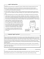
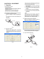
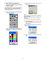
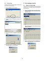
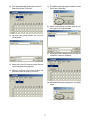
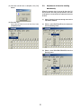
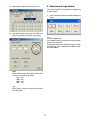
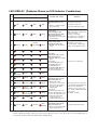
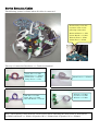
FILE NO. 330-200312
SAFETY PRECAUTION
SERVICE MANUAL
3LCD PROJECTOR
TLP-ET1B
TLP-ET1E
TLP-ET1U
Document Created in Japan Dec. 2003U
SAFETY PRECAUTION
WARNING: Service should not be attempted by anyone unfamiliar with the necessary precautions on this
projector. The following are the necessary precautions to be observed before servicing this chassis.
1 . An isolation Transformer should be connected in the power line between the projector and the AC Iine
before any service is performed on the projector.
2. When replacing a chassis in the cabinet, always be certain that all the protective devices are put back in
place, such as; non-metallic control knobs, insulating covers, shields, isolation resistor-capacitor network
etc.
3. Before returning the set to the customer, always perform an AC Ieakage current check on the exposed
metallic parts of the cabinet, such as terminals, screwheads, metal overlays, control shafts etc. to be sure
the set is safe to operate without danger of electrical shock. Plug the AC Iine cord directly into a AC outlet
(do not use a line isolation transformer during this check). Use an AC voltmeter having 5000ohm per volt or
more sensitivity in the following manner: Connect a1500ohm 10W resistor, paralleled by a 0.15 µF, AC type
capacitor, between a known good earth ground (water
pipe, conduit, etc.) and the exposed metallic parts, one
at a time. Measure the AC voltage across the combination of 1500ohm resistor and 0.15 µF capacitor. Reverse
the AC plug at the AC outlet and repeat AC voltage measurements for each exposed metallic part. Voltage measured must not exceed 5.25V(rms). This corresponds
to 3.5 mA(AC). Any value exceeding this limit constitutes a potential shock hazard and must be corrected
immediately.
PRODUCT SAFETY NOTICE
Many electrical and mechanical parts in this chassis have special safety-related characteristics. These characteristics are often passed unnoticed by a visual inspection and the protection afforded by them cannot necessarily be obtained by using replacement components rated for higher voltage, wattage, etc. Replacement parts
which have these special safety characteristics are identified in this manual and its supplements; electrical
components having such features are identified by the international hazard symbols on the schematic diagram
and the parts list.
Before replacing any of these components, read the parts list in this manual carefully. The use of substitute
replacement parts which do not have the same safety characteristics as specified in the parts list may create
shock, fire or other hazards.
ULTRAVIOLET DANGER IN SERVICE MODE
Eye damage may result from directly viewing the light produced by the lamp used in this product. Always turn
off lamp before opening this cover. Ultraviolet radiation eye protection required during servicing.
TLPB2 Service Manual Rev. 2.0
SAFETY PRECAUTIONS
The lightning flash with arrowhead
symbol, within an equilateral triangle,
is intended to alert the user to the
presence of uninsulated "dangerous
voltage" within the product's
enclosure that may be of sufficient
magnitude to constitute a risk of
electric shock to persons.
The exclamation point within an
equilateral triangle is intended to
alert the user to the presence of
important operating and
maintenance (servicing) instructions
in the literature accompanying the
appliance.
WARNING:
TO REDUCE THE RISK OF FIRE OR ELECTRIC SHOCK, DO NOT EXPOSE THIS
APPLIANCE TO RAIN OR MOISTURE. DANGEROUS HIGH VOLTAGES ARE
PRESENT INSIDETHE ENCLOSURE. DO NOT OPEN THE CABINET. REFER
SERVICING TO QUALIRED PERSONNEL ONLY.
CAUTION:
Laser beam is emitted when the laser button of the remote control is pressed. Do not
look from the front of the remote control. Do not face toward a person or to a mirror.
FCC Radio Frequency Interference Statement
Note:
This equipment has been tested and found to comply with the limits for a Class A
digital device, pursuant to part 15 of the FCC Rules. These limits are designed to
provide reasonable protection against harmful interference when the equipment is
operated in a commercial environment. This equipment generates, uses, and can
radiates radio frequency energy and, if not installed and used in accordance with the
instruction manual, may cause harmful interference to radio communications.
Operation of this equipment in a residential area is likely to cause harmful
interference in which case the user will be required to correct the interference at his
own expense.
WARNING:
Changes or modifications made to this equipment, not expressly approved by
Toshiba, or parties authorized by Toshiba, could void the user's authority to operate
the equipment.
Notice:
This Class A digital apparatus complies with Canadian ICES-003.
Cet appareil numérique de la classe A est conforme à la norme NMB-003 du
Canada.
IMPORTANT PRECAUTIONS
In the spaces provided below, record the Model and Serial No. Iocated
at the rear of your LCD projector.
Save Original Packing Materials
The original shipping carton and packing materials will come in
handy if you ever have to ship your LCD projector. For maximum
protection, repack the set as it was originally packed at the factory.
Mode No.
Serial No.
Retain this information for future reference.
Avoid Volatile Liquid
Do not use volatile liquids, such as an insect spray, near the unit.
Do not leave rubber or plastic products touching the unit for a long
time. They will mar the finish.
Moisture Condensation
Never operate this unit immediately after moving it from a cold
location to a warm location. When the unit is exposed to such a
change in temperature, moisture may condense on the crucial
internal parts. To prevent the unit from possible damage, do not use
the unit for at least 2 hours when there is an extreme or sudden
change in temperature.
I
TLPB2 Service Manual Rev. 2.0
IMPORTANT SAFETY INSTRUCTIONS
CAUTION: PLEASE READ AND OBSERVE
ALLWARNINGS AND
INSTRUCTIONS GIVEN IN THIS
OWNER'S MANUAL AND THOSE
MARKED ON THE UNIT. RETAIN
THIS BOOKLET FOR FUTURE
REFERENCE.
This set has been designed and manufactured
to assure personal safety. Improper use can
result in electric shock or fire hazard. The
safeguards incorporated in this unit will protect
you if you observe the following procedures for
installation, use and servicing. This unit is fully
transistorized and does not contain any parts
that can be repaired by the user.
DO NOT REMOVE THE CABINET COVER, OR
YOU MAY BE EXPOSED TO DANGEROUS
VOLTAGE. REFER SERVICING TO
QUALIFIED SERVICE PERSONNEL ONLY.
1. Read Owner's Manual
After unpacking this product, read the
owner's manual carefully, and follow all
the operating and other instructions.
2.
Power Sources
This product should be operated only from
the type of power source indicated on the
marking label. If you are not sure of the
type of power supply to your home,
consult your product dealer or local power
company.
For products intended to operate from
battery power, or other sources, refer to
the operating instructions.
3. Source of Light
Do not look into the lens while the lamp
is on. The strong light from the lamp may
cause damage to your eyes or sight.
4. Ventilation
Openings in the cabinet are provided for
ventilation and to ensure reliable
operation of the product and to protect it
from overheating, and these openings
must not be blocked or covered. The
openings should never be blocked by
placing the product on a bed, sofa, rug or
other similar surface. This product should
not be placed in a built-in installation such
as a bookcase or rack unless proper
ventilation is provided or the
manufacturer's instructions have been
adhered to.
IMPORTANT SAFETY INSTRUCTIONS
5.
Heat
The product should be situated away from
heat sources such as radiators heat
registers, stoves, or other products
(including amplifiers) that produce heat.
7. Cleaning
Unplug this product from the wall outlet
before cleaning. Do not use liquid cleaners
or aerosol cleaners. Use a damp cloth for
cleaning.
9.
Overloading
Do not overload wall outlets; extension
cords, or integral convenience
receptacles as this can result in a risk of
fire or electric shock.
6.
Water and Moisture
Do not use this product near water - for
example, near a bath tub, wash bowl,
kitchen sink, or laundry tub; in a wet
basement; or near a swimming pool and
the like .
8.
10.
Lightning
For added protection for this product
during storm, or when it is left unattended
and unused for long periods of time,
unplug it from the wall outlet.
This will prevent damage to the product
due to lightning and power-line surges.
Power-Cord Protection
Power-supply cords should be routed so
that they are not likely to be walked on or
pinched by items placed upon or against
them, paying particular attention to cords
at plugs, convenience receptacles, and
the point where they exit from the product.
II
TLPB2 Service Manual Rev. 2.0
IMPORTANT SAFETY INSTRUCTIONS
11.
Object and Liquid Entry
Never push objects of any kind into this
product through openings as they may
touch dangerous voltage points or short-out
parts that could result in a fire or electric
shock. Never spill liquid of any kind on the
product.
13.
Stack Inhibited
Do not stack other equipment on this
product or do not place this product on the
other equipment.
Top and bottom plates of this product
develops heat and may give some
undesirable damage to other unit.
12.
Do not place the product vertically
Do not use the product in the upright
position to project the pictures at the
ceiling, or any other vertical positions.
It may fall down and dangerous.
14.
Attachments
Do not use attachments not recommended
by the product manufacturer as they may
cause hazards.
15.
Accessories
Do not place this product on an unstable
cart, stand, tripod, bracket, or table. The
product may fall, causing serious injury to a
child or adult, and serious damage to the
product. Use only with a cart, stand, tripod,
bracket, or table recommended by the
manufacturer, or sold with the product. Any
mounting of the product should follow the
manufacturer's instructions and should use
a mounting accessory recommended by the
manufacturer.
A product and cart combination should be
moved with care. Quick stops, excessive
force, and uneven surfaces may cause the
product and cart combination to overturn.
IMPORTANT SAFETY INSTRUCTIONS
16. Damage Requiring Service
Unplug this product from the wall outlet and
refer servicing to qualified service
personnel under the following conditions:
a) When the power-supply cord or plug is
damaged.
b) If liquid has been spilled, or objects have
fallen into the product.
c) If the product has been exposed to rain or
water.
d) If the product does not operate normally by
following the operating instructions. Adjust
only those controls that are covered by the
operating instructions as an improper
adjustment of other controls may result in
damage and will often require extensive
work by a qualified technician to restore the
product to its normal operation.
e) If the product has been dropped or
damaged in any way.
f) When the product exhibits a distinct change
in performance - this indicates a need for
service.
17.
Servicing
Do not attempt to service this product
yourself as opening or removing covers
may expose you to dangerous voltage or
other hazards. Refer all servicing to
qualified service personnel.
18.
Replacement Parts
When replacement parts are required, be
sure the service technician has used
replacement parts specified by the
manufacturer or have the same
characteristics as the original part.
Unauthorized substitutions may result in
fire, electric shock, or other hazards.
(Replacement of the lamp only should be
made by users.)
III
19.
Safety Check
Upon completion of any service or repairs
to this product, ask the service technician to
perform safety checks to determine that the
product is in proper operating condition.
TLPB2 Service Manual Rev. 2.0
FILE NO. 330-200312
ELECTRICAL ADJUSTMENT
SERVICE MANUAL
3LCD PROJECTOR
TLP-ET1B
TLP-ET1E
TLP-ET1U
Document Created in Japan Dec. 2003U
. Adjustment software (DPJAdjustmentTool2.exe)
operates following adjustments.
a. Initial setting of keystone correction
(KEYSTONE)
b. Initial adjustment of input signal level (SUB)
c. LCD panel drive center voltage adjustment
(VCOM)
d. LCD panel gamma adjustment (GAMMA)
e. LCD panel color shading adjustment
(SHADING)
ELECTRICAL ADJUSTMENT
1. Preparation
<Test equipment and jigs>
. Personal Computer
(Windows P/C, OS: Windows 95/98, ME, 2000, XP)
. Adjustment software:
(SINGO98.exe, DPJAdjustmentTool2.exe)
. RGB cable, Serial control cable (RS232C)
<For Connection and Setting of Personal Computer>
(1) Connection of personal computer
Connect a computer as shown in following Fig.
1.
Use supplied serial control cable (RS232C) for
connection.
(Note)
When replacing main PC board, adjustment
procedure of item a to e should be applied.
When replacing LCD panel, adjustment
procedure item c to e should be applied.
(3) Setting of communication (COM) port
Select your computer’s COM port (COM1 to
COM4) from COM port pull-down menu.
Control cable
RGB cable
to Signal PC
to Control PC
Fig. 1
(2) Adjustment software
. When the Adjustment software
(DPJAdjustmentTool2.exe) is started, the
following starting (initial) screen image (Fig. 2)
appears.
Turn on the power of the projector, and make sure
to see the starting (initial) screen disappears.
(4) Jig (for Y/Pb/Pr Adjustment)
Size C battery
Fig. 2
Y input
to Projector
Singo98
to PC
Fig. 3
1
2. Input signal level adjustment
(2) Select [SUB] from starting menu and click
[Execute].
(Perform the adjustment when main PC
board is replaced)
This procedure corrects variation of input signal level
by each main PC board and adjusts to stabilize.
The input signal level is adjusted automatically with
specified signal inputting.
(1) Start the signal generating software (SINGO98.exe)
and input all-white signal.
(Note)
After above the step, the message box according to
each model appears.
Make sure that the specified signal is supplied, click
[OK] button.
The connection change of the unit is not required.
(3) Input all-black signal to the XGA (1024 x 768)
and click [OK] button.
(The unit will be automatically switched to
Computer input.)
* Screen resolution selection is executed on the
Display Properties.
Then, right-click to display the following color
pallets. Switch to white or black according to the
adjustment.
(4) Input all-white signal to the XGA and click [OK]
button.
2
3. LCD panel drive center voltage
adjustment (Perform the adjustment
(5) Input any signal to the VGA (640 x 480)/60Hz
(The unit will be automatically switched to the Y/
Pb/Pr input.)
when replacing main PC board or LCD
panel)
(Note)
When you adjust Y/Pb/Pr, connect RGB output of
[Singo98] to the Jig.
The signal from RCA pin through the Jig is input to
the Y terminal of projector.
([Singo98] should be input through the Jig. Refer to
Figure 3.)
When inputting video signal data to the LCD panel,
center voltage of specified range is adjusted to output
symmetrical wave.
If this voltage is out of alignment, the LCD panel is
damaged by flicker or burning. So it must adjust
completely.
R, G and B panels should be adjusted for each front
projection mode (Front) and Ceiling hunger projection
mode (Ceiling).
* Screen resolution selection and screen refresh rate
selection are executed on the Display Properties.
(1) Start signal generate software (SINGO98.exe)
and select the Burst signal to output.
(6) After the adjustment was completed, the following
message appears. Click [OK].
(2) Right-click to display the Burst submenu, enter
[1] in the line interval box and select [V] in the H/
V.
(Note)
When inputting non-specified signals, the following
message appears. Check to be sure that the setting
values of the screen resolution and screen refresh
rate are the specified values.
3
(3) Press [R], [G] or [B] key to select the adjustment.
When you press the key, it turns ON or OFF. For
example, to display red, press [G] and [B].
(4) Select [Front] button first, and select R, G or B
button.
(When you adjust the R level, then select RVCOM)
R-Burst
The current data is displayed in DATA column.
Push (+1) or (-1) button; adjust the data to reduce
the flicker to its minimum point.
By pushing the (+4) or (-4), the data is adjusted
in greater steps.
B-Burst
After the adjustment, click the [Save] to save
the data.
Adjust G and B panels too.
At this time, generates the signal corresponding
to adjusting color.
(Note)
Take notes of the flicker appearing data by
fluctuation of the data.
Input the data by reference to midpoint between
the highest and lowest data.
(5) Select [Ceiling] button.
Adjust in the same procedures as step 4, and
click the [Save] to save the data.
G-Burst
4
4. Gamma Adjustment (Perform the
(3) Click [OK] to complete.
adjustment when main PC board is
replaced)
The VT (input voltage-optical transmissivity)
characteristics of the LCD panel are uneven. So
gamma correction is required. The adjustment is used
to write already corrected gamma data after the main
PC board replacement.
4-1.
(4) Replace the main PC board with new one and
turn on power of the projector.
Copy of gamma data
When the main PC board is in operation, gamma data
can be read from the projector. Copy the data of current
main PC board to new one.
(5) Select [GAMMA] from the staring menu and click
[Send].
(1) Select [GAMMA] and click [Receive].
(6) Select the previously saved file (step (2)) and
click [Open].
During data transfer, the progress bar shows the
status.
(2) After the transfer is completed, message box
appears to save data. Name the file and click
[Save] to save transferred data.
(7) After the transfer is completed, the following
message appears. Click [OK] button.
(Note)
The transferred gamma data will be automatically
saved.
5
4-2.
5. Color shading correction
Data writing
If the gamma data is not read from the main board,
write down the reference data.
5-1.
Copy of correction data
If the main PC board in operation and the color shading
correction data can be read, copy the current board
data to new one.
(1) Select [GAMMA] and click [Send].
(1) Select [SHADING] from the starting menu of
adjustment software and select [Receive] from
[Projector] menu.
(2) Select the reference file (ref-gamma gdf) and click
[Open].
During loading the data, [Please Wait] message
appears in the box.
(3) During data transfer, the progress bar shows the
status.
(2) After the shading data loading is complete, the
following message appears. Click [OK] button.
(4) After the transfer is completed, the following
message appears. Click [OK] button.
6
(3) Save the downloaded shading data to the PC.
Select [Save] from [File] menu.
(7) The following message appears to load the saved
data. Press [Yes] button.
(8) Select the previously saved file (step (4)) and
click [Open]. Click [Open] button.
(4) Input file name (serial number, etc) and click
[Save] button.
(9) Select [Send] from [Projector] menu to load the
saved data in the main PC board.
(5) Replace the main PC board with new one and
turn on the power of the projector.
(6) Select [Load] from [File] menu to load the
previously saved file (step (4)) to the PC.
(10) When the following message appears, click [YES]
button.
7
(11) After the transfer data is complete, click [OK]
button.
5-2.
Adjustment of the color shading
data directly
When the gamma data is not red by the main PC
board failure or the LCD panel replacement, the color
shading data is corrected with the adjustment software
directly.
(1) Select [Shading] from the starting menu of the
adjustment software.
(12) Save the data.
Click [Save Data] to save the data from
[Projector] menu.
(2) Select a color (Red/Green/Blue) for adjustment
from the [Setting] menu.
(3) Select a level (Max/Mid1/Mid2/Min) form the
[Setting] menu.
8
6. Adjustment for high altitude
(4) Select [Built in Signal] from [Check] menu.
The rotation number of fan should be set depending
on high altitude.
(1) Click [FAN] of the main menu to open FAN setting
menu.
(5) Input the luminous signal level on “White” box
and click [OK] button. And then click [Close].
(E.g.)
In case of 2700m high:
Click [2500m] button and make sure that the rotation
speed of fan increased.
(Each button shows each altitude or more, but under
the next button, such as [500m] means 500m or more,
but under 1000m.)
(Note)
Set the luminous signal level of each internal level
as follows. (common to the colors)
MAX : 75%
MID1 : 45%
MID2 : 24%
MIN : 10%
(Eg.)
When [Mid1] is selected, input the signal level
45% on the box.
9
FILE NO. 330-200312
LED DISPLAY & EXTENSION CABLES
SERVICE MANUAL
3LCD PROJECTOR
TLP-ET1B
TLP-ET1E
TLP-ET1U
Document Created in Japan Dec. 2003U
LED DISPLAY (Problems Shown on LED Indicator Combination)
Error
Cord
No.
–
01
Status of Indicator Light
FAN
(Off)
(Green)
TEMP
(Off)
LAMP
(Off)
ON
Trouble and Cause
(Off)
Standby power is not
on.
> There's a problem with
the power unit.
Check the power unit.
Check the connector.
Check the main PC board.
(Red)
Lamp error
The lamp goes out
during use or the lamp
does not switch on.
> The bulb has reached the
end of the life.
Make the lamp cool. Even if
it does not work.
Change a new lamp.
Or it may have a trouble at
the ballast power supply.
Lamp cover error
The power turns off.
> Trouble with the Lamp
cover
The lamp cover is not
properly fixed. Unplug the
power cord and fix it again.
Fan error
The power turns off or
does not come on.
> Trouble with the cooling
fans.
Error Cord
03: Intake BG Fan error
04: Intake R Fan error
05: PBS Fan error
06: Intake LAMP Fan error
07: Exhaust Fan error
08: Power unit Fan error
Check each cooling fan.
Temperature error
The power turns off or
does not come on.
> The inside of the
projector is too hot. Or
it has been operated at
the place with high
temperature.
Error Cord
09: Intake temperature error
10: Drive R temperature error
11: Drive G temperature error
12: IP Device (Faroudja)
temperature error
13: Ballast temperature error
Place the projector correctly,
so that intake and exhaust fan
holes are not disturbed.
Turn the projector off, and
leave it for a while. Then turn
it on again.
Clean the air filter.
(Off)
(Red)
(Red)
02
(Green)
(Off)
(Orange
flashing)
03
(Red)
(Off)
(Off)
(Red)
04
(Orange)
(Off)
(Off)
(Red)
05
(Red
flashing)
(Off)
(Off)
(Red)
06
(Orange
flashing)
(Off)
(Off)
(Red)
07
(Green)
(Off)
(Off)
(Red)
08
(Green
flashing)
(Off)
(Off)
(Red)
09
(Green)
(Red)
(Off)
(Red)
10
(Green)
(Orange)
(Off)
(Red)
11
(Green)
(Red
flashing)
(Off)
(Red)
12
(Off)
(Orange
flashuing)
(Off)
(Red)
13
(Off)
(Orange)
(Off)
(Red)
(Orange)
Device error
The power turns off or
(Red
flashing) does not come on.
> There are problems with
the main PC board.
14
(Green)
(Off)
Solution
Check the main PC board.
NOTE
“Status of Indication Light” shows the status of errors. When an error occurs, the projector is cooled displaying an
error pattern for 60 seconds and shifted to the Standby mode.
Service Extension Cables
The following picture is shown when all cables is connected.
No necessary to use the
extension cable on the
following connections
Remocon Board <-> PJ2
Sensor Board <-> PJ401
Exhaust Fan<-> PJ407
Intake Fan <-> PJ403
The way of connection (hardware <-> Connecter number)
Panel Fan <-> PJ404
Main Power <-> PJ6001
Intake Fan <-> PJ408
Lamp Power <-> PJ3
PBS Fan <-> PJ405
Lamp Fan <-> PJ406
Door SW Board <-> PJ402
Main Power <-> PJ4000
R Panel <-> PJ901
G Panel <-> PJ931
B Panel <-> PJ961
Note : The following connections are not necessary while adjusting the main board or LCD panels.
1) Child Lock Board <-> PJ202, 2) Speaker (R) <-> PJ6004 and 3) Speaker (L) <-> PJ6002
FILE NO. 330-200312
PARTS LIST
SERVICE MANUAL
3LCD PROJECTOR
TLP-ET1B
TLP-ET1E
TLP-ET1U
Document Created in Japan Dec. 2003U
PARTS LIST
SAFETY PRECAUTION
Replace only with part number specified. The mounting position of replacement is to be identical with originals.
The substitute replacement parts which do not have the same safety characteristics as specified in the parts list
may cause shock, fire or other hazards.
NOTICE
The part number must be used when ordering parts in order to assist in processing, be sure to include the model
number and description.
EXPLODED VIEWS
Packing Assembly
CARTON PARTITION
(TOP) PACKING
COVER
PACKING (BTM)
CARTON BOX
Front
Accessories
PARTS NO. DESCRIPTION
Y210
Remote
Control
Unit
Battery
Y221
Y229
Y231
Y232
Quick
Sheet
Y201/Y203
Owner's
Manual
Y256/Y260
Power Cord
Y103
Audio Cable
FORM
Location
A400
A400
A400
P800
P850
Z100
Z100
Z101
Z102
Z103
Z103
E201R
E201G
E201B
Y210
Y210
P100
P200
P200
Y103
Y260
Y260
Y256
E200
B100
B200
B210
B260
B265
B290
B195
B306
A100
A200
A220
A230
A250
A260
A280
A303
A303
A303
A410
A403A
A403B
A500
Y201
Y205
Y206
Y207
U001
U002
U003
U004
U005
U006
U006
Parts List for Print
Description
CARTON BOX (ET1U)
CARTON BOX (ET1E)
CARTON BOX (ET1B)
POWER UNIT, APS-M481
MAIN POWER
POWER UNIT, EUBST009A13A LAMP POWER
INTAKE FAN(A1), 2410RLB49
INTAKE FAN(A2), 2410RLB49
INTAKE FAN(B), F0720H12B5
EXHAUST FAN, D07A-12PM 05A
LCDPANEL FAN, D05F-12PH15
PBS FAN, D05F-12PH15
LCD PANEL (R)
LCD PANEL (G)
LCD PANEL (B)
REMOTE CONTROL UNIT (ET1U)
REMOTE CONTROL UNIT (ET1E)(ET1B)
THERMOSTAT SWITCH
SPEAKER (L)
SPEAKER (R)
AV CABLE
POWER CORD, (ET1U)
POWER CORD, (ET1E)(ET1B)
POWER CORD, (ET1E)
OPTICAL ENGINE
LENS
OPTICAL PARTS SUB FRAME
POLARIZAR, I-R(502)
POLARIZAR, I-G(502)
POLARIZAR, I-B(502)
POLARIZAR, O-R(502)
WV FILM, G(502)
WV FILM, B(502)
PBS
BTM CHASSIS
PANEL SPEAKER (L)
PANEL SPEAKER (R)
LENS PIECE BTM
LENS PIECE TOP
LAMP HOUSE
SCREW 5×10
SCREW 3×20
TOP COVER
REAR PANEL
COVER ASSY FILTER
LAMP COVER
SCART CONNECTOR COVER (ET1U)
TILT STAND
LENS CAP
RATING LABEL US
RATING LABEL EU
RATING LABEL UK
CARTON PARTITION
PACKING BTM
PACKING TOP
LABEL BARCORD
OWNER'S MANUAL, E/F/G
QUICK SHEET, EN
QUICK SHEET, FU
QUICK SHEET, SP
PC BOARD MAIN
PC BOARD DOOR SW
PC BOARD SENSOR
PC BOARD REMOCON
PC BOARD CHILD LOOK
PC BOARD AUDIO VIDEO (ET1U)
PC BOARD AUDIO VIDEO (ET1E)(ET1B)
Following tools are specially designed for service
P-HOLDER SERVICE-KIT (ET-1)
EXTENSION CABLE SERVICE-KIT
EXTENSION CABLE (LCD PANEL) ×3
RELAY BOARD (LCD PANEL) ×3
Parts NO
23067562
23067491
23067563
23122444
23122454
23125916
23125916
23125913
23125915
23125914
23125914
23301553
23301554
23301555
23306535
23306534
23344492
23351229
23351229
23368857
23372148
23372149
23372167
23405301
23405305
23405313
23405320
23405321
23405322
23405329
23405359
23405360
23405332
23411032
23450771
23450772
23528339
23528340
23448693
23738062
23717165
23532381
23450776
23532383
23532385
23532387
23936106
23890060
23511253
23511251
23511252
23918373
23946711
23946712
23555398
23566223
23589585
23589589
23589590
75000670
75000671
75000672
75000673
75000674
75000675
75000676
23587101
23587154
23389197
23148096