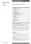
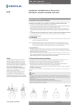
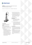
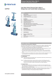
1
OPERATOR SERVICE MANUAL
POSITECH CORPORATION
191 N RUSH LAKE ROAD
LAURENS, IA 50554
Phone Number: 800-831-6026
24 Hour Service Phone Number: 541-954-2948
Email: [email protected]
SERIAL NO: _________
RUN NO: _________
Models Covered:
ReactionArm 1000LE
LodeArm 3030LE
LodeArm 4500LE
REV C
26-OCT-15
191 N. Rush Lake Road, Laurens, Iowa 50554 | T. 712.841.4548 | F. 712.841.4765 | www.positech.com
NOTES:
…………………………………………………………………………………………………………………………
…………………………………………………………………………………………………………………………
…………………………………………………………………………………………………………………………
…………………………………………………………………………………………………………………………
…………………………………………………………………………………………………………………………
…………………………………………………………………………………………………………………………
.…………………………………………………………………………………………………………………………
…………………………………………………………………………………………………………………………
…………………………………………………………………………………………………………………………
…………………………………………………………………………………………………………………………
…………………………………………………………………………………………………………………………
…………………………………………………………………………………………………………………………
…………………………………………………………………………………………………………………………
…………………………………………………………………………………………………………………………
…………………………………………………………………………………………………………………………
…………………………………………………………………………………………………………………………
…………………………………………………………………………………………………………………………
…………………………………………………………………………………………………………………………
…………………………………………………………………………………………………………………………
…………………………………………………………………………………………………………………………
…………………………………………………………………………………………………………………………
…………………………………………………………………………………………………………………………
…………………………………………………………………………………………………………………………
…………………………………………………………………………………………………………………………
…………………………………………………………………………………………………………………………
…………………………………………………………………………………………………………………………
Table of Contents
SECTION 1 - NAMING CONVENTION AND SERIAL TAG................................................................................... 1
A.
NAMING CONVENTION .............................................................................................................. 1
B.
SERIAL TAG LOCATION AND NOMENCLATURE ...................................................................... 2
SECTION 2 - SPECIFICATIONS .......................................................................................................................... 3
A.
MECHANICAL SPECIFICATIONS ............................................................................................... 3
B.
PNEUMATIC SPECIFICATIONS: ................................................................................................. 3
C.
HYDRAULIC SPECIFICATIONS .................................................................................................. 3
D.
ELECTRICAL SPECIFICATIONS................................................................................................. 3
E.
AERIAL NOISE ............................................................................................................................ 3
F.
ENVIRONMENTAL CONDITIONS ............................................................................................... 3
G.
PEDESTAL MOUNTING PATTERN ............................................................................................. 4
H.
OVERHEAD SPACER MOUNTING PATTERN ............................................................................ 4
I.
CONCRETE MOUNTING GUIDELINES....................................................................................... 5
J.
SOIL CONDITION: ....................................................................................................................... 5
K.
FULLY REINFORCED CONCRETE FLOOR CONDITION............................................................ 5
L.
POURED FOUNDATION CONDITION ......................................................................................... 5
M.
PLATING ON CONCRETE........................................................................................................... 5
SECTION 3 - INSTALLATION INSTRUCTIONS................................................................................................... 6
A.
PALLET INFORMATION .............................................................................................................. 6
B.
PEDESTAL INSTALLATION ........................................................................................................ 7
C.
SPACER INSTALLATION ............................................................................................................ 8
D.
LIFTING WITH A FORK TRUCK .................................................................................................. 9
E.
ATTACHING MANIPULATOR TO PEDESTAL ........................................................................... 10
F.
ATTACHING MANIPULATOR TO SPACER ............................................................................... 11
G.
PREPARING THE PRIMARY ARM FOR LEVELING .................................................................. 13
H.
LEVELING THE PRIMARY ARM – DRIFT METHOD.................................................................. 14
I.
PREPARING THE LIFT ARM FOR LEVELING ........................................................................... 15
J.
LEVELING THE LIFT ARMS ...................................................................................................... 16
K.
SETTING THE ROTATION STOPS ........................................................................................... 17
L.
BALANCE CONTROL ADJUSTMENTS ..................................................................................... 19
M.
METERING CONTROL ADJUSTMENTS ................................................................................... 20
SECTION 4 - MAINTENANCE, ADJUSTMENTS, & INSPECTIONS................................................................... 21
A.
AIR LINE SIZING FOR SUPPLY AIR ......................................................................................... 24
SECTION 5 - TROUBLESHOOTING .................................................................................................................. 25
APPENDIX A: MACHINE OPERATION PROCEDURE ..........................................................................................
APPENDIX B: DRAWINGS, SPARE PARTS LIST .................................................................................................
SECTION 1 - NAMING CONVENTION AND SERIAL
TAG
A. NAMING CONVENTION
Primary Arm
Main Post
Drag Brake
Middle Joint Brake
Adjustable Rotation Stop
(Option)
Lift Arm
Lift Cylinder
Pedestal (Option)
Main Post
Rotation Stop
(Option)
Middle Joint
End Joint
Down Shaft
Anchor Bolt
& Leveling Jacks
(Option)
1
B. SERIAL TAG LOCATION AND NOMENCLATURE
Model Number
Capacity of Base
Machine Only
Serial Number –
PROVIDE FOR SERVICE
SUPPORT
(shown on cover)
Weight of Tooling
Electrical
Voltage/Hertz/Phase
Electical Amps
Air PSI
Air SCFM
Design Category
Service Class
Serial Tag
Location
2
SECTION 2 - SPECIFICATIONS
A. MECHANICAL SPECIFICATIONS
See Profile Drawing for specification.
Equipment reach and load limit specifications are identified on the Profile Drawing supplied with specific
projects. This view will include application lift, and mounting configurations identified and supplied at time
of sale.
B. PNEUMATIC SPECIFICATIONS:
See Profile Drawing for specification.
C. HYDRAULIC SPECIFICATIONS
See Profile Drawing for specification.
D. ELECTRICAL SPECIFICATIONS
See Profile Drawing for specification.
E. AERIAL NOISE
Level of continuous acoustic pressure:
<80 dB (A scale)
Aerial noise measurements are taken at the operator’s work position and based on a 50th percentile
operator’s height.
See Profile Drawing for special notes.
F. ENVIRONMENTAL CONDITIONS
The manipulator is designed to operate inside a protected site from outside environmental conditions.
The operating environment needs be free of aggressive contaminants, acids, corrosive gases, salts, etc.
Operating Temperature:
50°F – 120°F [10°C – 49°C]
Relative Humidity:
<95%
See Profile Drawing for special notes.
3
G. PEDESTAL MOUNTING PATTERN
H. OVERHEAD SPACER MOUNTING PATTERN
4
I. CONCRETE MOUNTING GUIDELINES
It is solely the customer’s responsibility to provide the proper foundation for the manipulator and if
conditions are questionable or concrete does not look adequate the customer needs to consult a qualified
professional to inspect and make recommendations.
J. SOIL CONDITION:
The minimum soil condition that must also be achieved is 2500 lbs/sq ft [0.12 MPa].
K. FULLY REINFORCED CONCRETE FLOOR CONDITION
• 6 in [152mm] thick
• 3500 psi [24.1 MPa] compressive strength
• No cracks within 48in [1.2m] radius of pedestal
L. POURED FOUNDATION CONDITION
Foundation dimensions: 66”
X 66” X 18”
M. PLATING ON CONCRETE
Contact Positech for drawings or ordering information.
5
SECTION 3 - INSTALLATION INSTRUCTIONS
A. PALLET INFORMATION
Inspect manipulator for any signs of damage due to shipping. Document damage and make any claims to
the carrier.
MANIPULATOR AS SHIPPED FROM POSITECH:
Do not cut manipulator banding.
Refer to LIFTING WITH A FORK
TRUCK for installation instructions.
Shipping pallet
Fork truck pockets
6
B. PEDESTAL INSTALLATION
LEVEL PEDESTAL BEFORE INSTALLING MANIPULATOR ON PEDESTAL (See LEVELING THE
PRIMARY ARM for leveling the manipulator if it is already installed on pedestal.)
Refer to CONCRETE MOUNTING GUIDELINES for concrete guidelines before mounting pedestal.
Review profile drawing for torque requirement.
1. Set pedestal over area
and drill holes using
pedestal for template.
Locate pedestal so airline
can be routed through air
supply hole.
8. Torque the anchors.
2. Move pedestal and clean
holes with compressed air and
nylon brush.
3. Add 1 flat washer
between concrete and
pedestal for each jack.
4. Assemble anchor with
washer, lock washer, and
nut below anchor bolt
chamfer and drive in with
hammer.
7. Tighten the jam
nuts on jacks against
pedestal flange.
5. Torque anchor to seat
anchor. Then loosen.
6. Level pedestal by adjusting the
leveling jacks. Use a machinist’s
level to check in two directions
perpendicular to each other.
FINAL NOTES:
•
No grouting is required to mount this pedestal.
Re-torque this pedestal one week after install.
Re-torque pedestal according to suggested maintenance
schedule.
7
C. SPACER INSTALLATION
LEVEL SPACER BEFORE INSTALLING MANIPULATOR ON SPACER: (See LEVELING THE PRIMARY
ARM for leveling the manipulator if it is already installed on spacer.) Review profile drawing for torque
requirement.
1. Install jack
and jam nut.
2. Install flat
washer and lock
nuts if necessary.
6. Tighten the bolts.
3. Loosen the
jam nut for
leveling
7. Tighten the jam
nuts against spacer.
4. Loosen the
bolts enough to
level spacer.
8. Re-check
levelness of spacer
to make sure it is still
level
5. Level spacer
by adjusting the
leveling jacks.
Use a machinist’s
level to check in
two directions
perpendicular to
each other.
8
D. LIFTING WITH A FORK TRUCK
The manipulator is palleted to allow for easy installation with a fork truck. Raise the pallet above the
pedestal and lower the manipulator onto the pedestal and install as shown in ATTACHING
MANIPULATOR TO PEDESTAL
For overhead mount, simply raise the pallet up until the manipulator mates with the mounting surface.
See ATTACHING MANIPULATOR TO SPACER for installation details.
9
E. ATTACHING MANIPULATOR TO PEDESTAL
Lift manipulator as
shown in
LIFTING WITH A
FORK TRUCK.
10
Run air line through
hole in pedestal
and connect to
nipple.
Lower manipulator
until bearing housing
mates to pedestal.
Torque machine
mounting bolts. See
profile drawing.
F. ATTACHING MANIPULATOR TO SPACER
Lift manipulator until
bearing housing mates to
spacer
Run air line through
hole in spacer and
connect to nipple.
Lift manipulator as
shown in
11
Torque machine
mounting bolts. See
profile drawing.
LIFTING WITH A FORK
TRUCK
12
G. PREPARING THE PRIMARY ARM FOR LEVELING
All adjustments of the primary arm will be accomplished by adjusting the leveling jacks or shimming under
the primary bearing housing.
1. Position lift arm under primary arm. If lift arm will
not go under primary arm position lift arm straight out
from primary arm.
2. Loosen primary arm
brake caliper to allow
primary arm to rotate
freely.
13
H. LEVELING THE PRIMARY ARM – DRIFT METHOD
1. Select any of the four positions shown such as position A and rotate the primary arm into
that position. Release arm and step back so that any "drift" (movement to the left or the
right) of the primary arm can be noted.
2. To correct for drift, loosen the anchor bolts at the base and extend the levelling jacks on
the side of the pedestal base plate that the arm drifted toward.
3. Re-tighten anchor bolts and return arm back to position A and repeat steps 1 & 2, if drift
still occurs.
4. When all drift has been removed from position A, rotate primary arm 180 degrees to
position B and repeat steps 2 & 3.
5. When all drifts have been removed from position B, rotate primary arm 90 degrees to
position C and repeat steps 2 & 3.
6. When all drift has been removed from position C, rotate primary arm 180 degrees to
position D and repeat steps 2 & 3. This completes the levelling of the primary arm.
Position D
Position B
Position A
Position C
14
I. PREPARING THE LIFT ARM FOR LEVELING
Leveling adjustments to the lift arm do not affect the alignment of the primary arm.
1. Tighten primary caliper brake to
prevent primary arm from rotating.
.
3. Rotate lift arm parallel
to primary arm
2. Loosen middle joint brake caliper to
allow lift arms to rotate freely.
Leveling adjustments to the lift arm are performed by loosening or tightening the adjustment bolts in the
adjusting collar.
Adjustment bolts
Primary Bearing
Housing
Primary Arm
15
J. LEVELING THE LIFT ARMS
1.
2.
3.
4.
5.
6.
Select a position such as B and rotate the lift arm into that position. Release arm and
step back so that you can note any drift of the lift arm.
If any drift occurs, tighten the adjustment bolt or bolts, on the side that the arm drifted
towards, while at the same time loosening the adjustment bolt or bolts, on the side
opposite of the bolt or bolts being tightened.
Repeat steps 1 & 2 to check for any additional drift.
After all drift has been eliminated from position B, rotate lift arm 90 degrees to position C
and repeat steps 1, 2 & 3.
After all drift has been eliminated from position C, rotate lift arm 180 degrees to position
D and repeat steps 1, 2 & 3.
This completes the levelling of the lift arm. Re-adjust the primary arm brake (and middle
joint brake, if applicable) to fit your requirements.
Position D
Position A
Position C
16
K. SETTING THE ROTATION STOPS
Rotation stops may be supplied for the main post and middle joint rotation axis. Set the rotation stops to
allow the proper working range for the manipulator.
1.
2.
3.
4.
5.
6.
Rotate arm to stop position
Slide rotation stop onto brake disk with bumper located against caliper brake support
Tighten set screws to set stop location
Use 3/8 transfer punch to locate drill holes through center of the set screw
Drill ø0.266 holes thru brake disk
Tighten bolts, washers, and lock nuts
Main Post Rotation Stop
Middle Joint Rotation Stop
Shoulder bolt and washer
Set screw
Brake Disk
Slot
Lock Nut
17
The middle joint had holes pre-drilled to allow the lift arms to rotate equally in both directions. The rotation
stop can be moved to allow the lift arms to be stored under the primary arm.
If the middle joint rotation stop is moved, the lift arms may be able to contact the primary arm if the
operator moves the lift arms into the contact zone.
Use caution when relocating the middle joint rotation stop to keep the hoses routed around the middle
joint from being wrapped around the joint.
If two rotation stops are supplied for the middle joint, it may be useful to set one stop so the lift arm
cannot rotate past center. This is useful if the lift arms are used in one quadrant of rotation.
Lift Arm Rotation Direction
Second Rotation Stop
18
L. BALANCE CONTROL ADJUSTMENTS
See the pneumatic schematic for specific information regarding the pneumatic components used.
CONNECTING THE SUPPLY AIR
1.
2.
3.
Set the system pressure regulator to zero.
Connect supply air. Verify pressure and flow requirements listed on profile drawing.
Adjust system pressure regulator to requirement shown on profile drawing.
LOAD & NO LOAD BALANCE REGULATORS
If there is a bias circuit or a payload is lifted, there are two balance regulators. The regulators are labeled
accordingly.
1.
2.
Set the “No Load” balance regulator with the empty tool.
Set the “Load” or “Bias” balance regulator with the tool and payload or with the bias
switch actuated.
WARNING: The “Load” adjustment will need to be reset if the payload weight changes.
The “No Load” adjustment will need to be reset if the tool weight changes.
Use the following steps to set the “Load” and “No Load” balance regulators.
1.
2.
3.
4.
5.
Fully unscrew the “No Load” balance regulator.
With only the tool weight, carefully adjust the “No Load” regulator until the tool does not
drift up or down.
Fully unscrew the “Load” balance regulator.
Make sure the “Load” or “Bias” switch is activated.
Add the payload to the tool and carefully adjust the “Load” regulator until the tool and
payload does not drift up or down.
LOCK OUT PROCEDURE FOR BALANCE CONTROL
1.
2.
3.
Remove payload from tool and lower tool to lowest position.
Set the system pressure regulator to zero.
Lockout per factory procedure.
WARNING: The machine is not in a zero energy state. There may be pressure trapped in any
cylinder with a lock valve due to the lock valve minimum locking pressure. If a zero energy state
is required, cylinder lock valves need to be piloted by an external air source and some air lines
may need to be removed. See pneumatic schematic for more details and consult Positech with
additional questions.
19
M. METERING CONTROL ADJUSTMENTS
See the pneumatic schematic for specific information regarding the pneumatic components used.
CONNECTING THE SUPPLY AIR
1.
2.
3.
Set the system pressure regulator to zero.
Connect supply air. Verify pressure and flow requirements listed on profile drawing.
Adjust system pressure regulator to requirement shown on profile drawing.
LOCK OUT PROCEDURE FOR METERING CONTROL
1.
2.
3.
Remove payload from tool and lower tool to lowest position.
Set the system pressure regulator to zero.
Lockout per factory procedure.
WARNING: The machine is not in a zero energy state. There may be pressure trapped in any
cylinder with a lock valve due to the lock valve minimum locking pressure. If a zero energy state
is required, cylinder lock valves need to be piloted by an external air source and some air lines
may need to be removed. See pneumatic schematic for more details and consult Positech with
additional questions.
20
SECTION 4 - MAINTENANCE, ADJUSTMENTS, &
INSPECTIONS
Maintenance, adjustments, and inspections fall into three categories: every lift, frequent, and periodic.
•
Every lift evaluations: are visual examinations completed by operator before and during each lift.
•
Frequent evaluations: are visual examinations completed by the operator or designated persons
with records not required. The period to complete these evaluations is based on a service rating of
normal (monthly), heavy (weekly), or severe (daily) as explained below.
•
Periodic evaluations: are visual examinations completed by qualified personnel completing records
of apparent external condition to provide a basis for continuing evaluation. The period to maintain
these records is based on a service rating of normal (yearly), heavy (semiannually), or severe
(quarterly) as explained below.
Normal Rating
Heavy Rating
Severe Rating
Below 65% of rated load
65% to 100% of rated load
At 100% of rated load
Operate in an industrial
environment free of aggressive
contaminants
Life of manipulator is 2,000,000
cycles
Operate in an industrial
environment free of aggressive
contaminants
Life of manipulator is 1,000,000
cycles
Operate in abnormal environment
Life of manipulator is 500,000
cycles
For a manipulator that is outside these conditions refer to the profile drawing and/or consult the factory for
specific instructions.
EVERY LIFT EVALUATIONS
• Remove excess debris from surface of the load.
• Verify grip pad or vacuum cup is free of contaminant. Replace if excessively worn.
• Check the condition of the operator’s controls and gauges on controls
• Verify the load is secure after actuation of tooling and before moving the manipulator.
21
FREQUENT EVALUATIONS
• Move the manipulator in and out and around each axis and check for free motion. Check bearing
seals for leakage or damage. Replace any bearings that need to be replaced.
• Check friction devices, linkages, and other mechanical parts for excess wear and replace as needed.
Check drag brake pucks for excessive wear.
• Check welds on structural members for cracks. Look for cracked or missing paint over a weld. If
welds are torn from the base steel, cracked, or broken the manipulator should not be used until
repaired or determined safe. Consult factory for solution.
• Check structural members for deformations. Consult factory for solution.
• Check pivoting points and hook points for excessive wear and replace as needed.
• Replace missing guards, fasteners, covers, stops, decals, warning labels, or nameplates.
• Check for loose fasteners, especially set screws, and retighten.
• Check for leaks. Inspect condition and routing of all external hoses. Replace any leaky components
or cracked hoses.
• Operating the manipulator: Check that all functions are in adjustment, that all automatic mechanisms
functions properly, and that no functions interfere with current operation of the work cell.
PERIODIC EVALUATIONS
• Complete the frequent evaluations along with the following evaluations.
• Check anchor bolts and re-torque. See PEDESTAL INSTALLATION for detailed views.
• Check air supply to manipulator. See profile drawing for required pressure and flow.
• Check spacer mounting bolts if overhead mounted and re-torque. SPACER INSTALLATION for
detailed views.
• Check main post mounting bolts and re-torque. See
22
•
•
•
•
•
•
•
•
•
•
ATTACHING MANIPULATOR TO PEDESTAL for detailed views.
Check for worn or cracked gears, pulleys, sheaves, sprockets, bearings, chains, or belts and replace
as needed.
Check manipulator for level both in/out and around the main post and end joint. If the manipulator is
level, the manipulator will not wander or wander very little. See LEVELING THE PRIMARY ARM for
leveling the manipulator to eliminate drift in all operating quadrants.
Inspect lift cylinder pilot check valves. Inspect check valves on grip cylinder or vacuum check valves.
Check GSC adjustment. Use empty tool and adjust GSC knob until an audible pop is heard. Screw in
adjustment ¼ turn and tighten jam nut. Verify adjustment using a scrap part.
23
A. AIR LINE SIZING FOR SUPPLY AIR
Note: See profile drawing for required flow and pressure.
SCFM
Length of run in feet, Air line size in inches
FLOW
25
50
75
100
150
200
300
500
1000
6
½
½
½
½
½
½
½
¾
¾
18
½
½
½
¾
¾
¾
¾
1
1
30
¾
¾
¾
¾
1
1
1
1¼
1¼
45
¾
¾
1
1
1
1
1¼
1¼
1¼
60
¾
1
1
1
1¼
1¼
1¼
1½
1½
90
1
1
1¼
1¼
1¼
1¼
1½
1½
2
120
1
1¼
1¼
1¼
1½
1½
1½
2
2
150
1¼
1¼
1¼
1½
1½
2
2
2
2½
SLM
Length of run in meters, Air line size in mm
FLOW
7.5
15
25
30
45
60
90
150
300
150
13
13
13
13
13
13
13
19
19
500
13
13
13
19
19
19
19
25
25
580
19
19
19
19
25
25
25
32
32
1250
19
19
25
25
25
25
32
32
32
1700
19
25
25
25
32
32
32
38
38
2500
25
25
32
32
32
32
38
38
51
3400
25
32
32
32
38
38
38
51
51
4200
32
32
32
38
38
51
51
51
64
24
SECTION 5 - TROUBLESHOOTING
5. Grip release without being supported
A. Check GSC setting
B. If used, check 6 passage rotary
manifold for leaks
C. Verify proper hose connections
D. Check bleed down speed
6. Oil discovered on machine
A. Check lost load cylinder for
leaks
B. Check hydraulic lines to brakes
C. Verify FRL lubricator is not set
too high
D. Check FRL
7. Up/Down movement difficult
A. Check balance regulator
adjustment
B. Verify horizontal arms are not
rubbing on lift housing
C. Check lift cylinder and muffler
D. Check lost load cylinder
E. Check vertical cam eccentrics
F. Verify supply pressure and
sufficient flow
8. Rotation drift at tooling
A. Check main post level
B. Check anchor bolts on main
post
C. Check middle joint leveling
1. Machine does not move up or down
A. Check main air supply
B. Verify lost load cylinder isn’t
locked
C. Check main regulator
D. If used, check lift cylinder on/off
switch
E. Check pilot to lock valve
F. Check lock valve
2. Drifts up
A. Check metering valve for leaks
B. Check GSC valve for leaks
C. If used, check 6 passage rotary
manifold for leaks
D. Check balance setting
E. Check minimum lift setting
F. Check tool balance adjustment
setting
3. Drifts down
A. Check metering valve
B. If used, check 6 passage rotary
manifold for leaks
C. Check for leaky lift cylinder seal,
blocking valve connection
D. Check white poly lines for leaks
4. Main post rotation difficult
A. Check for main post bearing
wear
B. If used, check drag brake
adjustment
C. Check rails on trolley systems
25
APPENDIX A:
MACHINE
OPERATION
PROCEDURE
APPENDIX B:
DRAWINGS, SPARE
PARTS LIST