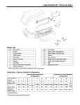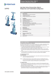
1
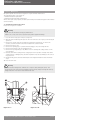
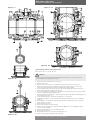
Ball valves side entry
Installation and Maintenance Instructions
FCT
Installation and Maintenance Instructions
Ball valves, trunnion mounted, side entry.
Section 1 - Valve Storage
1.1 Preparation and Preservation for Shipment
All valves are properly packed in order to protect the parts that are subject to deterioration during
transportation and storage on site. In particular, the following precautions should be taken:
1. The valves must be packed with the ball in the open position.
2. The weld ends surface shall be protected with suitable protective like Deoxaluminite. The end
shall be closed with plywood or plastic disc fixed at the edge by straps.
3. All actuated valves must be carefully securely palleted or crated, in order to ensure that the
parts of actuator (especially pneumatic piping or accessories) do not extend beyond the skid/
crate.
4. The type of packing must be defined in the Customer’s Order and shall be appropriate to ensure
safe transportation to final destination and eventual conservation before installation.
1.2 Handling Requirements
A - Packed Valves
Crates: Lifting and handling of the packed valves in crates will be carried out by a fork lift truck, by
means of the appropriate fork hitches.
Cases: The lifting of packed valves in cases should be carried out in the lifting points and at
the center of gravity position which have been marked. The transportation of all packed
material must be carried out safely and following the local safety regulations.
B - Unpacked Valves
1. The lifting and the handling of these valves has to be carried out by using appropriate means
and by respecting the carrying limits. The handling must be carried out on pallets, protecting the
machined surfaces to avoid any damage.
2. With valves of large dimensions, the sling and the hooking of the load must be carried out by
using the appropriate tools (brackets, hook, fasteners, ropes) and load balancing tools in order to
prevent them from falling or moving during the lifting and handling.
Caution
For valve handling and/or lifting, the lifting
equipment (fasteners, hooks, etc.) must be
sized and selected while taking into account
the valve weight indicated in the packing list
and/or delivery note. Lifting and handling must
be made only by qualified personnel.
Do not use the lifting points located on the
actuator, if any, to lift the valve. These lifting
points are for the actuator only.
Caution must be taken during the handling
to avoid that this equipment passes over
the workers or over any other place where a
possible fall could cause damage. In any case,
the local safety regulations must be respected.
1.3 Storage and Preservation before Installation
In case the valves have to be stored before installation, the storage has to be carried out in a
controlled way, and has to be performed in accordance with the following criteria:
1. The valves have to be stocked in a closed, clean and dry storage room.
2.The ball must be in the open position and the end faces must be protected with plastic or
wooden discs fixed with straps. If possible, keep the original protection.
3.Periodical checks have to be carried out in the storage area to verify that the above mentioned
conditions are maintained.
For actuated valves, in addition to the above please refer to the warnings in the relevant actuator
manual.
Note
Storage in an open area for a limited period can be considered only in case the valves have
appropriate packing (packed in cases lined with tarred paper, and contents well protected with
barrier sacks).
Do not place consignment packages directly on the ground.
Do not expose consignment packages to the weather or directly to the sun.
Check the packaging every two months.
Figure no. 1
www.pentair.com/valves
Pentair reserves the right to change the contents without notice
FCTLT-0002-EN-1307
Ball valves side entry
Installation and Maintenance Instructions
Section 2 - Installation
2.1 Preparation before installation
1. Carefully remove the valve from the shipping package (box or pallet) avoiding any damage to
the valve or, in case of automated valves, to the electric or pneumatic/hydraulic actuator or
instrumentation.
2.Clean the inside of the valve using an air line. Ensure that there are no solid objects such as
pieces of wood, plastic or packing materials within the valve or on the valve seat.
3.Confirm that the materials of construction listed on the valve nameplates (service and
temperature) are appropriate for the service intended and are as specified.
4.Define the preferred mounting orientation with respect to the system pressure. If any (see arrow
on the body), identify the upstream side (high pressure) and downstream side (low pressure).
Warning
• Verify that the direction of the flow in the line corresponds to the arrow indicated on the
valve body. Valves without the arrow are bi-directional.
• See the actuator user manual for the actuator preparation.
• Verify the assembly of the overpressure relief device in case of liquid service and double
piston effect option.
2.2 Installation Instructions
Ball valves are normally installed in horizontal pipe with vertical stem.
These valves can also be installed with no limitation regarding the pipe or stem orientation.
However, in this case the actual pipe/stem orientation should be advised to allow for the right
position of the drain plug.
Unless otherwise recommended by the manufacturing plant, the valve should be installed with
the ball in the open position, to ensure that the seat rings are not damaged during installation.
Particular care should be taken with those valves equipped with ‘fail-close’ actuators.
For operating temperatures above 200°C (392°F) thermal insulation of the valve body is
recommended.
Handling and lifting of the valves during installation MUST be performed following the same criteria
and instructions described in previous points “1.2 Handling Requirements” and “1.3 Storage and
Preservation before Installation”.
Buttweld Valves
Position the valve and check the alignment with the pipe.
Proceed with welding, in accordance with the applicable welding procedure.
Important
It is recommended to perform piping flushing before installation of the valve. If this is not
possible, the valve must be set with the ball in full open position before starting with flushing.
For buttweld end valves:
To avoid any damage to the gaskets, the temperature during the pipe welding and the heat
treatment has to be monitored by a thermocouple placed in the seat grease injector holes.
Make sure to limit the temperature at maximum of 200°C.
This instruction has to be carefully followed especially in case there are not any transition piece
(pup piece) welded to the valve.
The use of a transition piece shall be prescribed, in case the welded pipe strength is greater
1,5 times the valve strength.
2.3 Valve Verification Before Start Up
1. Verify the tightness of the drain plug and of the vent valve. Since all gaskets are self-energized,
tighten the bolts enough to assure the contact between the surfaces and to avoid any nuts
disassembly, which may be caused by possible line vibrations. There is no need to overtighten
the bolts to assure gasket tightness.
2.Check the valve operability by stroking it to “full open” and “full close”.
Important
If piping system is pressurized with water for testing, and in case the piping system has been
shut down after testing for a long time, the following recommendations should be adopted:
a.Use corrosion inhibitor with water to pressurize the piping system
b.After testing, the piping system should be depressurized and the test water completely
drained.
Pentair reserves the right to change the contents without notice
page 2
Ball valves side entry
Installation and Maintenance Instructions
2.4 Operations Instructions
1. Split Body Ball Valves do not require special care to work properly. The following instructions will
help provide a satisfactory and long life service.
2.Make sure to perform periodic valve verification as described in paragraph 2.5.
3.In case of actuated valves always follow the specific instructions given by the actuator’s
manufacturer.
4.Never change the setting of torque and/or limit switches which have been carefully set during
the final test at our workshop.
5.Never change the setting of the mechanical stops of the gearbox.
2.5 Periodic Valve Verification During Service
A - Normal Check
1. Verify monthly that there is no leakage from the gaskets or through the seats. If the leakage
has been detected in the stem/bonnet area, inject the proper seal as it grease through the stem
grease injector. Use the seat injectors device to stop the leakage of the valve in close position.
The sealant injection is to be considered as an emergency operation to stop the leakage up to the
next planned maintenance job. If the leakage does not stop, follow the maintenance procedure
for the replacement of the gaskets in Section 3.
2.For actuated valves, in addition to the above, please refer also to the warnings in the actuator
manual.
Important
Do not overtighten the bolts to assure gasket tightness. The gaskets are self-energized.
B - Preventive Actions
1. Every 3 months verify the tightness of bolts, drain, vent.
2.Every 5 years disassemble the critical service valves and/or actuated valves, verifying the sealing
surface and lapping them again if necessary. Change all the gaskets.
3.For the actuator, proceed as indicated in its maintenance manual.
2.6 Troubleshooting Guide
Symptom
Possible Cause
Solution
Stem gasket leaking
1. Gasket damage
1. Sealant injection (temporary)
2.Gasket replacement (see section 3)
Body-closure leaking
1. Gasket damage
1. Gasket replacement (see section 3)
Body-bonnet gasket
leaking
1. Gasket damage
1. Gasket replacement (see section 3)
Valve leaking
1. Valve not fully closed
2.Debris trapped in valve
3.Sealing surface damaged
1. Close the valve
2.Cycle and flush (with valve open) to
remove debris
3.Temporarily perform sealant
injection. As a further operation,
recondition the sealing surface (this
operation has to be performed by
Mfg. plant or nominated service
company only).
Jerky operation
1. Not enough feed pressure
1. Increase the actuator feed pressure.
Pentair reserves the right to change the contents without notice
page 3
Ball valves side entry
Installation and Maintenance Instructions
Section 3 - Maintenance
Our split body ball valves have been designed to require minimum maintenance.
This manual describes on site repairs as:
- Stem/Bonnet Gasket replacement
- Full Gasket/Trunnion Bearings replacement.
All the other repairs (major repairs) should be performed by the manufacturing plant or Nominated
Service Company.
3.1. Stem/Bonnet Gasket Replacement
Please refer to figures no 2 and 2A
Warning
Depressurize the line before starting any maintenance.
Failure to do so may cause serious personal injury and/or equipment damage.
1. Place the valve in fully open or fully closed position.
2. Open the vent and discharge the pressure. The vent valve has to be in open position during all
operations.
3. Remove the operator from the top flange unscrewing the relevant bolts. To remove the
actuator, follow the relevant instructions included in the actuator manual.
4. Remove the key (pos 115)
5. Remove the top flange (pos 11) and the thrust bearing (pos 121) unscrewing the nuts.
6. Remove the bonnet (pos 12) unscrewings the nuts.
7. Remove the lip seal gasket (pos 13b). Make sure not to damage the sealing surfaces on the
stem and body.
8. Carefully clean all the sealing surfaces using proper remover products. Visually check all the
sealing surfaces: if damaged, they should be repaired. For lip-seal assembling use the conical
ring special tool.
9. Change all the gaskets and reassemble all parts following backwards the above mentioned
steps.
10. Close the vent valve.
Warning
The stem has been designed as ‘antiblow out’ to improve safety during the service. This
means that the stem cannot be disassembled from the valve by simply removing the valve top
flange and bonnet. You need to disassemble all the valve.
Figure no. 2
Figure no. 2A
Pentair reserves the right to change the contents without notice
page 4
Ball valves side entry
Installation and Maintenance Instructions
Figure no. 3
Figure no. 3A
2
9
7a
7
12 11 115
109
86
4a
13b
121
6
5
1
4a
4
4a
44
2
Figure no. 3B
3.2 Full Gasket/Trunnion Bearings Replacement
Please refer to fig. no. 3, 3A, 3B, 3C, 3D.
Warning
Figure no. 3C
Depressurize the line before starting any maintenance. Failure to do so may cause serious
personal injury and/or damage to the valve.
1.
2.
3.
4
5.
6.
7.
8.
9.
10.
11.
12.
13.
Figure no. 3D
14.
15.
16.
17.
Remove the valve from the line (see Section 4).
Open the vent valve.
Close the valve. The valve has to be maintained in closed position (see also point 5).
Remove the operator from the top flange unscrewing the relevant bolts. To remove the
actuator follow the relevant instructions included in the actuator manual.
In case of ESDV with a fail-open actuator ask the manufacturing plant specific instructions
before disassembling the actuator from the valve.
Place the valve with the end flange (pos 2) on the floor and horizontal stem (see fig. 3A). Make
sure not to damage the flange sealing surface.
Remove the upper valve lifting (pos. 157), the support leg (pos. 164) and the end flange (pos. 2)
unscrewing the nuts (pos. 9).
Lift the upper flange (pos. 2) end from the body (pos. 1). See fig. 3B.
Verify that the ball (pos. 5) is in closed position and that the bonnet (pos. 12) is assembled to
the body.
Lift the ball (pos. 5) and the ball trunnion plates (86) from the body. Remove the “antistatic
device springs”. See fig. 3C.
Remove the key (pos 115).
Remove the stem (pos. 6) from the body.
Remove the lip seal gasket (pos 13B) from the body. Make sure not to damage the sealing
surface on stem and body.
Remove the top flange (pos. 11) unscrewing the nuts.
Remove bonnet (pos. 12).
Disassemble the seat (pos. 4) from the end flange (pos. 2).
Remove all the gaskets springs and thrust bearings.
Pentair reserves the right to change the contents without notice
page 5
Ball valves side entry
Installation and Maintenance Instructions
18. Carefully clean all the sealing surfaces by using proper removing products. Visually check all
the sealing surface. If they are damaged they should be repaired. The sealing surface repair
job has to be performed under direct supervision of manufacturing company or nominated
qualified company only.
19. Change all the gaskets and bearings.
20. Reassemble the topwork of the valve in this sequence: stem, bonnet and top flange. For the
bonnet follow the instructions at point 3.1. Make sure to lubricate all the relevant surfaces with
suitable grease.
Make sure to rotate the stem in the right position in order to allow the ball assembly.
21. Assembly the new seat gaskets (pos. 4a, 4b, 4c) on the seat.
22. Put the springs (pos. 44) in the end flanges holes.
23. Assemble the seat ring to the end flange.
24. After having changed the thrust bearings (pos. 109), assemble the trunnion plate (pos. 86) to
the ball (pos. 5).
25. Let down the assembled ball plus trunnion plates (see fig. 3D) in the valve body. Make sure
to put the stem in the slot placed on the top of the ball trunnion. Remember to place the two
antistatic springs between the stem and the bottom surface of the slot.
26. Make sure the ball is in closed position. Assemble the end flange with the seat ring to the
body. Put the valve lifting (pos. 157) and support leg (pos. 164). Remember to position the fire
safe gasket (pos. 7a) in the body grove and screw the nuts (pos. 9).
27. Rotate the valve and place with the other flange end on the floor with horizontal stem
(see fig. 3A).
28. Repeat the instructions: 7, 8, 9, 16, 17, 18, 19, 21, 22, 23, 26.
29. Rotate the valve and place it on its feet.
30. Reassemble the valve operator.
31. Close the vent valve.
Section 4 - Valve Removal
If the valve needs to be removed from the line for some extraordinary reason, the user should
ensure the following:
Warning
Depressurize the line before starting any maintenance. Failure to do so may cause serious
personal injury and/or damage to the valve.
1. The valve is depressurised;
2. The pipe shall be cut as far away from the valve as possible.
Section 5 - Greases and Special Tools
5.1 Sealant Greases
The suggested sealant grease is MOLYCOTE 111, valve lubricating and sealing silicone compound
by DOW CORNING.
5.2 Special Tools
The only tool required is the conical ring suitable for the gasket assembly (pos. 133). See fig. 2A.
Pentair reserves the right to change the contents without notice
page 6