1
21 sedling Road
Wear East ndustrial Estate
Washington
Tyne& Wear NE38 9BZ UK
Thermocouple
Equipment
Technologies Limited
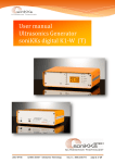
Ultrasonic Generator
Sonic Digital Series USG - SD
Service Manual
The Copyright is the property of TET Limited
This document is supplied by TET Limited on the condition that it may not be copied or
disclosed to others except for distribution as directed by or as authorised in writing by
TET Limited
Thermocouple Equipment Technologies Limited
Contents
Page
1.
Introduction …………………………………………………………………… 2
1.1
Safety instructions …………………………………………………………… 2
1.2
Warranty ………………………………………………………………………. 3
1.3
Power supply …………………………………………………………………. 3
1.3.1
Operating and display elements ……………………………………………. 3
1.4
The LCD display ………………………………………………………………. 4 & 5
1.5
Functions in the Settings menu ……………………………………………… 6
1.6
Error messages and trouble shooting ……………………………………… 7
1.7
Connections on the back panel of the generator ………………………….. 8 & 9
1.8
Interface ……………………………………………………………………….. 10 & 11
1.9
Care and maintenance ……………………………………………………….. 12
1.10
Specifications …………………………………………………………………. 12
1.13
CE conformity …………………………………………………………………. 12
Service Manuals
Generator USG-SD
Page 2 of 13
Thermocouple Equipment Technologies Limited
Introduction
Dear customer,
You have purchased a high-quality product, which has been developed using cutting edge
technology.
Please read the manual carefully before using the product to avoid any problems or
malfunctions.
The "USG - SD" ultrasonic generators are intended solely for the following use:
Connection and operation of ultrasonic converters supplied by TET Limited.
Safety instructions
For your own safety and the operational safety of the device, please read the following
instructions carefully prior to using your device for the first time.
Always observe all warnings and instructions on the device itself.
Always disconnect the device from the mains power prior to cleaning or mounting/removing a
part. Do not use liquid cleaner or cleaning sprays. Use only a damp cloth.
Never operate the device in areas where there is a risk of water penetration.
The device should be positioned on a sufficiently stable surface as it may be severely damaged
by vibration or dropping.
It is essential to use only the power supply values stated on the device.
With the exception of the steps listed in the manual, you should never attempt to repair the
device yourself.
In the following cases the device should be disconnected from the mains power and passed to
a trained service technician:
If
If
If
If
the mains cable or plug is damaged
water or any other liquid has penetrated the device
the device has been dropped or the housing is damaged
the functions of the device clearly deviate from standard operation
ATTENTION: The device may only be opened by trained experts.
Service Manuals
Generator USG-SD
Page 3 of 13
Thermocouple Equipment Technologies Limited
Warranty
The scope and duration of the warranty are contained in the terms of delivery or sales contract.
The version in effect at the time of purchase prevails.
No warranty is given for the following cases:
Damage due to improper operation.
Use other than that intended.
Improper changes or alterations performed without prior approval of the manufacturer.
Damage caused by extreme factors such as impact shock, dropping, moisture and dirt.
Insufficiently qualified operating staff.
Non-compliance with the valid safety and accident prevention regulations.
Power supply
The ultrasonic generator is powered via the accompanying cooling device connection cable
with AC 230V / 50 / 60Hz.
The device has an internal fuse (10AF).
ATTENTION: Switch to voltage-free or pull out the mains plug prior to replacing a fuse.
Only replace fuses of the same type.
Only to be carried out by trained staff.
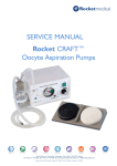
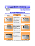
Operating and display elements on the front panel
LED - HF:
Lights up when the generator supplies HP voltage.
LED - <>Nominal:
Displays "Out of window" when time-out circuit or power monitor is set.
LED - Mode:
Displays selected special functions, such as timer function, time-out
circuit or energy function.
LED - Error:
Lights up in the event of an error.
LEDs - Power bar
Graph (10 -100%):
Displays the output power supplied in increments of 10%.
Encoder / Select:
For setting and entering values.
Test button:
Pressing this button switches on the generator.
See the Settings menu for configuring the Test button.
Service Manuals
Generator USG-SD
Page 4 of 13
Thermocouple Equipment Technologies Limited
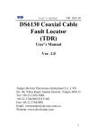
The LCD
The LCD comprises various displays and functions:
I.)
Power display in "Watt":
Indicates the power output currently being supplied. After switching off, the maximum power
supplied remains saved until the next time the device is switched on.
2.)
Working frequency display
This menu item shows the current working frequency of the generator.
3.)
Amplitude setting:
Use the "Select" encoder to set the desired output amplitude between 50 and 100% of the
nominal generator amplitude.
The amplitude is set by pressing the encoder. Turn to set the desired amplitude. Press once
more to accept the amplitude setting.
4.)
Timer function "Single Run" and "ON/OFF" operation:
Pressing the encoder can set a time of up to ten seconds.
This time elapses when the generator is switched on via the interface or the test button. After
the time has expired, no error message is generated. When switching on the generator via the
test button, the "TIMEOUT" error message is displayed after the time has expired.
The end of the expired time can be determined by calling up the "HF - DA" signal via the
interface.
If an "OFF" time is set, the generator is continuously switched on and off (intermittent mode)
5.)
Energy function
This is the energy-setting mode. The generator switches off automatically when the preselected energy level has been reached. The time required to reach this energy level is also
displayed.
6.)
Time-out circuit
A time window may be defined by setting a minimum and maximum time. This is a monitoring
function. If during the next cycle the time set is exceeded or not reached, this is indicated by the
LED " Aux 1" -"out of window".
Service Manuals
Generator USG-SD
Page 5 of 13
Thermocouple Equipment Technologies Limited
7.)
Setting the starting frequency:
The generator has an automatic "frequency tuning function". This means that it sets itself fully
automatically to the resonant frequency of the connected transducer system. The capture range
is 1 kHz. It is necessary to know the resonant frequency of the connected system. A starting
frequency approximately 500 Hz above the resonant frequency of the connected system
generally provides good results. In special cases, however, it may also be necessary to set the
starting frequency nearer to the resonant frequency of the transducer system.
Do not under any circumstances set the starting frequency lower than the resonant frequency
of the connected transducer system!
Pressing and turning the encoder can alter the starting frequency. The range depends on the
type of device.
On generators with a frequency range of 40 kHz this range is 4 kHz.
For 20 kHz, 35 kHz and 36 kHz generators the range is approximately 1 kHz.
8.)
"Power window" function
It is possible to define a "power window".
"LOW" = lower value
"HIGH" = upper value
If the power output is outside the defined window during a switch-on period, this is indicated by
the LED " AUX1 " lighting up on the front panel. In addition, any voltage on PIN 5/9 (signal
name: "HF-DA-ERROR") of the interface is switched through to Pin 11 (signal name:
"Window").
9.)
Contrast setting:
Press and turn the encoder to alter the contrast on the LCD. Press again to accept the value
set.
Set the contrast so that the LCD can be read easily.
10.)
LED background lighting:
Press and turn the encoder to switch the background lighting of the LCD on and off.
We recommend switching on the background lighting to ensure that the display can be read
clearly.
11.)
Settings
Enter the password "6354" to open the Settings menu.
This is done by pressing and turning the encoder.
When the correct password is set, confirm it by pressing the encoder.
Service Manuals
Generator USG-SD
Page 6 of 13
Thermocouple Equipment Technologies Limited
Functions in the Settings menu
I.)
I/0 POLARITIES
Remote IN:
Factory setting:
Letter "H":
Letter "L":
By changing this value you can alter the polarity of the remote input.
Closed contact switches on the generator.
The generator is switched on with closed contact.
The generator is switched on with open contact.
Error out:
By changing this value you can switch over the polarity of the internal
error relay. Factory default setting: Closed contact means error.
If the polarity is changed so that an open contact signals an error, please
note that the contact is closed when there is no mains power on the
generator or when the generator indicates a complete failure.
Keeping the factory setting "L" means that the above mentioned errors
will be recognized.
Closed contact means error.
Open contact means error.
Recommendation:
Letter "L":
Letter "H":
RF detect:
Altering this value changes the HF-DA status signal (generator supplies
HF voltage).
Letter "H":
Letter "L":
Closed contact - generator supplies HF.
Open contact - generator supplies HF.
Please observe that this contact is open when there is no mains power or when the generator
indicates complete failure.
Recommendation:
4.)
Keep the factory setting "L".
TEST BUTTON
There are three possible configurations for the Test button on the front panel:
a.) PUSH - the generator is switched on by pressing the Test button and switched off when the
button is released.
b.) TOGGLE - the generator is switched on by pressing the Test button and it remains switched
on when the button is released. Press the button again to switch off the generator.
c.) DISABLED - test button is disabled
5.)
Operating hours display
This displays the time during which the generator outputs HF.
Display format: minutes, hours, days.
Service Manuals
Generator USG-SD
Page 7 of 13
Thermocouple Equipment Technologies Limited
6.)
EXIT - to exit the Settings menu
Error messages and trouble shooting
The following error messages can appear on the display:
E- SEARCH: Frequency not found
The generator cannot find the working frequency.
Possible causes:
No transducer system is connected.
The transducer system is defective.
Supply line or plug defective.
Remedy:
Replace the transducer, booster or sonotrode.
Check the supply lead and plug connection.
A - PROTECTION ACTIVE:
The electronic over current cut-out has identified an error.
Possible causes:
Transducer, booster or sonotrode defective.
Supply lead or plug defective.
Remedy:
Unscrew the converter plug on the housing.
Switch on the generator without the transducer system connected
a.) Error message continues to show: the generator is defective.
b.) Error message does no longer show: Check the transducer, booster,
sonotrode and supply lead.
NO RF - DETECTED:
The electronic overload/short-circuit cut-out has identified an error.
Causes and remedy: see A -PROTECTION ACTIVE
OVER TEMPERATURE:
The generator is too hot.
Possible causes:
The ventilation slits of the generator are blocked.
The generator is located in an unsuitable position.
The transducer, sonotrode or booster is defective.
The fan is defective.
Remedy:
Check the fans! The fan must start up briefly when the mains power is
switched on.
Check the air inlet / outlet of the generator.
Check the transducer.
Service Manuals
Generator USG-SD
Page 8 of 13
Thermocouple Equipment Technologies Limited
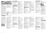
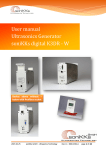
Connection on the back panel of the generator
HF – Connection Port – Pin
Version with “Lemosa Socket”:
Transducer minus connection:
All connection that are arranged in a semicircle
(connected internally).
Transducer plus connection:
Individually insulated connection.
ATTENTION:
The transducer may only be operated with the special connection cable supplied by TET
Limited!
Service Manuals
Generator USG-SD
Page 9 of 13
Thermocouple Equipment Technologies Limited
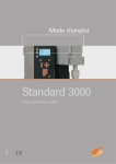
Version with BNC connection:
Transducer minus connection:
Transducer plus connection:
Screen of the BNC socket.
Inner conductor of the BNC socket.
Only use the special connection cable supplied by TET Limited to connect the transducer!
ATTENTION:
When connecting the converter via a BNC cable, a secure PE conductor connection must also
be established between the generator and converter using a cable of sufficient diameter
(minimum 1.5mm).
There is a PE terminal on the back panel of the generator for connecting this PE conductor.
Mains connection socket with on-off switch:
ATTENTION:
Only use the mains lead supplied or an approved mains cable
(conforming to the appropriate standards) with PE conductor to connect
the generator.
Connection: 230 Volt /SA.
Assignment of the 15-pole interface port
PIN No. on DSUB
Port Interface X1
Signal name
Description
1
.+15 VOLT OUT
15 Volt for external use
2
P OUT
Output 0 - 10 Volt = Output pow er 0 - 100%
3
A-EXT.-IN
Input 5 - 10 Volt for amplitude control
4, 8, 10 & 15
GND
Common reference point = Ground
5&9
HF-D-ERROR
Common relay connector for "HF-DA" and Error
6
HF-DA
Relay output "HF-DA
7
ERROR
Relay output "ERROR"
8, 4, 10 & 15
GND
Common reference point = Ground
5&9
HF-DA-ERROR
Common relay connector for "HF-DA" and Error
10, 8, 4 & 15
GND
Common reference point = Ground
11
WINDOW
Output "Window "
12
FAN-ON
Monitor output = 12 Volt w hen the fan is running
13
FS-24V
Remote control input 15 - 24 Volt
14
FS - GND
Remote control nput (Gen = input w ith connection to GND)
15, 4, 8 & 10
GND
Common reference point = Ground
Service Manuals
Generator USG-SD
Page 10 of 13
Thermocouple Equipment Technologies Limited
INTERFACE DESCRIPTION
1.)
Signal"+ 15 Volt Out"
DSUB PIN 1
At this output, the voltage available is 15 volts. This voltage can be loaded with a
maximum of 100 mA and can, for example, be used to output a voltage for the HF-DA
and/or "Error" function.
This voltage can also be used to switch on the generator at the "Input FS-24V".
2.)
Signal "POUT"
DSUB PIN 2
At this output a power-proportional voltage between 0 and 10V (= 0- 100% output
power) is available. Reference point = GND.
3.)
Signal "AN-EXT. -IN"
DSUB PIN 3
Applying a voltage of between 5V and 10V allows the amplitude of the generator to be
set between 50% and 100% of the nominal amplitude. To activate this function the
"external voltage" setting under the "Pwr.src" menu item in the setting menu (password
6354) must be selected. Reference point is "GND".
4.)
Signal "HF-DA ERROR"
DSUB PIN 5/9
Shared input/output for the internal relays "HF-DA" and "ERROR".
5.)
Signal "HF-DA"
DSUB PIN 6
If the ultrasonic generator is switched on via one of the signals "FS-24V", "FS-GND" or
using the test button on the front panel and supplies HF voltage, (i.e. there is also no
malfunction present), an internal floating relay contact is made (between PIN 6 and PIN
5/9). The "root" of this relay contact is brought out at Pins 5 and 9 (these pins are
connected internally) of the DSUB socket.
This relay contact can only be scanned by an external control system.
It is, of course, also possible to switch through a voltage applied to Pin 5 or 9
(max.24V/100mA).
Scanning of this contact is particularly useful if a timer operation is performed and the
generator automatically switches off after the time span has elapsed.
The contact can also be switched to reverse polarity in the setting menu. The "I/O
polarities -RF detect" menu item. Factory defauJt setting: Contact closed when the
generator is outputting HF voltage.
6.)
Signal "Error"
DSUB PIN 7
This is the output of an internal relay (root at pin 5 or 9). This relay signals malfunctions
of the generator. This means that if the generator is switched on and, for whatever
reason, does not supply the specified output power, this relay will be activated. Factory
default setting: Closed in the event of an error. The polarity may be changed in the
setting menu under the "I/O Polarities" menu item ("Error detect").
Of course it is also possible to switch through a voltage externally applied to "Error-com"
(max. 24V/100mA).
Service Manuals
Generator USG-SD
Page 11 of 13
Thermocouple Equipment Technologies Limited
7.)
Signal "Window"
DSUB PIN 11
As described, a warning message is issued when the "Power-window" or, "Timewindow" function is activated. In this case the LED " AUX" lights up on the front panel.
8.)
Signal "FAN -ON"
DSUB PIN 12
When the internal fan is running, a control voltage of 12 Volt is available at this output to
monitor the function of the fan.
9.)
Signal "FS-24 Volt" DSUB PIN 13
Switches on the generator (ultrasound on) by applying a voltage of 15 to 24 Volt
between PIN 13 and GND (PIN 4/8/10/15)
10.)
Signal "FS-GND"
DSUB PIN 14
Switches on the generator (ultrasound on) with a relay contact or switch by connecting
PIN 14 on the DSUB socket to GND (PIN 4/8/10/15).
11.)
Signal "GND"
DSUB PIN 4,8,10,15
The GND signal is available on several pins of the DSUB socket.
It is the common reference point for all input/output signals.
Service Manuals
Generator USG-SD
Page 12 of 13
Thermocouple Equipment Technologies Limited
Care and maintenance
The ultrasonic generator does not require any special care or maintenance.
Remove dust and dirt with a damp cloth at regular intervals.
ATTENTION: Do not use any aggressive cleaning agents.
Specifications
Connection
Voltage
230 Volt 50/60
USG 440 SD
Hz
230 Volt 50/60
USG 436 SD
Hz
230 Volt 50/60
USG 840 SD
Hz
230 Volt 50/60
USG 835 SD
Hz
230 Volt 50/60
USG 1030 SD
Hz
230 Volt 50/60
USG 1520 SD
Hz
230 Volt 50/60
USG 2020 SD
Hz
Model
Power
Consumption
Connected
Load
Ultrasound
Frequency
3 Amp
660 VA
40 kHz
3 Amp
660 VA
36 kHz
4 Amp
950 VA
40 kHz
4 Amp
950 VA
35 kHz
5 Amp
1200 VA
30 kHz
7 Amp
1440 VA
20 kHz
10 Amp
2200 VA
20 kHz
Output
Voltage
Approx 600
Volt
Approx 600
Volt
Approx 600
Volt
Approx 600
Volt
Approx 600
Volt
Approx 600
Volt
Approx 600
Volt
Output Power
400 Watt max
400 Watt max
800 Watt max
800 Watt max
1000 Watt max
1500 Watt max
2000 Watt max
Declaration of CE conformity
We: (TET Limited):
Hereby declare that the product Designation:
"Digital Sonic USG- SD" ultrasonic generator
Conforms to the requirements of the following EMC standards
EN 50081-1, EN 50082-2,EN 55022, EN 55014, EN 60555, EN 61000
It also meets the requirements of the Low Voltage Directive.
Service Manuals
Generator USG-SD
Page 13 of 13