1
No.1606-IS
Rev H
1-14
A Division of Thiessen Products, Inc.
INSTRUCTION SHEET FOR JIMS® FORGED PISTON SETS
Recommended Tools
Part No.
JIMS® No. 1235
JIMS® No. 1236
JIMS® No. 930
Description
Piston Ring Expander
Piston Ring Compressor
Cylinder Torque Plates
Read instruction sheet completely before performing work. Also read H-D Service Manual for
piston and cylinder repairs.
JIMS® Twin Cam Piston sets are CNC milled from aerospace forged 2618 aluminum alloy. Pistons are
available in Big bore sizes and Stroker sizes of STD to +.010”.
For .927” wrist pin clips use JIMS® 4-pack, No. 1604K
For .827” wrist pin clips use JIMS® 4-pack, No. 1602K
Alpha & Beta, Series II Twin Cam 100”
Big Bore Piston Sets H-D Stock Stroke Flywheels
Part No.
Application
Bore Size
No. 1603
Use on Twin Cam 100” 1999-Present
*Using a .040” thick head gasket.
Stroke Application
Compression Ratio**
Rings
4”
*9.56:1
No.1491
4” STD
**Compression Ratio Approximate. 0.927” Wrist pin O.D.
Alpha & Beta, Twin Cam 106” Stroker Piston Sets (JIMS Stroker Kits)
Part No.
Application
Bore Size Stroke Application Compression Ratio**
No. 1614
Use on Twin Cam 106” 1999-2006
4.125”
4”
*10:1
Rings
No.1286-1354
**Compression Ratio Approximate. 0.927” Wrist pin O.D.
*Using a .040” thick head gasket.
Alpha Twin Cam 110” Stroker Piston Sets (JIMS Stroker Kits)
Part No.
Application
Bore Size Stroke Application Compression Ratio**
No. 1615
Use on Twin Cam 110” 2007-Present
4” STD
4.375”
*10:1
Rings
No.1491
**Compression Ratio Approximate. 0.927” Wrist pin O.D.
*Using a .040” thick head gasket.
Alpha & Beta, Series II Twin Cam 113”
Stroker Piston Sets (JIMS Stroker Kits)
Part No.
Application
Bore Size
No. 1607
Use on Series II Twin Cam 113” 1999-Present 4” STD
No. 1607B
Use on Series II Twin Cam 113” 1999-Present 4” +.010
*Using a .040” thick head gasket.
Stroke Application
Compression Ratio**
Rings
4.5” / 4.625”
*10.19:1
No.1491
4.5” / 4.625”
*10.19:1
No.1493
**Compression Ratio Approximate. 0.927” Wrist pin O.D.
Alpha & Beta, Series I Twin Cam 113” & 116”
Stroker Piston Sets (JIMS Stroker Kits)
Part No.
Application
Bore Size Stroke Application Compression Ratio**
No. 1620
Use on Series I Twin Cam 113” & 116” 1999-Present
4” + .005”
*Using a .040” thick head gasket.
4.5” / 4.625”
*9.56:1
Rings
No.1492
**Compression Ratio Approximate. 0.827” Wrist pin O.D.
Note: It is the Engine builder’s responsibility to check and confirm the operating clearances when
installing any of JIMS® products.
JIMS, 555 Dawson Drive, Camarillo, Ca 93012 phone 805-482-6913 • Fax 805-482-9224 • www.jimsusa.com
1
No.1606-IS
Rev H
1-14
A Division of Thiessen Products, Inc.
INSTRUCTION SHEETS FOR JIMS® FORGED PISTON SETS
Alpha & Beta, Series II Twin Cam 116”
Stroker Piston Sets (JIMS Stroker Kits)
Part No.
Application
No. 1608
Use on Series II Twin Cam 116” 1999-Present 4” STD
4.5” / 4.625”
*10.19:1
No.1491
No. 1608A
Use on Series II Twin Cam 116” 1999-Present 4” +.005
4.5” / 4.625”
*10.19:1
No.1492
No. 1608B
Use on Series II Twin Cam 116” 1999-Present 4” +.010
4.5” / 4.625”
*10.19:1
No.1493
*Using a .040” thick head gasket.
Bore Size
Stroke Application
Compression Ratio**
**Compression Ratio Approximate.
Rings
0.927” Wrist pin O.D.
Alpha & Beta, Twin Cam 117” Stroker Piston Sets (JIMS Stroker Kits)
Part No.
Application
Bore Size Stroke Application Compression Ratio**
No. 1616
Use on Alpha Twin Cam 117” 2007-Present
4.125” STD
4.375”
*10.5:1
Rings
No.1286-1354
**Compression Ratio Approximate. 0.927” Wrist pin O.D.
*Using a .040” thick head gasket.
Alpha, Twin Cam 120” Stroker Piston Sets (JIMS Stroker Kits)
Part No.
Application
No. 1611
Use on Twin Cam 1999-Present
Bore Size Stroke Application Compression Ratio**
4.125”
4.5”
*10.5:1
Rings
No.1286-1354
**Compression Ratio Approximate. 0.927” Wrist pin O.D.
*Using a .040” thick head gasket.
Beta, Twin Cam 120” Stroker Piston Sets (JIMS Stroker Kits)
Part No.
Application
Bore Size Stroke Application Compression Ratio**
No. 1613
Use on Twin Cam 1999-Present
4.125”
4.5”
*10.5:1
Rings
No.1286-1354
**Compression Ratio Approximate. 0.927” Wrist pin O.D.
*Using a .040” thick head gasket.
Alpha, Twin Cam 124” Stroker Piston Sets (JIMS Stroker Kits)
Part No.
Application
Bore Size Stroke Application Compression Ratio**
No. 1617
Use on Twin Cam 1999-Present
4.125”
4.625”
*10.5:1
Rings
No.1286-1354
**Compression Ratio Approximate. 0.927” Wrist pin O.D.
*Using a .040” thick head gasket.
Beta, Twin Cam 124” Stroker Piston Sets (JIMS Stroker Kits)
Part No.
Application
Bore Size Stroke Application Compression Ratio**
No. 1618
Use on Twin Cam 1999-Present
*Using a .040” thick head gasket.
4.125”
4.625”
*10.5:1
Rings
No.1286-1354
**Compression Ratio Approximate. 0.927” Wrist pin O.D.
Note: It is the Engine builder’s responsibility to check and confirm the operating clearances when
installing any of JIMS® products.
JIMS, 555 Dawson Drive, Camarillo, Ca 93012 phone 805-482-6913 • Fax 805-482-9224 • www.jimsusa.com
2
No.1606-IS
A Division of Thiessen Products, Inc.
Rev H
1-14
INSTRUCTION SHEETS FOR JIMS® FORGED PISTON SETS
Step 1 – Piston to Cylinder Clearance .002 to .003 at 68oF.
a. Maintaining a minimum clearance between the cylinder wall and the piston will require a longer break in period, but will
prolong the life of the pistons and rings.
b. Maintaining a loose fit will not require as long of a break in period, however, the loose fit will decrease the pistons and rings
life.
c. Cylinders should be honed with 240-280 grit stone. Follow the H-D Service Manual for boring and honing procedures. Use
JIMS Torque Plates when boring or honing T/C cylinders.
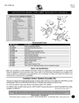
d. Check piston diameter at the point indicated in figure 1. Measure pistons at the widest point across the front and back (perpendicular to wristpin bore). See figure 1.
e. Piston Direction – When installing your pistons onto your rods, position the piston so that the arrow marked on the top will
be pointed in the direction of the intake valve. See figure 1.
f. Ring Installation, use JIMS No.1235 ring expander tool to install rings.
1. Top compression ring has a silver tint on the outside face. If
Valve Pockets
Direction
this ring has an identifying mark (dot), install in top groove of (Directional Pistons Only)
piston with dot facing up. If there is no dot present, install the
silver tinted outer faced ring in the top groove with the
beveled edge facing up.
C.H.
2. Second compression ring has a darker outside face with a bevel
on the inside face. This ring should also have an identifying
mark (a dot). Install in second groove of piston with dot facing
up. If there is no dot, install second ring with beveled edge facing down.
3. Oil control rings are of three-piece design. One inside
expander (Do not shorten expander) and two rails. Install
O.D.
expander with a rail placed below expander and above
expander.
Figure 1
4. Ring Gap Inspection – Both top and second compression ring
end gap to be .016 to .022. With the two oil control rails end gap to be .010 to .050. (Note: If any ring gaps are modified, all burrs must be removed or engine damage can result).
5. Ring gap placement must be per H-D service manual.
6. Install pistons per H-D service manual.
Break In Procedure
After final assembly, the engine must be broken in. Over revving or lugging engine could cause damage to pistons and / or other engine
components. On the initial start up, excessive heat build up can occur. Do not over heat by revving engine or running at a fast idle too
long. To ensure proper head gasket seal upon first time engine start up, idle engine 1000-1500 R.P.M. until cylinder head temperature
reaches about 250 degrees. Shut engine off and let cool. This procedure is necessary to properly seal top end components.
Because most engine damage could occur during the first 50 miles, keep the heat down by not exceeding 2800 R.P.M., but do not lug
engine.
Continue to vary speed for the next 500 miles and do not exceed 3800 R.P.M. for the balance of the first 1000 miles. Avoid overheating engine. Do not lug engine or idle for long periods of time. No trailer towing, racing, etc. Change oil and filter after the first 500
miles.
WARRANTY
All JIMS® parts are guaranteed to the original purchaser to be free of manufacturing defects in material and workmanship for a period of six (6) months
from the date of purchase. Merchandise that fails to conform to these conditions will be repaired or replaced at JIMS® option the parts are returned within the six
(6) months warranty period or within ten (10) Days thereafter.
In the event warranty service is required, the original purchaser must call or write JIMS® immediately with the problem. Some problems can be rectified
by a telephone call and need no further course of action. A part suspected of being defected must not be replaced by a dealer without prior authorization by
JIMS®. If it is deemed necessary for JIMS® to make an evaluation to determine whether the part is defective, it must be packaged properly to prevent further damage and be returned prepaid to JIMS® with a copy of the original invoice of purchase and a detailed letter outlining the nature of the problem, how the part was
used and the circumstances at the time of failure. If after an evaluation has been made by JIMS® and the part was found to be defective, repair, replacement or
credit will be granted.
ADDITIONAL WARRANTY PROVISIONS
1.
2.
3.
4.
5.
JIMS® shall have no obligation in the event a JIMS® part is modified by person or organization.
JIMS® shall have no obligation if a JIMS® part becomes defective in whole or in part as a result of improper installation, improper maintenance,
improper use, abnormal operation, or any other misuse or mistreatment of the part.
JIMS® shall not be liable for any consequential or incidental damages resulting in the failure of a JIMS® part, the breach of any warranties, the failure to deliver, delay in delivery, delivery in non-conforming condition, or for any other breach of contract or duty between JIMS® and a customer.
JIMS® parts are designed exclusively for use in Harley-Davidson® motorcycles. JIMS® shall have no warranty or liability obligation if JIMS® part is used in any other application.
Any damaged or defective product replaced by JIMS® will not be returned under any circumstance.
JIMS, 555 Dawson Drive, Camarillo, Ca 93012 phone 805-482-6913 • Fax 805-482-9224 • www.jimsusa.com
3