1
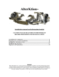
VESTIL MANUFACTURING CORPORATION
2999 North Wayne St. • Angola, IN 46703
Phone (260) 665-7586 • Fax (260) 665-1339
E-mail: [email protected] • www.vestil.com
Revised 0708
A company dedicated to solving ergonomic
and material handling problems since 1953.
OWNER'S
MANUAL
HYDRAULIC DRUM STACKER
MODEL HDC-450-60 / 72 / 84 / 96
Contents
Warnings and Safety Instructions ....................... 1
Receiving Instructions ........................................ 1
Loading Instructions ........................................... 2
Operating Instructions ........................................ 2
Rack Specifications............................................ 3
Periodic Maintenance Instructions ..................... 4
Operation............................................................ 5
Hydraulic Schematic .......................................... 6
Air Bleed Procedure ........................................... 6
WARNINGS & SAFETY INSTRUCTIONS
Read owner's manual completely before operating unit!
* Remove drum & disconnect power before working on unit.
* Do not stand below any part of a raised drum stacker or
drum when unit is running.
* Stand clear of drum while operating the hand crank or
chain crank.
* Use only maintenance parts supplied or approved by the
manufacturer.
* Do not change pressure relief valve setting.
* Never operate stacker/rotator unless you are watching it.
* Never exceed maximum capacity of 800 pounds for FULL
drum: or 500 pounds for HALF-FULL drum.
* Load drum at the center of the cradle.
* Consult factory for uneven loading.
* Do not continue to pump on the foot pump pedal if the
cradle is not raising.
* Do not use brake fluids or jack oils. Use AW-32 hydraulic
oil or equivalent.
* Consult factory if adding or performing any modifications
to the original equipment.
* Make sure all operator safety labels are in place (p.14).
Foot Pump Troubleshooting Guide ............. 7
Hydraulic Drum Stacker/Boom
Exploded Parts Drawing ............................. 8
Parts List .....................................................9
Cradle Assembly
Exploded Parts Drawing ...........................10
Parts List ................................................... 11
Warning Label Identifications .................... 12
Limited Warranty ....................................... 12
Remove all packing and strapping material, inspect
for damage. IF DAMAGE IS EVIDENT, FILE A CLAIM
WITH THE CARRIER IMMEDIATELY! Also, check the unit
size, type of power unit, etc., to ensure the unit is correct for
the intended application.
RECEIVING INSTRUCTIONS
Every unit is thoroughly tested and inspected prior
to shipment. However, it is possible that the unit may incur
damage during transit. If you see damage when unloading
make a note of it on the SHIPPER RECEIVER.
HYDRAULIC DRUM STACKER
HDC-450 SERIES
1
LOADING INSTRUCTIONS
The load capacity rating as inscribed on the
nameplate of your unit designates the net capacity,
assuming the cradle is aligned at the center of the
drum. This capacity must never be exceeded, as
permanent damage or injury may result.
OPERATING INSTRUCTIONS
DRUM STACKER
Remove Hydraulic Drum Stacker (HDC450), from the crate. Check carefully for damage
and report any damage immediately. When using
the Hydraulic Drum Stacker, you can either lift up
the drum horizontally or vertically.
HORIZONTAL DRUM POSITION
For horizontal drum position, lower the
cradle near floor position until you can slide in the
cradle along the side of the drum. Open carrier
cradle full width and hook cradle chain on stud.
Move the unit in until the end of the cradle touch
the end of the drum. Lock drum in place by clinching chain with ratchet tightener.
END OF CRADLE
In both situations, raise the cradle until the
drum is 3 - 4 inches above the ground before
moving. It is recommended, but not required, the
drum to be moved in a VERTICAL position.
Remove control chain from box and place end of
loop near operator. When stacking, rotate drum
to the HORIZONTAL position.
Always stay clear of moving parts. The
cradle will rise as the foot pedal is pumped.
Depressing the release lever will lower the cradle
at a control rate of descent.
In the event the unit is overloaded, the
relief valve will open because of excessive pressure build up, and oil will bypass into the reservoir.
TO ROTATE DRUM:
Pull on chain, rotating drum to horizontal
position for stacking. For best control of drum
rotating angle, pay out one side of the loop while
pulling in the other.
** For model HDC-450-60, the drum is rotated
using a hand crank instead of chain crank.
** When elevation is not required, transport
the drum in the lowered position.
Figure 1
VERTICAL DRUM POSITION
For vertical drum position, rotate the cradle
to vertical position and lower the cradle until the
end of the cradle is the same height as the top of
the drum. Open carrier cradle full width and hook
cradle chain on stud. Move the unit in until the
side of the drum touches the cradle. Once again,
lock drum in place by clinching chain with ratchet
tightener.
END OF CRADLE
2
Figure 2
BOOM
The HDC-450 series may also be used as
a hoist using the boom supplied with unit. The
boom is stored conveniently on one of the lower
straddle legs. Simply remove the 3/4" diameter
pin from carriage and position boom on top of
carriage, align holes and replace pin and clip.
Lifting capacity for boom at hook position is 800
pounds. This capacity and load center must never
be exceeded.
SAFETY INSTRUCTIONS FOR THE OPERATOR
1.) The HDC-450 series has a MAXIMUM CAPACITY RATING of 800 pounds FULL, and 500 pounds
HALF-FULL, and is intended for lifting, moving, and stacking 55 GALLON steel drums. Do not exceed
these ratings as the unsafe condition that may result could cause damage or excessive wear, or make
the unit awkward to handle.
2.) Always load the unit properly. Make sure the end/top of the drum is touching the end of the cradle.
3.) When operating, loading, unloading, or maintaining your drum stacker, always use care and good
judgement, have good footing and a firm hold. Keep hands and loose clothing etc., away from all
moving parts. Never allow anyone to be below any part of a raised drum stacker, drum, or boom. Please
read all instruction THOROUGHLY before attempting to operate your new drum stacker.
4.) Do not allow drum to impact on floor, ground, or dumping station etc., or there may be damage.
5.) Never use the unit if the cradle is in need of repairs or in the case of a malfunction.
6.) Notify your maintenance personnel or supervisor in case you notice anything out of the ordinary, such
as binding, odd noises, appearance of oil, etc.
7.) Do not continue to pump on the foot pedal if the cradle is not raising. The foot pump may be
permanently damaged. Relieve system pressure by depressing the release lever.
8.) It is recommended, but not required, the drum to be moved in a VERTICAL position. When
stacking, rotate the drum to HORIZONTAL position.
RACK SPECIFICATIONS FOR THE HORIZONTAL DRUM STACKER (HDC-450 SERIES)
8
8
1/4
O 24
FLOOR
12
32
3
PERIODIC MAINTENANCE INSTRUCTIONS
BE SURE ALL POWER IS OFF BEFORE ATTEMPTING TO WORK ON THIS EQUIPMENT!
CAUTION: SERVICE WORK SHOULD BE PERFORMED ONLY BY TRAINED & QUALIFIED PERSONNEL
(A) Before Each Use Check For The Following
1.)
2.)
3.)
4.)
5.)
Oil leaks.
Worn or damaged hose.
Structural deformation of cradle or frame.
Unusual noise or binding.
Check casters for proper operation.
Do not use if there are any of the above!
(B) Monthly Inspections
1.)
Check oil level. Oil should be 1" to 1 1/2" below the top of the tank with the
cradle in the fully lowered position. Add as necessary.
2.)
Check for oil leaks.
3.)
Check for worn or damaged hose.
4.)
Check clevis and pivot points for wear.
5.)
Periodically inspect all moving parts, framework, and contact areas for sign
of wears, fatigue or loosening.
Tighten, adjust or replace parts as necessary to prevent failure and
maintain proper function.
6.)
Check oil cradle hinges, ratchet, pawl, chain and other moving parts
periodically.
7.)
Lubricate gear-train once a month with a good grade lubricant.
There are three grease fittings on the gear block, and one grease fitting in
the idler bearing block.
8.)
Check for unusual noise.
9.)
Clean off dirt and debris.
10.)
Make sure all warning labels are in place and in good condition (p.14).
(C) Yearly Inspection
Hydraulic oil should be changed at least once a year, or sooner if the oil
darkens or becomes gritty. Flush reservoir before refilling. Presence of
water is indicated if the oil turns milky. Recommended oil: AW-32
Hydraulic fluid or equal.
All maintenance work must be performed by qualified personnel with
training in the repair of electrical and hydraulic components
4
OPERATION
Warning: Keep all personnel clear of the machine when it is in operation. Be certain no part of any
person or object is under any part of the platform before lowering the unit.
Caution: Always carefully watch cradle and any load on it when it is in operation.
Do not exceed a rate of two feet per second when transporting a load with the drum stacker.
• The standard manually-powered stacker is furnished with a two-speed foot pump. Under empty or
low load conditions, the pump pushes a higher volume of fluid to the cylinder and thus lifts the platform
with fewer foot strokes. With a moderate to full load, the pump will automatically reduce its output in
order to generate the required hydraulic pressure.
• To lift the platform, simply repeatedly press the foot pump's foot treadle. To lower the platform, press
the small lever at the left corner of the pump with your toe. The unt will hold its position when the
lowering lever is released.
VELOCITY FUSE OPERATION
There is a brass velocity fuse with a stainless steel spring in the base of each cylinder. In the
event of a hydraulic hose or fitting failure, the cradle starts to lower at a fast rate. As soon as the descent speed exceeds the fuse's preset speed, the velocity fuse will shut off the oil flow and the cradle
will remain nearly stationary until pressure is reapplied (after repairs are done). This safety feature
reduces the possibility of accidental personal injury or damage to the unit or its loads. If air is introduced into the system, the velocity fuse can lock up even though no failure has occurred. To reset the
velocity fuse just activate pump by depressing the "UP" button. Remove the load and follow the
cylinder air bleed procedures on page 6.
5
AIR BLEED PROCEDURE
If your unit descends very slowly or will not descend at all, air could be trapped in the hydraulic
circuit and must be "bled" from the system. The Hydraulic Drum Stacker (HDC-450 Series) utilizes a
"bleeder" fitting at the end of the cylinder near the cross tube. If you experience the above, follow
these directions.
1.)
2.)
3.)
4.)
5.)
Remove the drum from the cradle.
Raise the unit.
If available, place a 1/4" plastic hose over the cylinder bleeder screw.
Loosen the bleeder screw at the top of the cylinder approximately 1/4 to 1/2 turn to allow
trapped air to escape.
When the cylinder is free of air, tighten the bleeder screw and remove the plastic hose.
Air can also become trapped in the foot pump.
Please refer to page 8 for the foot pump air bleed procedure.
HYDRAULIC SCHEMATIC
1.5" x 18" DISPLACEMENT CYLINDER
WITH INTERNAL VELOCITY FUSE
6
Trouble shooting Guide for Single and Two-speed Hydraulic Foot Pump
Possible Cause
Observation
1.)
2.)
Cradle does not raise
Foot pedal goes down hard but
cradle does not raise
Unit will pump under no load or
when rapidly stroked, or pedal will
stroke without pumping
*Refer to exploded view
a.
b.
Excessive load
Oil is low
a.
b.
c.
d.
Pinched hose
Relief valve set too low
c.
d.
a.
Particle of dirt under the pressure
relief valve
Particle of dirt under inlet check valve
a.
c.
d.
Pump is air locked
Inlet check valve has foreign material on
seat
Relief setting is out of adjustment
Foreign material on relief valve seat
a.
b.
c.
d.
Bleed air from system inlet
Remove and clean inlet ball and seat
Adjust relief setting higher
Lowering valve has foreign material on the
seat or is stuck in the open position
b.
3.)
Remedy
a.
b.
b.
Remove part of the load
Fill oil to within one inch of the top of the
reservoir
Correct as necessary
Increase only as necessary
Lower cradle - Disassemble, clean and re
assemble pressure relief valve*
Lower cradle - Disassemble, clean and re
assemble inlet check valve*
4.)
Cradle raises when the pump is
stroked but lowers on return stroke
a.
Outlet check is leaking
a.
Clean foreign material from ball and seat
5.)
Cradle raises but takes too much
effort
a.
Change pump displacement speed
a.
Slide locking collar back
6.)
Cradle raises but is too slow
a.
b.
Change pump displacement speed
Intake filter clogged
a.
b.
c.
Foreign material stuck under pressure relief
valve or under inlet check valve
c.
Slide locking collar forward
Lower cradle - drain reservoir, clean and
flush debris, refill with clean oil
Lower cradle - Disassemble, clean and re
assemble pressure relief valve*
a.
Check for foreign material stuck in clevis or
pivot points or frame rails
Oil is low
a.
Correct as necessary
b.
Fill oil to within one inch of the top of the
reservoir
Pinched hose
Intake filter clogged
Foreign material lodged in velocity fuse
Foreign material lodged in pressure
compensated flow control valve
a.
b.
c.
Correct as necessary
Correct as necessary
Lower cradle - Disassemble, clean and re
assemble
Lower cradle - Disassemble, clean and re
assemble pressure relief valve*
a.
Foreign material lodged in pressure
compensated flow control valve
a.
Lower cradle - Disassemble, clean and re
assemble pressure relief valve*
a.
Foreign material lodged in pressure
compensated flow control valve
Release pin bent or missing
Foreign object blocking roller travel
Velocity fuse is locked
a.
Lower cradle - Disassemble, clean and re
assemble pressure relief valve*
Replace as necessary
Correct as necessary
Remove air from hydraulic system, to un
lock, repressurize system
7.)
Spongy or jerky operation
b.
8.)
9.)
Cradle lowers too slow
Cradle lowers too fast
10.) Cradle raises but does not lower
a.
b.
c.
d.
b.
c.
d.
d.
b.
c.
d.
7
HDC-450 SERIES HYDRAULIC DRUM CARRIER/ROTATOR
7
6
17
7
6
16
1
13
12
7
6
15
2
14
7
10
6
8
4
9
3
5
8
PARTS IDENTIFICATION
HDC-450 SERIES HYDRAULIC DRUM CARRIER/ROTATOR
DESCRIPTION
PART NO.
QTY
1
HDC cradle ass'y (see pages 6 & 7)
09538005
1
2
Hydraulic cyl., 1-1/2" dia. x 18" [HDC-450-60/72/84]
09021004
1
Hydraulic cyl., 1-1/2" dia. x 18" [HDC-450-96 only]
09021004
2
3
Wheel, caster
16132036
2
4
Locking hex nut, 1/2"-20
A/L
2
5
Hex head cap screw, 1/2"-20 x 3-1/2"
A/L
2
6
Clevis pin, 3/4" dia. x 3-3/8"
09112006
4
7
Hitch pin clip, # 11 (Fastenal)
45285
4
8
Floor brake
16132080
1
9
Hex nut, 3/8"-16
A/L
4
10
Reservoir
15023001
1
11
Two-speed hydraulic foot pump (not shown)
250550
1
12
Handle grip
AL
2
13
Hex head cap screw, 3/8"-16 x 1"
A/L
4
14
Reservoir hose
09623001
1
15
Hydraulic hose (HDC-450-60)
09623002
1
Hydraulic hose (HDC-450-72)
09623003
1
Hydraulic hose (HDC-450-84)
09623004
1
Hydraulic hose (HDC-450-96)
09623005
1
16
Spring pin, 3/16" x 1-1/2" (HDC-305-60 only)
A/L
1
17
Boom
09514031
1
ITEM NO.
A/L Available at local hardware store
9
10
30
29
28
31
PARTS DIAGRAM FOR CRADLE ASSEMBLY (DRUM CARRIER/ROTATOR
HDC-450 SERIES
PARTS DIAGRAM FOR CRADLE ASSEMBLY (DRUM CARRIER/ROTATOR
HDC-450 SERIES
DESCRIPTION
PART
NUMBER
Hand wheel ( HDC-450-60 only)
Chain wheel (HDC-450-72/84/96 only)
1A-P
1-P
1
1
#1/0 Babbitt lock link chain (20") (HDC-450-72/84/96 only)
Chain wheel shaft w/triangle & bolts (HDC-450-72/84/96 only)
2-P
3-P
1
1
Bolt & nut, 5/16-18 x 1" (HDC-450-72/84/96 only)
Bearing, 3/4" ID x 2-1/2"
35-P
01111048
3
1
Grease fitting Alemite (1608B)
Washer, 3/4" SAE
33-P
09113004
4
5
Sprocket (12T # 35)
Roller chain (# 35-3/8" pitch)
09042004
09042006
1
1
Sprocket (36T # 35)
Pinion gear (7T) w/key
09042003
09042007
1
1
Hinge pine & nuts
Pawl shoulder screw and nut
157-P
170-P
2
1
Pawl spring
Pawl
169-P
168-P
1
1
Snap ring
Ratchet
166-P
165-P
1
1
Handle grip
Pawl & ratchet hinge plate
136-P
09516006
180-P
1
1
1
155-P
09516007
1
1
20-P
7-P
1
2
09113005
09145001
1
2
21-P
09113006
2
2
01111047
09145003
1
1
09538005
1
ITEM
NUMBER
1a
1
2
3
4
5
6
7
8
9
10
11
12
13
14
15
16
17
18
19
20
21
22
23
24
25
26
27
28
29
30
31
Binder chain
Chain bolt & nut (3/8"-16 x 2-1/2" HHMS)
Chain hinge plate
Spacer (3/4" ID)
Bearing (Randall SH186)
Bearing block
Collar (3/4" ID)
Washer & nut
Spur gear spacer
Bearing, 1" ID x 2-1/2"
Collar (1" ID)
Cradle assembly for 55 gal. steel drum
QUANTITY
11
WARNING LABEL IDENTIFICATION
MAKE SURE ALL WARNING LABELS ARE IN PLACE!
1
USE AW-32 HYDRAULIC
OIL OR
EQUIVALENT
*Product safety signs or labels should be periodically
inspected and cleaned by the product users as necessary
to maintain good legibility for safe viewing distance ...
ANSI 535.4 (10.21)
Contact manufacturer for replacement labels.
LIMITED WARRANTY
ONE YEAR LIMITED WARRANTY. The manufacturer warrants for the original purchaser against defects
in materials and workmanship under normal use one year after date of purchase. (Not to exceed 15 months after
date of manufacture.) Any part which is determined by the manufacturer to be defective in material or workmanship
and returned to the factory, shipping costs prepaid, will be, as the exclusive remedy, repaired or replaced at our
option. Labor costs for warranty repairs and/or modifications are not covered unless done at manufacturer’s
facilities. Any modifications performed without written approval of the manufacturer may void warranty. This limited
warranty gives purchaser specific legal rights which vary from state to state.
LIMITATION OF LIABILITY. To the extent allowable under applicable law, the manufacturer’s liability for
consequential and incidental damages is expressly disclaimed.
The manufacturer’s liability in any event is limited to, and shall not exceed, the purchase price paid. Misuse or
modification may void warranty.
WARRANTY DISCLAIMER. Our company has made a diligent effort to illustrate and describe the products
shown accurately; however, such illustrations and descriptions are for the sole purpose of identification, and do not
express or imply a warranty that the products are merchantable, or fit for a particular purpose, or that the products
will necessarily conform to the illustrations or descriptions.
The provisions of the warranty shall be construed and enforced in accordance with the UNIFORM
COMMERCIAL CODE and laws as enacted in the State of Indiana.
DISPOSITION. Our company will make a good faith effort for prompt correction or other adjustment with
respect to any product which proves to be defective within the Limited Warranty. Warranty claims must be made
in writing within said year.
12