1
US 20060056616A1
(19) United States
(12) Patent Application Publication (10) Pub. No.: US 2006/0056616 A1
Heimbrock
(43) Pub. Date:
Mar. 16, 2006
(54)
HOSPITAL TELEPHONE AND DEVICE
CONTROLLER
(76)
Inventor:
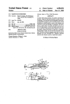
Publication Classi?cation
(51)
Richard H. Heimbrock, Cincinnati,
Int. Cl.
H04M 1/00
H04M 9/00
OH (US)
(52)
Correspondence Address:
BARNES & THORNBURG
11 SOUTH MERIDIAN
(57)
US. Cl.
(2006.01)
(2006.01)
...................................................... .. 379/428.01
ABSTRACT
INDIANAPOLIS, IN 46204
(21) Appl. No.:
11/216,202
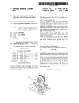
A hand-held pendant operating as a telephone and a con
(22) Filed:
Aug. 31, 2005
ratus is disclosed. The hand-held pendant has a complemen
tary holster Which mounts in the siderail of the patient
troller of one or more functions of a patient-support appa
support apparatus and serves to retain the hand-held
Related US. Application Data
pendant. The hand-held pendant has tWo sides, one func
(60)
Provisional application No. 60/608,979, ?led on Sep.
10, 2004.
334
'8 I30 .28 80 334
I
H6
26
82
32
242
32
tioning as a telephone and the other as a controller for one
or more functions of a patient-support apparatus.
Patent Application Publication Mar. 16, 2006 Sheet 1 0f 8
US 2006/0056616 A1
Patent Application Publication Mar. 16, 2006 Sheet 2 0f 8
US 2006/0056616 A1
Patent Application Publication Mar. 16, 2006 Sheet 3 0f 8
US 2006/0056616 A1
Patent Application Publication Mar. 16, 2006 Sheet 4 0f 8
US 2006/0056616 A1
Patent Application Publication Mar. 16, 2006 Sheet 5 0f 8
330
I2
5
r"
I48
FIE £2
I60
i}
| 52
US 2006/0056616 A1
Patent Application Publication Mar. 16, 2006 Sheet 6 0f 8
ML
290‘/@g@
29i_,@@@
292% 6%
/ ®®@
184
346
296
®@@
US 2006/0056616 A1
I
Q
348
3: 2O ‘_
I84
/
0 OTHER (éONTROLS
0 CALL CAREGIVER
298
“
o INTERNET
o MEDICALINFO'
POWER
J84
CH. UP
/
282 ,Fj‘k 322
0 GAMES
288“
/
3'4
3'6
<1 28%
'
t
5
VOL.
[E ~
3l8
VOL.
W CH. DN up
/
284
Patent Application Publication Mar. 16, 2006 Sheet 7 0f 8
US 2006/0056616 A1
Patent Application Publication Mar. 16, 2006 Sheet 8 0f 8
NURSE
STATION‘
DEVICE
CONTROLS
TELEPHONE
SYSTEM
US 2006/0056616 A1
Mar. 16, 2006
US 2006/0056616 A1
HOSPITAL TELEPHONE AND DEVICE
CONTROLLER
include a cord coupling the pendant to the patient-support
apparatus. The cord may pass through an arm of the support
structure.
RELATED APPLICATIONS
[0008] The pendant may be substantially Waterproof. The
[0001] This application claims the bene?t, under 35
U.S.C. § 119(e), of US. Provisional Patent Application Ser.
No. 60/608,979 ?led Sep. 10, 2004 Which is hereby incor
porated by reference herein in its entirety.
pendant may further comprise a disposable sanitary cover.
The pendant may have tWo sides, With a ?rst side having a
user interface dedicated to the functions of the patient
support apparatus and a second side being dedicated to a
user interface for a telephone. Alternatively, the pendant
[0002]
BACKGROUND OF THE INVENTION
may further comprise a touchscreen user interface.
The present disclosure relates to a pendant to be
[0009] In some embodiments, the pendant may further
comprise a Wireless connection to the patient-support appa
used in a hospital or other healthcare facility room for a
patient to control various devices and equipment in the room
or to communicate externally from the room. More particu
larly, the present disclosure relates to a pendant operating as
both a controller and telephone With improved positioning
so that it is readily accessible by the patient.
[0003]
Various types of controllers and communication
devices are knoWn in the healthcare environment. Control
lers coupled to hospital beds, bedside cabinets, and Walls are
knoWn. Communication devices such as phones and nurse
call apparatus are knoWn to be coupled to hospital beds,
bedside cabinets, and Walls as Well. Controllers may control
any of a number of devices including the bed, mattress,
lighting, television, radio, heating or air conditioning. Com
munications devices may include nurse call systems, tele
phones, and intercoms Which are separate from controllers
for bed functions.
ratus. In other embodiments, the retraction of the cord may
be accomplished With the use of a Weight on the cord
outboard of the siderail Which tends to pulls the cord through
the holster When the user stoWs the pendant. In one embodi
ment, the holster is omitted and the pendant is con?gured to
couple directly to the siderail for storage.
[0010] Additional features, Which alone or in combination
With any other feature(s), including those listed above and
those listed in the claims, may comprise patentable subject
matter and Will become apparent to those skilled in the art
upon consideration of the folloWing detailed description of
illustrative embodiments exemplifying the best mode of
carrying out the invention as presently perceived.
BRIEF DESCRIPTION OF THE DRAWINGS
[0011] The detailed description particularly refers to the
accompanying ?gures in Which:
SUMMARY OF THE INVENTION
[0004]
The present invention comprises one or more of the
features recited in the appended claims and/or the folloWing
features Which, alone or in any combination, may comprise
patentable subject matter:
[0005]
In one embodiment of the invention a patient
support apparatus comprises a frame, a patient-support deck
supported on the frame, a mattress supported on the patient
[0012] FIG. 1 is a perspective vieW of a patient-support
apparatus shoWing the patient side of a holster coupled to a
siderail, With a hand-held pendant stoWed in the holster;
[0013] FIG. 2 is a perspective vieW of a patient-support
apparatus shoWing the outboard side of a holster coupled to
a siderail, With a Weighted cord used to retract a hand-held
pendant cord;
support deck, and a siderail coupled to the frame adjacent
the mattress. The patient-support apparatus may further
comprise a holster and a pendant supported by the holster.
[0014]
The pendant may function as both a telephone and a con
troller to receive user inputs that control at least some of the
[0015]
functions of the patient-support apparatus.
[0006] The holster may be attached to the siderail and
moveable to a plurality of positions. The holster may be
FIG. 3A is a perspective vieW of the patient side of
a holster With a hand-held pendant extending from the
holster;
FIG. 3B is a perspective vieW of the backside of
the holster of FIG. 3A With a hook in an extended position;
[0016] FIG. 4 is a front vieW of a hand-held pendant
shoWing buttons useable to control functions of a patient
support apparatus;
con?gured to hold the pendant until the pendant is removed
from the holder. The pendant may have a cord connecting
the pendant to an interface for a patient-support apparatus
control and a telephone system. The cord may pass through
the holster With some slack being stored in the holster. The
cord may be retracted into the holster by a clock spring
mechanism.
[0007] In another embodiment, the holster may be coupled
[0017]
FIG. 5 is a side vieW of the hand-held pendant of
FIG. 4;
[0018] FIG. 6 is a back vieW of the hand-held pendant of
FIG. 4 shoWing buttons useable to control the telephone
functions of the pendant;
[0019]
FIG. 7 is a perspective vieW of an alternative
embodiment of a holster coupled to a ?exible member of a
to a support structure. The support structure may be coupled
to the patient-support apparatus or to a piece of furniture in
the room. The support structure may receive the holster and
be movable by a user to a plurality of positions. In still
another embodiment, the holster may be coupled to a
support structure that is attached to a structure in the patient
support structure being movable along the mounting bar
betWeen a ?rst position (in solid) and a second position (in
room such as a Wall or the ceiling. The support structure may
phantom), and the support structure includes a ?exible arm
support arm;
[0020] FIG. 8 is a perspective vieW of a hospital bed With
a support structure coupled to the bed by a mounting bar, the
Mar. 16, 2006
US 2006/0056616 A1
movable to support a holster and a hand-held pendant
carried by the holster in a variety of positions;
[0021]
FIG. 9 is a perspective vieW of the support struc
ture of FIG. 8 coupled to a chair instead of a bed;
[0022]
FIG. 10 is a perspective vieW of the support
structure of FIG. 8 coupled to an overbed table instead of a
bed;
[0023]
FIG. 11 is a perspective vieW of another embodi
ment of a support structure mounted to a horiZontal track
member that is mounted to a room Wall;
[0024]
FIG. 12 is a perspective vieW shoWing an alterna
tive embodiment of a support structure having an articulated
arm mounted to a patient room Wall, a display coupled to an
end of the articulated arm, a holster coupled to the display
screen, and a pendant carried by the holster;
to holster 26 by snap-?t. A cord 32 couples pendant 20 to
patient-support apparatus 10. Cord 32 extends from holster
26 to pendant 20 through a retraction mechanism 76. When
pendant 20 is stoWed in holster 26, cord 32 spools into
retraction mechanism 76 so as to remove any slack.
[0034] Referring to FIGS. 2, 3A, and 3B, holster 26 a
body 118 Which occupies a portion the siderail opening 116
and a ?ange 114 Which extends beyond the siderail opening
116 to engage the siderail 18 When the holster 26 is posi
tioned in the siderail opening 116. Flange 114 extends
beyond the exterior periphery of body 118 and generally has
a peripheral shape similar to the shape of the periphery of
body 118. The back of body 118 has an upper concave
surface 122, a loWer concave surface 123, a left side surface
260, a right side surface 252, and a back surface 258.
Concave surfaces 122, 123 have concavity folloWing axes
extending along the horiZontal Width of body 118. Concave
[0025] FIG. 13 is a perspective vieW of an alternative
embodiment of a hand-held pendant Wherein the hand-held
surfaces 122, 123 are complementary to tWp convex surfaces
pendant has a touchscreen display;
116. The front of body 118 has a cavity 262. A surface 350
that is internal to cavity 262 and at the back of cavity 262 is
shaped to conform to the surface of the second side of
[0026]
FIG. 14 is a screen shot of the pendant of FIG. 13
shoWing the touchscreen con?gured to control telephone
functions of the pendant;
[0027] FIG. 15 is a screen shot of the pendant of FIG. 13
shoWing the touchscreen con?gured as an interactive menu;
[0028] FIG. 16 is a screen shot of the pendant of FIG. 13
shoWing the touchscreen con?gured to operate as an input
device to alter television channel and volume settings;
[0029] FIG. 17 is a perspective vieW of a patient-support
apparatus With another embodiment of a pendant stoWed
directly into the opening of a siderail and a ?rst side of the
pendant facing toWard a patient and having buttons to
control functions of the patient-support apparatus;
[0030]
FIG. 18 is a perspective vieW of a second side of
the pendant of FIG. 17 shoWing the pendant having buttons
useable to control telephone functions of the pendant; and
[0031] FIG. 19 is a perspective vieW, partly diagrammatic,
of a hospital room illustrating a hand-held pendant Wire
lessly communicating With a telephone system and With
other devices.
DETAILED DESCRIPTION OF THE DRAWINGS
[0032] Ahand-held pendant 20 shoWn in FIG. 1 functions
as both a telephone and a controller to receive inputs from
a user to control one or more functions of a patient-support
apparatus 10. The patient-support apparatus 10 has a frame
12, a patient-support deck 14, a mattress 16, a pair of
siderails 18, and a holster 26 in Which hand-held pendant 20
is carried. Patient-support deck 14 is located above frame 12
and supports mattress 16 Which is placed on top of patient
support deck 14. Apatient 70 lies on mattress 16. Siderails
18 are adjacent to mattress 16 and are coupled to frame 12
for movement betWeen raised positions, shoWn in FIG. 1,
and loWered positions (not shoWn) doWn aWay from mat
tress 16 When not in use.
128, 129 of the upper and loWer portions of siderail opening
pendant 20 comprising the telephone functions such that
pendant 20 may only be stoWed With patient-support appa
ratus function controls exposed. The interior surface (not
shoWn) of upper side 256 and an interior surface 352 of
loWer side 250 are shaped to receive the exterior pro?le of
pendant 20.
[0035] Flange 114 extends internally beyond a loWer sur
face 352 and an upper side surface (not shoWn) of body 118
partially covering cavity 262 and forming a lip 120 Which
serves to retain pendant 20 When it is stoWed in holster 26.
Lip 120 is siZed such that pendant 20 slips past lip 120 Which
?exes When stoWing or removing force is placed on lip 120.
Holster 26 has angled cut-outs 78 and 79 to permit gripping
access by patient 70 to remove pendant 20 from holster 26.
Angled cut-out 78 begins at the interior intersection of
surface 350 and the upper side surface (not shoWn). A
surface 264 is formed and extends at an angle obtuse to
surface 350 until surface 264 intersects With ?ange 114.
Angled cut-out 79 begins at the interior intersection of
surface 350 and loWer surface 352. A surface 265 is formed
and extends at an angle obtuse to surface 350 until surface
264 intersects With ?ange 114. Angled cut-outs 78, 79 are
horiZontally centered in cavity 262 and have a Width Which
is approximately one-third of the horiZontal Width of cavity
262. Aright side surface 354 of cavity 262 has a passage 268
for cord 32 to pass from retraction mechanism 76 to pendant
20.
[0036] When holster 26 is placed into siderail opening
116, concave surfaces 122, 123 snap over convex surfaces
128, 129 resulting in a removable and slidable coupling of
holster 26 to siderail 18. As indicated by arroWs 334 in FIG.
2, holster 26 is con?gured to slide Within siderail opening
116 to a number of positions Within the longitudinal length
of opening 116. Body 118 is constructed of a material having
suf?cient ?exibility to alloW tWo edges 272, 273 to slip past
convex surfaces 128, 129 providing retention of holster 26
Referring noW to FIGS. 1 and 2, holster 26 is
in siderail opening 116. The freedom of movement of holster
couples to siderail 18. Holster 26 includes a releasable latch
28 Which retains holster 26 in the siderail. Latch 28 is spring
26 in siderail opening 116 permits the sliding movement of
holster 26 to adjust the position of holster 26 Within siderail
opening 116. To minimiZe unWanted movement, releasable
latch 28 provides a positive engagement betWeen holster 26
[0033]
loaded to provide positive engagement betWeen holster 26
and siderail 18 until released by a user. Pendant 20 couples
US 2006/0056616 A1
Mar. 16, 2006
and siderail 18. Releasable latch 28 is biased to an engaged
storage position. Cord 32 extends from holster 26 to inter
position pressing releasable latch 28 against convex surface
128 of siderail 18. Releasable latch 28 is retained in body
face box 112 Where telephone signals are split from patient
support apparatus 10 controller signals.
118 Which has a cavity 130 to permit releasable latch 28 to
pass beloW edge 272 of body 118 as holster 26 is inserted
into siderail opening 116. The releasable latch 28 bias must
be overcome to insert holster 26 into siderail 18.
[0037] Upon installation, an extension spring (not shoWn)
forces the releasable latch 28 upWard against convex surface
128 to provide positive engagement With the siderail 18.
Holster 26 slides Within siderail opening 116 When sufficient
force is applied to holster 26 parallel to concave surfaces
122, 123 and convex surfaces 128, 129. In other embodi
[0041] Referring noW to FIGS. 3A, 4, and 6, pendant 20
is contoured in shape With a grip area 96, a speaker area 98,
and a mouthpiece area 100. Pendant 20 further comprises
tWo sides Wherein a ?rst side 86 has user input devices
associated With bed control functions and a second side 88
has user input devices associated With telephone functions.
The overall shape of pendant 20 provides an intuitive feel for
the orientation of the device in use. Pendant 20 further
by other devices suitable for creating bias including torsion
comprises plurality nodules 110 Which protrude from the
perimeter of pendant 20. Nodules 110 provide a discontinu
ous edge surface to absorb shock and provide improved
gripping of the pendant 20. The outer housing of pendant 20
is constructed of plastic in some embodiments, although any
material(s) of suitable strength may be used.
springs, releasable latch being a ?exible member attached to
body 118, or other biased constructions knoWn to those of
ordinary skill in the art. In still further embodiments, holster
26 does not slide relative to siderail 18 due to the coupling
tion buttons 90, selector buttons 52, and a nurse call button
50. Function buttons 90 are selectable, such as by pressing,
to choose a function of the bed to be operated. In the
mechanism used, such as screWs or rivets, for example, or
illustrative embodiment, functions include control of the
ments, mating of concave surfaces 122, 123 to convex
surfaces 128, 129 may be replaced by other complementary
linear shapes Which mate to facilitate linear sliding motion.
In some embodiments, bias of latch 28 may be accomplished
due to holster 26 occupying substantially all of the opening
or other holster-receiving space provided in siderail 18.
[0038] Body 118 has an internal passage (not shoWn)
routing electrical cord 32 from a cord inlet 132 to retraction
mechanism 76. Astrain relief 132 is provided at the interface
betWeen cord 32 and body 118 adjacent inlet 133. Retraction
mechanism 76 is retained in holster 26 by a right side Wall
252 of cavity 262. When stoWed, pendant 20 is retained
behind lip 120. Angled cut-outs 78, 79 on holster 26 are
positioned complementary to a grip area 96 on pendant 20.
The internal perimeter of ?ange 114 is siZed to match the
external periphery of pendant 20 such that pendant 20 can
only be stoWed With electrical cord 32 positioned at the same
end of holster 26 as retraction mechanism 76.
[0039]
In an alternative embodiment, cord 32 further com
[0042] First side 86 further comprises a speaker 46, func
height of patient-support apparatus 10 and articulation func
tions of patient-support apparatus 10 including head eleva
tion and knee elevation. In other embodiments, functions
controlled may include other patient controlled devices such
as television channel up, channel doWn, volume up, volume
doWn, radio, audio, direct lighting, or indirect lighting.
Selector buttons 52 permit the user to provide input to the
selected function. For example, if the television function is
selected, selector buttons 52 Will alter channel and volume
settings on the television. Nurse call button 50 is used by
patient 70 to engage communication With caregiver staff at
a location remote from the patient room 38. Selector buttons
52, function buttons 90, and nurse call button 50 are all
back-lit to improve visibility of the respective buttons in loW
light situations and include raised areas to improve locating
of the buttons by tactile feel, and provide an auditory
prises a Weight 242 Which is coupled to cord 32 outboard of
feedback that the button has been activated. While certain
holster 26 and siderail 18 as shoWn in FIG. 2. In this
embodiment, holster 26 does not have retraction mechanism
functions are described herein, a person of skill in the art Will
appreciate that there are many other functions not listed
76, but rather, cord 32 extends through a passage (not
shoWn) in holster 26. Weight 242 tends to pull slack in cord
herein Which may be controlled by pendant 20.
32 through holster 26 When a user stoWs pendant 20. Also in
this embodiment, an end of cord 32 spaced from pendant 20
plugs into a receptacle elseWhere on patient-support appa
ratus 10 or in the patient room.
[0040] Holster 26 has a hook 80, seen in FIGS. 2 and 3B,
Which is extendable from the back of holster 26 and is used
as an alternative to placing holster 26 in siderail opening
116. Hook 80 pivots When moving betWeen a use position,
shoWn in FIG. 3B, and a storage position, shoWn in FIG. 2.
Hook 80, When used, hooks over the top edge of siderail 18.
Hook 80 is biased to a storage position by a torsion spring
(not shoWn). When hook 80 is placed over a portion of a
patient-support apparatus 10, such as a siderail 18, having a
thickness smaller than hook 80 can accommodate in its fully
extended position, then hook Will pivot under the bias of the
torsion spring to clamp the portion of the patient-support
apparatus 10 betWeen an end portion 270 of hook 80 and
back side 258 of pendant 20. Holster 26 has a cavity 84 in
back surface 258 adapted to receive hook 80 When in the
[0043] Audio signal from remote staff, television, or radio
are communicated to patient 70 by speaker 46. Patient 70
uses microphone 56 to speak to caregiver staff that is remote
to the patient room 38. Second side 88 of pendant 20
comprises a telephone. Second side 88 has a speaker 164, a
microphone 168, a keypad 54, a display 92, function buttons
166, and dial button 94. Speaker 164 delivers audio to
patient 70 from the telephone. Patient 70 speaks into the
telephone through microphone 168. Keypad 54 is used to
enter telephone numbers to be dialed. Display 92 provides a
visual display of the number dialed by patient 70. Addition
ally, display 92 displays caller ID information and text to
patient 70 as appropriate. Function buttons 166 provide
additional menu driven functionality With the menu choices
displayed on display 92. Dial button 94 dials the number
entered into the telephone and displayed on display 92. Dial
button 94 is also used to disconnect telephone connections
When the call is complete. Key pad 54, display 92, function
buttons 166, and dial button 94 are all back-lit to improve
visibility of the respective buttons in loW light situations and
Mar. 16, 2006
US 2006/0056616 A1
include raised areas to improve locating of the buttons by
tactile feel, and provide an auditory feedback that the button
has been activated.
support structure 40.
[0044] Another embodiment, shoWn in FIGS. 8, 9, and 10,
[0048]
comprises a support structure 40 With a ?rst end 134 coupled
to a mounting bar 66 and a second end 136 coupled to a
holster 138, With mounting bar 66 coupled to a device such
coupled to a structure 42 that is attached to a Wall 148 of a
hospital room as shoWn in FIG. 11. Support arm 150
as a patient-support apparatus 10, a chair 60, or an overbed
table 62. Mounting bar 66 is coupled to the device. Illus
tratively, mounting bar 66 is coupled to a head section of
apparatus 10 as shoWn in FIG. 8, to an arm 336 of chair 60
as shoWn in FIG. 9, and to an end of table section 338 of
overbed table 62. First end 134 is coupled to mounting bar
66 by a clamp 64 lockable on mounting bar 66 in a plurality
of positions. Support structure 40 is adjustable to position
second end 136 in a plurality of positions. Holster 138 is
coupled to second end 136.
[0045] Holster 138 is con?gured to receive a pendant 20 as
shoWn in FIG. 7. Holster 138 comprises tWo opposing arms
144 on each side, the arms curving around from the back 146
of holster 138. Arms 144 are spaced such that pendant 20
(shoWn in phantom) is cradled in the arms 144 and top edges
of arms 144 engage speaker area 98 to support pendant 20.
An electrical cord 32 is coupled to pendant 20 and ?ts
betWeen arms 144 as pendant 20 is placed in holster 138. As
pendant 20 cradles in holster 138, pendant 20 is removable
by patient 70 as necessary. An opposite end of electrical cord
32 is coupled to an interface box 112 Which splits the
telephone signal from the controller signal and further
conducts the signal to each appropriate device. Support
structure 40 is coupled to clamp 64.
[0046] Support structure 40 comprises a ?exibly position
able gooseneck member 340. Referring to FIG. 8, support
structure 40 is movable betWeen a ?rst position (in solid) on
a left side of apparatus 10 and a second position (in
phantom) on a right side of apparatus 10. The gooseneck
room as required to manage routing electrical cord 32. In
another embodiment, electrical cord 32 is routed through
In still another embodiment, a support arm 150 is
comprises a ?rst end 134 moveable to a plurality of positions
along structure 42 and a second end 136 moveably posi
tionable to a plurality of points in space. Support arm 150
further comprises a rigid portion 152 and a ?exible portion
154. Rigid portion 152 extends out aWay from structure 42.
Support arm 150 is coupled to structure 42 by a plate 160
Which is retained in track 162 of structure 42. Arm 150 is
pivotable about axis 330 relative to plate 160. Track 162
supports plate 160 Which, in turn, supports arm 150. Plate
160 is moveable horiZontally in track 162 permitting adjust
ment of the position of support arm 150 relative to patient
70. Holster 138 is coupled to second end 136. Flexible
portion 154 is mechanically coupled to rigid portion 152.
Flexible portion 154 is a ?exibly positionable gooseneck
member Which permits holster 138 to be rotated and repo
sitioned to vary the orientation of holster 138 and pendant
20. While FIG. 11 shoWs structure 40 adjacent to patient
support apparatus 10, this structure 40 may be used adjacent
to any location Where a patient 70 or caregiver may ?nd it
useful. Holster 138, as described above, permits pendant
removal by patient 70.
[0049] In another embodiment, holster 138 is coupled to a
video display 176 as is shoWn in FIG. 12. Video display 176
is supported by a structural system 342 comprising a mount
170 coupled to a Wall 148. A universal coupler 174 is
attached to mount 170, Wherein universal coupler 174 pivots
in a plurality of directions. An arm 172 is attached to
universal coupler 174 at a ?rst end of arm 172 opposite
mount 170. A second universal coupler 174 is attached to
arm 172 at a second end of arm 172. A second arm 172 is
member 340 of support structure 40 can be moved relative
attached to second coupler 174 at a ?rst end of the second
arm 172. Acap 178 is coupled to a second end of second arm
to clamp 64 to a number of con?gured positions. Clamp 64
is moveable to a number of positions along mounting bar 66
172. A hanger 180 is pivotably coupled to cap 178 and
hanger 180 is con?gured to support video display 176. The
and is lockable to ?x support structure 40 in any desired
resulting system permits positioning of video display 176 in
position betWeen the ?rst and second positions. Second end
a plurality of positions relative to Wall 148 With video
display 179 orientable in a plurality of angles relative to
patient 70. Holster 138 is coupled to video display 176. As
of support structure 40 may be positioned on either side of
patient-support apparatus 10, or may be positioned such that
patient 70 can access pendant 20 While sitting in a chair 60
discussed in previous embodiments, holster 176 is con?g
adjacent to patient-support apparatus 10. FIG. 9 illustrates
ured to receive pendant 20. While FIG. 12 shoWs structural
the same structure 40 attached directly to chair 60, providing
?exibility of positioning Within the patient room With a ?rst
position shoWn in solid and a second position shoWn in
system 342 adjacent to patient-support apparatus 10, this
phantom. Flexible positioning of pendant 20 alloWs patient
70 to access pendant 20 throughout the room.
[0047] FIG. 10 further illustrates support structure 40
coupled to overbed table 62. In this con?guration, support
structure 40 can be moved to different areas of the room With
relative ease, permitting the pendant 20 to be positioned near
a chair 60 or near a patient-support apparatus 10 as required
in the particular circumstance. In this embodiment, electrical
structural system 342 may be used adjacent to any location
Where a patient 70 or caregiver may ?nd it useful. Addi
tionally, structural system 342 has mount 170 coupled to
Wall 148. In alternative embodiments, mount 170, may
couple to any structure capable of supporting the load of
video display 176. The structural system may have plurality
universal couplers 174 and plurality arms 172 as is required
to accomplish the con?guration desired and this disclosure
should not be construed to be limited to tWo arms 172 and
tWo couplers 174.
cord 32 is coupled to an interface box 112. In an alternative
[0050] FIG. 13 illustrates yet another embodiment,
embodiment, electrical cord 32 may be coupled to patient
Wherein a pendant 182 functioning as both a telephone and
support apparatus 10 and the signals split Within patient
a controller for one or more functions of a patient-support
support apparatus 10. While the illustrated embodiment
apparatus 10, comprises a touchscreen display 184, a
speaker 186, a microphone 200, hard function keys for menu
300, television 310, telephone 312, and nurse call 198.
shoWs interface box 112 mounted to a Wall, it is contem
plated that interface box may be located anyWhere Within a
Mar. 16, 2006
US 2006/0056616 A1
Pendant 182 provides multiple functions to a user from a
single user interface. Touchscreen 184 is a liquid crystal
display (LCD) in the illustrative embodiment. Other types of
touchscreens may be used if desired. Touchscreen display
184 provides a menu driven interface, including at least a
telephone keypad/display shoWn in FIG. 14, a plurality of
menu screens as shoWn in FIG. 15, and a control screen as
shoWn in FIG. 16. Pendant 182 has a similar shape as
pendant 20 and interfaces With holsters 26 and 138 in a
similar fashion to pendant 20. Functions available to be
controlled from pendant 182 include at least one function of
a patient-support apparatus 10. Additionally, radio, televi
sion, lighting, audio, games, internet access, and other
similarly useful functions may be controlled from pendant
182.
[0051]
Function keys are programmed to activate a par
ticular menu on touchscreen display 184 to eliminate the
need to scroll through several menus to utiliZe a particular
function. Function keys in this embodiment are a bed
function key 300, television key 310, and telephone key 312.
The bed function key activates a touchscreen menu Which
alloWs the user to manipulate various patient-support appa
ratus 10 functions by touching appropriate ?elds of the
touchscreen. The television key 310 activates a screen on
display 184 (shoWn in FIG. 13) Which alloWs the user to
control television functions by touching any of the folloWing
?elds appearing on touchscreen 184: volume up 290, vol
ume doWn 288, channel up 282, channel doWn 284, closed
on-screen television menus and displays. Some embodi
ments include games accessible by the patient as a form of
entertainment.
[0054] In some embodiments, display 184 provides inter
active communication With the patient regarding hospital
services. For eXample, in some embodiments the patient
revieWs food service options and chooses meal items via
pendant 182. Some embodiments display the schedule of
services for the patient such as physical therapy, speech
therapy, tests to be run, timing of physician rounds, radio
logical services, blood draWs, medication schedules, and the
like. Some embodiments provide information to the user in
the form of medical de?nitions and descriptions of proce
dures. In some embodiments, this may include video of
procedures. In some embodiments, this may include narrated
video of presentations on procedures and conditions.
[0055] In some embodiments, pendant 182 communicates
With the patient-support apparatus 10 and provides interac
tive diagnostics for a service technician. This may include:
information on electrical system components, trouble codes,
an electronic service manual, a parts list, apparatus model
number, apparatus serial number and/or apparatus manufac
ture date. In some embodiments, pendant 182 includes a
service log Whereby service to the apparatus is recorded for
future reference.
[0056] In some embodiments, pendant 182 provides inter
pad/display as shoWn in screen 344 of FIG. 14. The tele
active communication betWeen a patient and nursing staff.
This includes a prioritized nurse call system allowing the
patient to choose from a list of reasons Why caregiver
assistance is requested. Reasons listed include: pain relief
needed, restroom assistance needed, question, linen assis
tance needed, equipment alarm is sounding, and the like.
phone function includes touchscreen ?elds for volume up
Some embodiments include a 2-Way camera With a camera
captioning 274, radio 276, indirect lighting 278 and direct
lighting 280. The telephone key activates a menu Which
alloWs the pendant to function as a telephone With touch
screen display 184 serving as an integrated telephone key
290, volume doWn 292, a keypad 294, number display 296,
mounted to pendant 182 such that the patient and caregiver
and a ringer control 298.
can see each other While communicating through the nurse
[0052]
FIG. 15 shoWs an alternative menu screen 346 on
display 184 to be used to access information and entertain
ment. In the con?guration shoWn in screen 346, touchscreen
display 184 provides a navigable menu display With a
navigate-up user input 314, a navigate-doWn user input 316,
a select user input 318, and a menu display 320. A user
call system.
[0057] In some embodiments, pendant 182 provides inter
active assistance With patient care. For eXample, in some
embodiments pendant 182 communicates With an automated
medication delivery system, prompting the patient to enter a
passWord When medication is due and deliver the medication
navigates through a series of menus by selecting the appro
after the correct passWord has been entered. In some
priate item to be taken to another screen. FIG. 16 shoWs a
channel doWn 284, volume up 286, volume doWn 288, and
embodiments, pendant 182 recogniZes a patient or caregiver
?ngerprint and automatically delivers the medication upon
proper authoriZation by the patient or caregiver. In still other
embodiments, pendant 182 prompts a patient to respond to
poWer 322. Screen 348 provides a simple and easy to use
interface for a user. It is contemplated that other functions
a motor-sensory response test Which stimulates the patient
and evaluates patient response as a measure of patient
may be utiliZed through the function key approach in
alternative embodiments. In yet another embodiment, the
motor-sensory functioning.
simpli?ed television control screen 348. On screen 348, only
television controls are displayed including channel up 282,
function keys are programmable by a user to activate
particular functions as preferred by that user.
[0058]
In still another embodiment, shoWn in FIGS. 17
and 18, a pendant 210 operating as both a telephone and a
controller of at least one function of a patient-support
[0053] Aperson having skill in the art Will appreciate the
apparatus 10, comprises a ?rst side 220, a second side 222,
various screens and functionality that may be programmed
into pendant 182 beyond those Which are described herein.
For eXample, in some embodiments, pendant 182 operates as
a television display screen. Some embodiments of pendant
a grip area 236, a concave edge surface 212, and a cover 238.
182 include a menu function Which displays a television
program guide from Which the user can select a program to
be vieWed Without having to cycle through several channels
to determine What programs are available. In some embodi
ments, display 184 may serve as a cursor control for
First side 220 further comprises plurality function keys 216
operating at least one patient-support apparatus 10 articula
tion function, a plurality of selector keys 218, and a nurse
call button 234. Second side 222 further comprises a speaker
214, a microphone 232, a keypad 224, a display 226, a dial
button 228, and a plurality of phone selector keys 230.
Concave edge surface 212 is con?gured to interface With
conveX surfaces 128, 129 of siderail 18. Cover 238 alloWs
Mar. 16, 2006
US 2006/0056616 A1
pendant 210 to be snapped into siderail 18 and retained
1. A patient-support apparatus, the apparatus comprising
through an interference ?t betWeen cover 238 and siderail
18. The ?t is further enhanced through the mating of concave
surface 212 and convex surfaces 128, 129. Cover 238 further
comprises a grip area 236 at a cord end 240 of pendant 210.
Grip area 236 has a reduced Width and rounded contour at
a frame,
a siderail coupled to the frame,
a hand-held pendant functioning as both a telephone and
a controller to receive user inputs that control at least
cord end 240.
[0059]
some patient-support apparatus functions; and
First side 220 has a controller for articulation
functions of patient-support apparatus 10 and other devices
a holster coupled to the siderail and moveable to a
in the patient room. The other devices controlled include
television volume up and doWn, television channel up and
plurality of positions on the siderail, the holster being
doWn, radio, audio, direct lighting and indirect lighting.
2. The patient-support apparatus of claim 1, Wherein the
con?gured to hold the pendant until removed by a user.
Second side 222 provides a user the functionality of a
pendant is substantially Waterproof.
standard telephone. Included are keypad 224, a redial button
3. The patient-support apparatus of claim 1, Wherein the
pendant further comprises an electrical cord Which couples
the pendant to the patient-support apparatus.
4. The patient-support apparatus of claim 3, Wherein the
324, display 226, phone selector keys 230, speaker 214, and
microphone 232 similar to telephone embodiment described
above. Pendant 210 is con?gured so that When attached to
siderail 18, only ?rst side 220 faces toWard the patient to
present the bed function keys 216 to the patient. Orientation
electrical cord is retractable.
of pendant 210 in siderail 18 is accomplished by having
5. The patient-support apparatus of claim 1, Wherein the
pendant further comprises a Wireless connection Which
cover 238 shaped so that pendant 210 can only snap into
couples the pendant to the patient-support apparatus.
siderail With ?rst side 220 eXposed.
[0060] In some embodiments pendants 20, 182, 210, are
substantially Waterproof. In other embodiments, pendants
20, 182, 210 further comprise a transparent sanitary cover
(not shoWn). The sanitary cover is removable and is intended
to be patient speci?c so as to reduce potential for cross
contamination and reduce time to clean betWeen patients.
The sanitary cover also includes anti-microbial agents in the
materials selected. In some embodiments, the sanitary cover
may be transparent. Some embodiments of pendants 20,
182, 210 utiliZe membrane sWitch technology to create
single surface over all user inputs. The integrated user inputs
improve cleanability of the user inputs.
[0061] Embodiments of pendants 20, 182, 210 may inte
grate additional technology into the telephone operation.
Some embodiments Will disable controller functionality on
6. The patient-support apparatus of claim 1, Wherein the
pendant further comprises a touchscreen user interface.
7. The patient-support apparatus of claim 1, Wherein the
pendant is con?gured to disable control of the patient
support apparatus When the telephone is in use.
8. The patient-support apparatus of claim 1, Where in the
pendant is con?gured to mute television and other audio
When the telephone is ansWered.
9. A communication and control apparatus for use by a
person in a patient room having a patient-support apparatus
therein, the communication and control apparatus compris
mg
a hand-held pendant functioning as both a telephone and
a controller to receive user inputs that control at least
some patient-support apparatus functions,
the opposite side of the pendant When the telephone is
poWered to prevent bed movement While the pendant is
being operated as a phone. Some embodiments Will operate
a support adjustable to a plurality of positions coupled to
as both a standard telephone and a speakerphone. Some
a holster coupled to the support, the holster being con
?gured to hold the pendant until removed by a user.
10. The communication and control apparatus of claim 9,
embodiments Will alloW incoming calls to be redirected to
receive a message that the patient is not receiving calls.
Some embodiments Will automatically mute television or
radio audio When the telephone is ansWered. Some embodi
ments Will ?ash LEDs When a call is incoming and the ringer
is turned off.
[0062] Alternative embodiments of pendants 20, 182, 210
have Wireless coupling to a Wireless receiver 244 as shoWn
in FIG. 19. Pendant 20, 182, or 210 sends a Wireless signal
248 When patient 70 makes an input. The Wireless receiver
244 processes the Wireless signal 248 and routes the signal
to the appropriate system such as the nurse station, device
controls, or telephone system. In this embodiment, Wireless
signal 244 is a radio frequency (RF) signal. In another
embodiment, the Wireless signal 244 may be infra-red (IR).
In the Wireless embodiment, the need for electrical cord 32
is eliminated. This increases the mobility of pendant 20, 182,
or 210.
[0063] Although certain illustrative embodiments have
been described in detail above, variations and modi?cations
eXist Within the scope and spirit of this disclosure as
described and as de?ned in the folloWing claims.
the patient-support apparatus; and
Wherein the pendant is substantially Waterproof.
11. The communication and control apparatus of claim 9,
Wherein the pendant further comprises an electrical cord
Which couples the pendant to the patient-support apparatus.
12. The communication and control apparatus of claim 9,
Wherein the cord is retractable.
13. The communication and control apparatus of claim
12, Wherein the electrical cord passes through the support.
14. The apparatus of claim 9, Wherein the pendant further
comprises a Wireless connection Which couples the pendant
to the patient-support apparatus.
15. The communication and control apparatus of claim 9,
Wherein the pendant further comprises a touchscreen user
interface.
16. The communication and control apparatus of claim 9,
Wherein the pendant is con?gured to disable control of the
patient-support apparatus When the telephone is in use.
17. The communication and control apparatus of claim 9,
Where in the pendant is con?gured to mute television and
other audio When the telephone is ansWered.
Mar. 16, 2006
US 2006/0056616 A1
18. A communication and control apparatus for use by a
person in a patient roorn having a patient-support apparatus
therein, the communication and control apparatus cornpris
ing
a holster coupled to the support, the holster being con
?gured to hold the pendant until removed by a user.
22. The communication and control apparatus of claim
21, Wherein the pendant is substantially Waterproof.
a hand-held pendant functioning as both a telephone and
a controller to receive user inputs that control at least
some patient-support apparatus functions, the hand
held pendant having a touchscreen user input that
displays a ?rst screen for bed control and a second
screen for telephone control.
19. The communication and control apparatus of claim
18, Wherein the pendant is con?gured to disable control of
the patient-support apparatus When the telephone is in use.
20. The communication and control apparatus of claim
18, Where in the pendant is con?gured to rnute television and
other audio When the telephone is ansWered.
21. A communication and control apparatus for use by a
person in a patient roorn having a structure and a patient
support apparatus therein, the communication and control
apparatus comprising
a hand-held pendant functioning as both a telephone and
a controller to receive user inputs that control at least
some patient-support apparatus functions,
a support adjustable to a plurality of positions adapted to
be coupled to a structure in the patient room; and
23. The communication and control apparatus of claim
21, Wherein the pendant further comprises an electrical cord
Which couples the pendant to the patient-support apparatus.
24. The communication and control apparatus of claim
21, Wherein the cord is retractable.
25. The communication and control apparatus of claim
24, Wherein the electrical cord passes through the support.
26. The apparatus of claim 21, Wherein the pendant
further comprises a Wireless connection Which couples the
pendant to the patient-support apparatus.
27. The communication and control apparatus of claim
21, Wherein the pendant further comprises a touchscreen
user interface.
28. The communication and control apparatus of claim
21, Wherein the pendant is con?gured to disable control of
the patient-support apparatus When the telephone is in use.
29. The communication and control apparatus of claim
21, Where in the pendant is con?gured to rnute television and
other audio When the telephone is ansWered.