1
All rights reserved.
The information and instructions in this manual are subject to print errors and misspelling. No rights can be
derived from the information contained herein.
Version 2.0
Ventilair Group Nederland B.V.
Index
I
Glossary ................................................................................................................................................................... 2
II
Introduction .............................................................................................................................................................. 4
2.1 Why should you ventilate? ................................................................................................................................... 4
2.2 System D with heat recovery................................................................................................................................ 4
2.3 Operation of the HRUC-E...................................................................................................................................... 4
2.4 Benefits of the HRUC-E ......................................................................................................................................... 4
2.5 Safety................................................................................................................................................................... 4
2.6 Warranty ............................................................................................................................................................. 5
2.7 Liability ................................................................................................................................................................ 5
2.8 Deliveries ............................................................................................................................................................. 5
III
User’s manual ........................................................................................................................................................... 6
3.1 Controlling the HRUC-E ........................................................................................................................................ 6
3.1.1 Intelligent 3-position switch with LED-indicator............................................................................................... 6
3.1.2 Luxury digital operating panel .......................................................................................................................... 7
3.1.3 Extra control option: bathroom switch ............................................................................................................ 9
3.2 Maintenance by user ........................................................................................................................................... 9
3.3 Recycling of the HRUC-E ..................................................................................................................................... 10
IV
Installers manual ..................................................................................................................................................... 11
4.1 Installation of the HRUC-E ...................................................................................................................................... 11
4.1.1 Mounting of the HRUC-E ................................................................................................................................ 11
4.1.2 Drain connection ............................................................................................................................................ 11
4.1.3 Installation and connection operating panel .................................................................................................. 12
4.1.4 Connection of the air ducts ............................................................................................................................ 12
4.1.5 Mounting a ground heat exchanger ............................................................................................................... 13
4.1.6 Explanation preheater .................................................................................................................................... 13
4.2 Settings of the HRUC-E ....................................................................................................................................... 13
4.2.1 General information ....................................................................................................................................... 13
4.2.2 Intelligent 3-position switch with LED-indicator............................................................................................. 13
4.2.3 Digital deluxe operating panel........................................................................................................................ 13
4.3 Maintenance by installer.................................................................................................................................... 15
4.3.1 Check the fins of the heat exchanger ............................................................................................................. 15
4.3.2 Cleaning the heat exchanger core .................................................................................................................. 15
4.3.3 Cleaning the fans ............................................................................................................................................ 15
4.3.4 Cleaning the drain........................................................................................................................................... 16
4.3.5 Check the speed controller and bypass system .............................................................................................. 16
4.3.6 Check (and if necessary repair) the electri- cal wiring. ................................................................................... 16
V
Errors ...................................................................................................................................................................... 17
5.1 Errors intelligent 3-position switch with LED indicator .................................................................................... 17
5.2 Errors deluxe digital operating panel ................................................................................................................. 17
5.3 Solution schemes for errors ............................................................................................................................... 18
5.3.1 General error .................................................................................................................................................. 18
5.3.2 Fan error ......................................................................................................................................................... 19
5.3.3 Sensor error ..................................................................................................................................................... 20
5.3.4 Error cabling/ data transfer ............................................................................................................................. 21
VI
Specifications HRUC-E .............................................................................................................................................. 22
6.1 Technical specifications ...................................................................................................................................... 22
6.2 Air flows ............................................................................................................................................................ 24
6.3 Dimensions ........................................................................................................................................................ 26
6.4 List of components ............................................................................................................................................. 26
6.5 Wiring diagram HRUC-E...................................................................................................................................... 27
Annex I MAINTENANCE BY USER ...................................................................................................................................... 28
Annex II OVERVIEW MAINTENANCE ................................................................................................................................. 30
I Glossary
To use the HRUC-E correctly, it is important to
know the following definitions first.
3-position switch
The 3-position switch is one of the control
possibilities of the unit. It makes it possible to
switch easily between the three ventilation modes.
See section 3.1.1 for a detailed description.
Ground heat exchanger
A ground heat exchanger is an additional option to
preheat the supply air in the winter and to cool it
in the summer, by using the constant temperature
of the earth. Ducts are placed in the ground, in
which a fluid is circulating. This fluid adapts to the
temperature of the ground and is then guided
through a heat exchanger in which the supply air is
heated or cooled.
Balanced ventilation
There is balanced ventilation when there is as
much air extracted from a building as there is
supplied.
Bypass
The bypass is used during the summer period, to
extract the heat of a building in the evening or at
night. One of the air flows is not guided over the
heat exchanger, so the extracted heat is not
exchanged to the supply air flow.
Filter
For an optimum quality of indoor air, the outside
air is guided through filters before it enters the
building. In addition, the extracted air is also
filtered before it enters the heat exchanger. This
keeps the channels of the heat exchanger cleaner
and therefore more efficient.
Living spaces
Rooms in the house where people are present
during a long time, are seen as living spaces. Think
of the living room, bedroom and study room.
2
Deluxe digital operating panel
The digital deluxe operating panel is a more
sophisticated possibility to control the HRUC-E. It
includes a digital display and has several additional
settings compared to the 3-position switch,
including a clock program that switches the unit in
the mode you want at preset times, so you can
adjust the ventilation automatically to your needs.
In section 3.1.2 you will find more information
about this operating panel.
Wet areas
Areas where a lot of humidity or smell can occur
are known as wet areas. Think of the kitchen,
bathroom and toilet.
System D
System D stands for balanced ventilation system
with mechanical supply of fresh air and mechanical
extraction of contaminated air (by fans). The
amount of supplied and extracted air is adjusted by
the valves.
That is why it is important to keep the
same settings of the valves and to keep
the valves at the same setting.
It is also important that air can circulate well in the
house, so make sure that openings under doors are
not sealed or reduced.
Counter flow heat exchanger
The heat exchanger is the part of the HRUC-E
where the heat is exchanged between the supply
and extracted air. It consists of aluminum plates
that are executed alternately flat and corrugated.
Along these plates supply and extracted air flows
without directly coming into contact with each
other. It is known as counter flow because the
supply and extracted air flow in opposite
directions, for optimal heat exchange.
Holiday mode
The lowest ventilation mode of the unit. This mode
is intended for times that the dwelling is not used
for a long period. Activating this mode while the
property is still used on a daily bases can lead to
health problems and fungal growth.
Ventilation mode 1
This low mode is recommended for overnight and
short absences. The air flows of this mode, at
factory settings, are shown in section 6.2.
Ventilation mode 2
This is the recommended mode during normal use
of the dwelling. The air flows, at factory settings, of
this mode are shown in section 6.2.
Ventilation mode 3
The highest mode of the unit. This mode is
recommended for intensive use of the house, think
of cooking, showering, many visitors or people
smoking. The air flows, at factory settings, of this
mode are shown in section 6.2.
Moisture protection
The unit can be controlled in any mode by a CO₂sensor or a bathroom switch. This control is also
known as a moisture protection.
Frost protection
To prevent the heat exchanger from freezing at
temperatures below 0°C, there is a frost
protection. This protection will initially create an
imbalance in the ventilation flows to keep the heat
exchanger free from frost. If this does not help, the
supply fan will be turned off briefly.
Heat recovery (HR)
The heat exchanger will extract the heat of the
exhaust air. This heat is then transferred to the
supply air. In this way, heat is recovered that
normally should be blown out of the house.
Preheater
Optionally, a preheater can be applied to the
HRUC-E. This ensures that the heat exchanger of
the HRUC-E is protected from frost, even in
extreme winter conditions. The outside air is
preheated electrically before it enters the heat
exchanger.
3
II Introduction
Read this manual carefully before installing and/or using the unit.
This guide gives you step by step guidelines for proper and safe installation, operation and maintenance of the
HRUC-E. Installation must be performed by a qualified installer. Incorrect or incomplete installation may cause
the system not working properly, which may affect air quality in the home. The installation must be connected
according to local installation instructions.
2.1
Why should you ventilate?
Older homes are often poorly insulated and have
many cracks and crevices. This causes uncontrolled
ventilation, which has cold draft as consequence.
To combat this, you often turn up the heater,
creating unnecessary energy costs. By placing a
good ventilation system with heat recovery in your
house, you will have to heat your home
significantly less and you save energy and money.
Good ventilation is therefore absolutely necessary,
because our homes are increasingly insulated and
made airtight. If you do not ventilate adequately in
such an airtight house, problem with moisture and
even mold will occur. These problems do not arise
from too much insulation but rather from
insufficient ventilation.
A lot of humidity in a house is also created because
people breathe and perspire, cook, wash and
shower. Besides that, CO₂ is liberated when we
cook or heat water on gas. Poor ventilation is
dangerous and unhealthy. To counter CO₂
poisoning, mold and dust mites and to create a
helthy environment, you must ventilate
adequately.
2.2
System D with heat recovery
D system with heat recovery (HR) stands for
balanced ventilation through mechanical supply of
fresh air and mechanical removal of contaminated
air (by fans). The exhaust air passes through a heat
exchanger and there it heats the fresh air. The
fresh, heated, air is then blown into the house. In
the summer it is possible to bypass the heat
exchanger at night, so that fresh air can be
supplied without being heated by the exhaust air
(bypass). If the house is cooler than outside, the
heat is kept out by the heat exchanger. The main
advantage of this mechanical ventilation system is
that the energy from the exhaust air is used to
heat or cool fresh air. This represents substantial
energy and cost savings compared to natural
ventilation.
1.
Polluted air is discharged from wet areas.
The heat energy is extracted from the air
before it is blown outside.
Fresh outside air is drawn through the unit
and through the heat exchanger.
The extracted energy is transferred to the
fresh air in the heat exchanger.
The fresh air is then distributed to the living
places of the home.
In summer it may be desirable to remove
heat from the house. The bypass is
automatically activated during cool summer
evenings and nights. The cool air is not
heated in the heat exchanger, but
immediately enters the house.
2.
3.
4.
5.
2.4
Benefits of the HRUC-E
System D is the standard principle of a heat
recovery unit. However, the HRUC-E are unique in
their kind with their top and bottom connections
to the home side. And thanks to the removable
cover on both left and right side, the units can be
mounted on both sides. This not only results in a
simplified system, but also in reduction of needed
materials and reduced air flow resistance.
2.5
Safety
Always follow safety and maintenance
requirements, notes and warnings in this
manual. Failure to do so may cause
personal injury or damage to the HRUC-E. So keep
this manual, during the lifetime of the heat
recovery unit and always unplug it before any
maintenance or service is committed to the unit!
-
-
2.3
Operation of the HRUC-E
The heat recovery unit HRUC-E is a mean for the
Ventilair Group to contribute to a better living
environment.
The unit works as follows:
4
-
Installing, operating and effectuating
maintenance of the HRUC-E must always
be done by a certified installer, unless
indicated otherwise in this manual.
During installation the local and general
applicable building, safety and installation
instructions of the municipality, utilities
and other agencies must be abided.
There should not be made any
modifications to the HRUC-E unit.
We recommend you to close a service
contract, so you are assured of a regular
check-up. Contact your dealer for a list of
certified installers.
2.6
Warranty
Ventilair Group provides a guarantee of 2 years
after installation to a maximum of 30 months after
production date of the HRUC-E. This warranty
applies only to material and/or construction
defects. If there is any defect within the warranty
period, this must be reported to the installer of the
unit.
2.7
Liability
The HRUC-E is designed to operate in a balanced
ventilation system. The unit has to be placed in a
dry, frost-free area. Any other use is unauthorized
and is considered as "improper use". For damage
or injury resulting from this improper use of the
HRUC-E, Ventilair Group Nederland can not be held
responsible.
The warranty on the unit expires if:
1.
The warranty has expired.
2.
The installation, use and/or maintenance
does not meet the requirements listed in
this guide.
3.
Major maintenance on the unit was
committed
by
an
unauthorized
maintenance technician.
4.
There are signs of abuse or modifications on
the device.
5.
Changes to the system have been made
after completion of the installation.
In addition, Ventilair Group is not liable for damage
or injury resulting from failure to follow safety,
operating and maintenance instructions as
specified in the installation manual.
2.8
Deliveries
All deliveries are subject to the general conditions
of METAALUNIE. A free copy will be sent to you
when requested.
5
III User’s manual
This section of the manual provides the
information to operate the HRUC-E correctly, what
to do with an error and how to effectuate
maintenance.
Explanation of symbols:
Mode 3
High ventilation mode:
This mode is recommended if there is a
lot of contaminated or humid air. For
example when you are cooking,
showering, when there are many visitors
or a when people are smoking.
Mode 2
Middle ventilation mode:
This is the recommended mode of the
unit during normal use of the house.
Mode 1
Lower ventilation mode:
This mode is recommended at night and
when nobody is present in the house.
NOTE: Always remove the plug from the
wall socket before servicing the unit!
3.1
Controlling the HRUC-E
You always have to use a control panel for
the HRUC-E. Without this, the unit can not
function!
The HRUC-E can be operated in two ways, namely:
Intelligent 3-position switch with LED
indicator: This allows you to manually
select the ventilation modes and see
when maintenance or service of the unit is
required.
Digital deluxe control panel: This allows
you to automatically or manually set a
clock program to select the fan speed. You
also have a display that shows the status
of the unit explained with text.
Please find here below the explanations of the
possibilities.
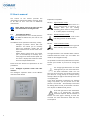
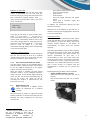
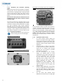
3.1.1
Intelligent 3-position switch with LEDindicator
The intelligent 3-position switch of the HRUC-E
looks like shown below.
The light behind the icon indicates which mode is
activated. With the arrows "up" and "down" the
mode can be changed manually.
It is possible to control the speed of the fan modes.
Contact your installer if you want to change the
speed.
The orange light behind this icon starts
blinking when you turn even lower than
the lower ventilation mode. The unit
than runs at its minimum. This mode can be used if
you leave for a long period, for example during
holidays. When the light is continuously lit the unit
is completely off.
If you want ventilation on-demand, for example
using a CO₂-sensor, you can put the unit in this
position. The unit will automatically increase the
fan setting when the CO₂ concentration increases.
This requires an additional CO₂-sensor.
If the red light next to the exclamation
mark is lit continuously, the filters
should be replaced. See the schedule in
Section 3.2. If the light is blinking, an error has
occurred. For more information about the error,
see chapter 5.
6
3.1.2
Luxury digital operating panel
The Deluxe digital control panel gives you more
options to operate the HRUC-E than the 3-position
switch. This makes it easier to set the unit to your
personal requirements. When you start the unit,
it is not obligated to change the settings if you
do not have the need. There is a default clock
program installed after fabrication. This clock
program turns the unit in mode 1 between 23:00
and 08:30 on weekends and in mode 2
between 8:30 and 23:00. On weekdays, it turns the
unit in mode 1 between 22:00 and 7:30 and the
remaining time in mode 2. How to change the
clock program is explained later in this section. To
find out exactly what your installer can personalize
for you thanks to this digital operating panel, read
section 4.2.3.
When pressing this button you
switch between manual and
automatic mode. The clock
program of the unit only
works when the automatic mode is enabled. In a
menu, you can use this button to move to the next
selectable field.
If you press this button, you
enter the main menu. In a
submenu, you can use this
button to return to the previous menu.
You can use these buttons in
the main menu to select the
submenus. In the submenus
you can change the values
with these buttons.
Pressing this key in a (sub)
menu allows you to confirm
your selection.
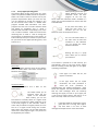
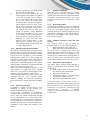
The screen:
The deluxe digital operating panel of the HRUC-E
looks as shown above. The screen contains the
following information:
If no button is pressed for a few seconds, you
automatically return to the main screen. Please
find the meaning of the LED lights on the digital
operating panel below.
If the light is lit under the sun, the
bypass is activated.
The basic buttons:
There are 6 buttons and 3 LEDs on the
conrol panel:
This button allows you to
manually select the fan
speed. If the automatic
mode is enabled ("autom. mode"), you can use
this button to manually switch to a higher mode
but you can not switch to a lower mode than is set
in the clock program. If the automatic mode is
active and you switch to a higher position, the unit
will run in a higher mode during five minutes.
After those five minutes, the unit will follow the
mode of the clock program again. This period can
be adjusted by the installer.
If the light under the ice crystal
illuminates, the frost protection is
active. The frost protection is
activated when the outdoor temperature drops
below zero degrees. The frost protection ensures
that the heat exchanger does not freeze by
reducing the supply air flow. If your supply fan
is not running, always check if this light is on. If
that is the case, it does not concern an error.
If the light below the exclamation mark is
green, the unit is running. If the light is
red, then there is an error or filter
message. See chapter five for more information.
7
Below, the various menus of the deluxe operating
panel will be explained step by step.
once. Press
your settings.
Main menu:
Press
to enter the main menu. The main
menu provides access to the submenus listed
below:
Submenu
Description
1.Operating mode
Operation of the unit
2.Clock program
Set clock program
3.Data time
Set date and time
4.Filter reset
Resetten filter timer
5.Special function
Settings for installer
Submenu 2 - Clock program
The control panel has a seven-day clock program.
The clock program is set as follows:
1. Select the menu clock program in the main
menu and press
.
2. The clock program for Sunday appears, an
example is shown below. You can select the
various fields in this menu, with
.
Use the buttons
menu. Then use the
menu.
and
to select a subbutton to enter the
Submenu 1 - Operating mode
In this menu you can choose the operating mode
of the unit. You can choose from the four options
described below.
1. Holiday speed
Use this mode when you are away for a longer
period. It will only assure minimal ventilation.
Never enable this mode when somebody is
in the house.
2. Winter
This mode is automatically enabled at the
transition to winter time. The bypass can not be
opened now and the air always goes through the
heat exchanger.
3. Summer
This mode is automatically enabled at the
transition to summer time. The bypass can now
open if the conditions mentioned in section 4.2.3
are met. It is therefore important that you indicate
the desired temperature in the summer to your
installer. This desired temperature does not affect
the operation of the HRUC-E in the winter mode.
4. Summer exitair only
In this mode only the exhaust fan works, so the
contaminated air is removed from the home. You
do not get fresh air in your home through the
ventilation system and your supply air is not
filtered! Use this mode only if you want to
ventilate through enough open windows and/or
doors. In this mode there is no heat recovery.
Press
to activate a mode, after you have
selected it with
. The selected mode will blink
8
to exit the submenu and save
3. If you have selected the field that you want to
adjust, use the buttons
and
to change
the value. The program offers six time
intervals. For each time interval you can choose
a ventilation mode (LS). You can choose from
the three modes and the holiday (0) position.
Outside the preset time intervals, the unit will
turn in position two.
4. As soon as the clock program is set for one day
and you press
after the last field (LS
Interval f ), the following line appears at the top
of the screen:
Copy [present] day> [next] day
If you press
, the program of the present
day will be copied to the next day. If you want
to set another program for the following day,
press
.
5. Press
to exit the menu and save your
settings.
Submenu 3 - Data Time
In this menu you can set the current time and date.
This is important for proper functioning of the
program and switching between summer and
winter time. Once you have selected the submenu
from the main menu press
. You will see the
start screen and the hour of the time display
flashes. Press
to change the value. Then go to
the minutes by pressing
. Repeat the
previous steps for the day of the week and the
date. Finish with
or cycle trough all fields to
save the changes.
Submenu 4 - Filter reset
In this menu you can reset the filter timer after
service is effectuated. You can also reset the
timer this way if you change the filters before the
filter maintenance message appears. Press
when you have selected Filter reset in the main
menu. You will see:
If you do not not want to reset the filter time,
press
. If you press
, you will see a
count- down timer from 10 to 00. After this, the
control panel automatically switches back to the
main menu, the light stays on. Finish the action by
leaving the main menu by pressing
. Your filter
timer is reset. 12 weeks later, the filter
maintenance message will be shown automatically
on the control panel again.
Submenu 5 - Special function
In this menu it is possible to personalize settings of
the unit. This can only be done by a qualified
installer. Read section 4.2.3 if you want to know
what your installer can personalize for you.
3.1.3
Extra control option: bathroom switch
The two control panels can be extended with a
bathroom switch. A bathroom switch can be added
to turn the HRUC-E temporarily in the highest
position to extract moist air quicker.
When this switch is activated, the light behind
ventilation mode 3, on the intelligent 3-position
switch, will blink. At the deluxe digital operating
panel, you will see the text "Ventilation Step III
ext" on the screen. This mode can not be
cancelled; the duration is determined by the
timer (see par. 4.2.3).
3.2
-
Check the fins of the heat exchanger.
Clean the heat exchanger
Clean the fans
Clean the drain
Check the speed controller and bypass
system
Check (and if necessary repair) the
electrical wiring.
In addition, we recommend cleaning the duct
system every 6 years.
Maintenance of the HRUC-E by the end user is
limited to cleaning and changing filters. See Annex
I, for more information.
Replacing the filters
The unit will indicate automatically after twelve
weeks that the filters must be replaced. However,
the frequency in which the filters need to be
cleaned, actually depend on the degree of
contamination, so please check this yourself
regularly.
After starting the HRUC-E check the filters regularly
and if necessary replace or clean them. It is advised
to replace your filters every three months. For
optimal performance of your unit, it is
recommended to clean your filters every two
weeks. If you are living in a home that is just build,
it is advisable to clean or replace the filters more
frequently. This is needed because there is a lot of
dust in these houses. If it appears that the
contamination is limited, you can increase the
interval.
Replacing/cleaning the filters is done as follows:
Unplug the HRUC-E before you start!
Open the front cover using the two clips at
the top.
Pull the two filters from the unit, as shown
below.
Maintenance by user
Major maintenance of HRUC-E should
always be performed by a qualified
installer.
We recommend, as shown on page 133 of ISSO
1
Kleintje Ventilation to commit every two years the
following the major maintenance on your heat
recovery unit:
1
Hofman, Ing M.C., & Roijen, Ing. E.J.A., &
Vos, F.A., & Weelde, Ir. A.M. Van, &
Zieremans, H., & Wagenaar, Ir E.J. (2009).
Kleintje
Ventilatie
–
Woningen
en
woongebouwen. Rotterdam: Stichting ISSO
9
-
-
Clean the filters with a vacuum cleaner if they
do not have to be replaced yet.
Slide the new/cleaned filter back in the unit.
There is no difference between the supply air
and exhaust air filter. If an arrow is shown on
the filter, it has to point towards the heat
exchanger.
Close the front cover using the two clips at
the top.
Reconnect the HRUC-E.
Reset the filter timer
The filter time can be reset with the 3-position
control panel and with the digital deluxe operating
panel.
3-position control panel:
Reset the filter time by pressing the two
arrows simultaneously, for over 10 seconds.
The red light will go out.
Luxe digitaal bedientableau:
Press
. Go to Filter reset with
and
press
. Press
again and wait for 10
seconds. Finally, press
to return to the
home screen without notice. As long as the
last action has not been completed, the red
light keeps blinking.
10
3.3
Recycling of the HRUC-E
If your HRUC-E has come at the end of its lifetime,
do not dispose it in your household trash. Consult
with your supplier what he can do with the unit. If
he can not take the unit back, ask your municipality
what you can do. Your municipality has solutions
for the recycling of components or environment
friendly processing of the materials. The HRUC-E is
mainly made of metal and is therefore particularly
suitable for recycling.
IV
Installers manual
This section of the manual provides the
information needed to install, program and
maintain the HRUC-E unit correctly. Information
about errors and reports can be found in chapter
five. Put your contact details on the back of this
manual, after installation.
-
-
-
Always
follow
the
following
requirements at the installation:
The installation, programming and
maintenance of the HRUC-E always has to
be done by an authorized maintenance
technician, unless it concerns small
maintenance what can be done by the
user and is indicated in this manual as
such.
During installation, one needs to observe
the applicable general and local building,
safety and installation regulations of the
city, utilities and other agencies.
There should be no modifications to
the HRUC-E.
4.1 Installation of the HRUC-E
There are four types of the HRUC-E. Unique to
these models is that they can be used both left and
right. It is possible to choose the mounting
configuration on site. The standard setup is the
recommended setup for maintenance. If you want
to switch the configuration follow these steps:
Remove the four M8 nut caps together with
the four rings.
Remove the four rubber caps from the threads
on the other side.
Exchange the brackets of the side and place
back the rings, the cap nuts and the rubber
caps.
Check whether the brackets are attached
correctly and whether its positions are correct.
Remove both covers which are fixed by the
clip closures.
Place both covers back on the unit whilst
making sure the lid with the Comair-HRUC-E
sticker is on the visible side.
4.1.1
Mounting of the HRUC-E
Always install the HRUC-E on a stone wall, in a
frost free area (preferably heated) with a
maximum relative humidity of 80%, to avoid
condensation on and around the unit. Place the
unit as far away from bedrooms as possible, to
avoid noise complaints.
Follow the next steps carefully:
1.
Fix the bracket horizontal (level) on the
wall with the supplied screws and plugs.
Make sure there is enough space to
place a siphon, and possible air silencers
and air distribution boxes. Also make sure
that there is at least 80 cm free space at
the front of the unit. This space is needed
for maintenance.
2.
Hang the unit on the wall bracket using
the mounting brackets that are attached
to the unit. Thanks to these removable
mounting brackets you can choose on the
spot if you hang the unit on the right or
left side.
3.
Level the unit using the adjusting bolts
at the bottom. This ensures a proper
disposal of the condensation.
.
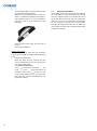
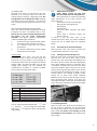
4.1.2
1.
2.
3.
4.
Drain connection
A condensation nozzle is supplied with
this unit. This shoud be fixed under the
unit for the condensation drain.
Slide the duct over the nozzle and create a
siphon, so that a siphon with a minimum
water seal of 65mm is created, like the
image below. Another possibility is an
airtight connection of the duct to a
siphon.
Make sure that the end of the pipe or duct
ends at least 65mm below water level.
Make sure the water seal within the
connection to the sewer is always filled
with water to prevent sewer odor in the
ventilation system.
11
4.1.3
Installation and connection operating
panel
Both control panels can be mounted on a standard
mounting box. For this, seperate the the mounting
frame from the operating panel, screw the frame
into the mounting box, attach the cable as shown
below and click the operating panel back on the
frame.
Note that the panel must be mounted in an area
between 10°C and 30°C with a maximum relative
humidity of 80%.
You have to connect the operating panels on the
unit by means of a cable 4x0,5mm² with flexible
conductors. Ventilair Group Nederland can supply
the right (numbered) cable (article reference
0620166). Connect the numbers of the connection
on the unit with the corresponding numbers on the
operating panel. Ventilair Group Nederland can
also supply a protection cap for the cable on the
unit (article reference 0540131).
Make sure the wires are not mixed up or
short-circuiting, this can cause damage!
Connection on the back side of the intelligent 3position switch
At the 3-position switch connector only number 1
is shown. The three connections next to it are 2, 3
and 4. To the left of the connector is a jumper
which has two possibilities: holiday speed (a) and
off (b). We strongly recommend not to change the
setting. Moving the jumper to position b means
the unit has no holiday speed, in stead it will be
switched off.
Connection on top of the unit
4.1.4
1.
2.
Connection on the back of the digital deluxe
operating panel
3.
4.
5.
12
Connection of the air ducts
In a heat recovery system, always use
silencers and pipes of the right diameter
to keep the air resistance and noise as low
as possible. For advice on the correct pipe
diameter, please contact Ventilair Group
Nederland.
Install the pipes as shown on the sticker
on top of the unit, or look in section 6.3.
Install the air exhaust pipe draining
towards the unit because of possible
condensation in the pipe.
For the connections to the outside,
always use isolated pipes to avoid
condensation in the pipes. Place the inlet
of fresh air preferably on the shady side
of the house; this way you avoid
extremely hot air supply in the summer.
Note also that the inlet of fresh air is
placed sufficiently far from a flue,
according to local standards. Also,
consider compound boundary rules. And
make sure that no rain or animals can
enter the pipes.
Ventilair Group Nederland recommends
to use a straight pipe of at least 40 cm, on
the side of the supply air, before using a
bend. This way, the supply fan performs
optimally.
For the home side Ventilair Group
Nederland recommends you to apply rigid
6.
7.
silencers (acoustically insulated flexible
ducts are not recommended).
You can connect pipes both on the top
and/or bottom of the HRUC-E. If you want
to use the connections on the bottom,
you can remove the spouts on top and the
lids on the bottom, by turning them
counterclockwise. Then you exchange the
spouts and the lids and fix them on the
unit by turning clockwise. If you want to
use both top and bottom connections for
the same air flow, you can order extra
spouts at Ventilair Group Nederland
(article reference 1440071). In this case,
it is necessary to place a control valve to
set the air flow rates per floor and room.
Preferably use pipes that retain their
shape to avoid sagging. When a pipe
sags, moisture can build up, which can
cause damage. Moreover, the airflow can
no longer be guaranteed.
4.1.5 Mounting a ground heat exchanger
The addition of a ground heat exchanger in your
system is optional. If you choose to place a ground
heat exchanger, the preheater is no longer needed.
The ground heat exchanger is not electrically
connected to the HRUC-E. It is wise to adjust the
flow control in terms of percentage, after installing
a ground heat exchanger. This is necessary to
overcome the additional resistance of the ground
heat exchanger. Clarifications on adjusting the flow
control can be found in section 4.2.3.
When a ground heat exchanger is applied, it is not
recommended to engage the mode ‘Summer
exitair only’. The ground heat exchanger has the
ability to cool the incoming air in the summer.
Ventilair Group Nederland provides a ground heat
exchanger under the name Aquacom (Article
reference 1230601). The Aquacom is designed to
perform optimally in combination with the HRUCE.
4.1.6
Explanation preheater
A preheater is added to some units, for frost
protection, in addition to the standard frost
protection that works with imbalance.
If one chooses a preheater, and a difference
between supply and exhaust air of more than 4°C
occurs when the outdoor temperature is below
0°C, the preheater turns on for 30 minutes. After
30 minutes there is a check whether the difference
has narrowed. If this is not the case, the process is
restarted. The preheater is installed at the factory.
Installation is not possible after delivery of the
HRUC-E.
4.2
Settings of the HRUC-E
Once the unit is mounted and the selected
operating panel is connected, the HRUC-E can be
started. Check again that all air pipes and electrical
connections are connected properly. Then insert
the plug into the socket. The unit will start in a few
seconds.
4.2.1
General information
The control of the HRUC-E consists of an integrated
control board and a operating panel. As operating
panel you can choose between digital deluxe
operating panel or the 3-position switch. Any error
messages are displayed on the operating panel.
Both panels are plug&play: after a brief self-test,
they can control the unit.
4.2.2
Intelligent 3-position switch with LEDindicator
The 3-position switch is used to control the
ventilation system. It has the following features:
1.
Manual activation of the modes 1 to 3
2.
Reset of the filter time (see Section 3.2)
If it is necessary to adapt the air volume per
position during the setting of the system, or if the
bypass temperature has to be changed, you can
temporary use a digital deluxe operating panel. If
this is not necessary, the 3-position switch can be
connected immediately and the unit can be used.
4.2.3
Digital deluxe operating panel
The Deluxe digital operating panel provides, in
addition to the features of the 3-position switch,
the following:
3. Clock program with six switching points
per day for each day of the week.
4. Intelligent control bypass.
5. Temperature display in the room where
the operating panel is mounted.
6. Adjustment of the ventilation modes.
In the next section of the manual, there is a
clarification of the submenu five ‘Special function’
from the main menu. For the first four submenus,
see Section 3.1.2. Select the submenu from the
main menu with
and press
. The fifth
submenu is only visible when you pass submenu
4: Filter reset.
13
Submenu 5 - Special function
This menu is only intended for qualified installers.
This menu requires a code. Contact your dealer
to obtain this code. Use
to c hange a
number. Use
to skip to the next number.
In the menu ‘Special function’, you have the
following choices:
RHL3VZ
This field allows you to set the delay of the
unit. This setting determines how long it takes
for the unit to respond to an external control
switch such as the bathroom. This field is set
with
and with
. Note: unlike the other
values in this menu, this field in minutes.
Submenu
5.1 Operating
hours
5.2 System
settings
5.3 Fan config
5.2 System settings
This is the menu where the system parameters can
be set, which make the unit work properly. These
settings are only for the installer, to avoid
settings that can lead to damage. As you enter
this menu you will see the following screen:
Description
Here you can find the working
hours per function
Here you can change the settings
(language, wanted temp.)
Here you can set the air flows in
terms of percentage
Use
and
to select a menu. After
selecting the right menu, you can enter the
menu with
.
5.1 Operating hours
In this menu you can see how long and in what
position the unit has been turning. You can also
set the duration of position 3 in this menu. Note:
This information is stored in the operating panel,
not in the unit. A new operating panel will display
no operating hours.
In this menu you can find the following details:
Display
Description
L1/2/3
Ventilation position 1/2/3
L4
Frost protection
B
Bypass open
LG
Total running hours
In this menu you can select three fields with
The possibilities for each field are described
below.
LG
If you press
, when you have selected this field,
you will reset all counters to zero.
L3TON
This field allows to set the duration of the timer of
the unit. This setting determines how long the unit
remains in the highest position after a signal from
an external control such as a bathroom switch (par
3.1.3). It also determines the duration of a manual
switch to a higher ventilation position, when the
unit is in the automatic mode. You can change the
value of this field with
and
. Note: u nlike
the other values in this menu, this field is
expressed in minutes.
14
In this menu you can swith between the adaptable
fields with
. All fields are explained here
below. The values in the fields can be changed with
and
.
Wanted temp.
In this field you can enter the wanted temperature.
This temperature has only effect on the operation
of the bypass. So you have to set the desired
indoor temperature in the summer.
Reset
This field allows you to reset the operating panel to
factory settings. To reset the panel, you have to
enter the value 55 in this field. Then go through
the menu until the wanted temp. is blinking. Then
press and hold
. To reset, press
too
and release this button to complete the process.
Adjust, correction of the temperature of the room.
To ensure that the operating panel displays the
same temperature as a thermostat in the same
room, it is possible to correct this value here.
English, setting of the language
In this field you can select the language of the
operating panel. There are five options: German,
English, French, Dutch and Polish.
CO2, the presence of a CO2-sensor
As soon as the CO2-sensor is connected and
detected properly, a 1 will appear instead of a 0.
rV, holiday mode
By filling in the value 1 in this field, the unit can
ventilate at its minimum when you select the
holiday speed in submenu 1 Operating mode. We
strongly advise not to change this value! Changing
this value to zero means that the unit does not
have a holiday speed anymore and will turn off in
stead.
Byp, the outside temperature for the bypass
This is the minimal outside temperature at which
the bypass can open. The default value is 17°C.
Note: if you set a too low outside temperature for
the bypass, you can create condensation
problems. The bypass operates automatically
under the following four conditions:
1.
It must be summer (summer mode active).
2.
It should be colder outside than inside.
3.
It is warmer inside than the desired
temperature.
4.
It is warmer outside than the set outside
temperature for the bypass.
5.3 Fan Config
As you enter this menu, you will see the
percentage of the air flows, for both supply and
exhaust air, for each position. The percentage of
the holiday mode cannot be changed. The default
setting is 20%, the lowest possible. If you do not
change these settings, the unit provides the
quantities that are shown in section 6.2. Below
you can find an example of the menu:
The following applies:
Position Description
L1 sup
Percentage supply fan position 1
L2 sup
Percentage supply fan position 2
L3 sup
Percentage supply fan position 3
L1 exh
Percentage exhaust fan position 1
L2 exh
Percentage exhaust fan position 2
L3 exh
Percentage exhaust fan position 3
You can choose the desired field with
. with
and with
you can change the percentages
Then press
to leave the menu and apply the
new settings.
4.3
Maintenance by installer
NOTE: Always remove the plug from
the wall socket before servicing the unit!
We recommend to commit the following
major maintenance of the heat recovery unit
every two years:
Check the fins of the heat exchanger;
Cleaning heat exchanger block;
Cleaning fans;
Cleaning drain;
Check the speed controller and bypass
system;
Check (and if necessary repair) the
electrical wiring.
In Annex II, you can keep track of the
maintenance that is done. The actions needed to
service the unit as stated above are explained
below.
4.3.1
Check the fins of the heat exchanger
Open the front cover. Then check if the fins are
not bent and/or the seams are not open.
4.3.2
Cleaning the heat exchanger core
Open the front cover and remove the exchanger
from the unit. This can be done using a set of
suction cups. Then remove the dust between the
fins with a vacuum cleaner and brush. Wipe gently
with a brush between the fins. If necessary, dip it
in lukewarm sopwater the heat and rinse them
with clean lukewarm water. As you do, do not use
harsh or dissolving cleaning products. Then remove
the water from the exchanger, by lifting it on the
smooth exterior and shaking it gently. Finally,
replace the six foam seals (article reference
0450153) at the corners of the exchanger and rub
them abundantly with vaseline. Then place the
exchanger back with a metal plate to avoid damage
to the seals at the moment you slide the exchanger
in the unit (see picture).
4.3.3 Cleaning the fans
Open the front cover. Slide the fan towards you.
Do not remove it, otherwise you will disconnect
the wiring. Clean the fan using a vacuum cleaner
with a brush. Be careful not to damage or move
the weights on the fan blades! Then slide the fan
back in again.
15
4.3.4 Cleaning the drain
Remove the duct from the condensate drain and
clean it. Make sure you put the siphon in place
again according to the requirements specified in
section 4.1.2. To avoid dehydration you can poor a
little bit olive oil into the condensate drain.
4.3.5 Check the speed controller and bypass
system
Please note that this control should be done when
the unit is working. Stay away from moving parts
and watch out for power lines!
To test the speed controller, turn the unit in the
three positions and check if the unit accelerates
and decelerates properly. To verify that the bypass
control is working, you must open the front cover
and then warm the sensor ‘T2 extraction from
habitat’ by holding it in your hand. The
temperature ‘T3 supply from outside’ must be at
least 17°C (factory setting) and not higher than T2.
The bypass will respond after one minute.
4.3.6 Check (and if necessary repair) the
cal wiring.
Check the wiring and make sure that no
touching a fan. If a cable is damaged,
contact Ventilair Group Nederland to
solution.
16
electriwire is
please
find a
V
Errors
5.1
Errors intelligent 3-position switch with
LED indicator
On the 3-position switch, errors are indicated by a
flashing light behind
. Which error has occurred
depends on the flash. Here below, you can see
what action you should take to resolve the error.
This manual is for both users and installers, so this
table is too. The end user can see in the column
‘action’ the appropriate action to do. The installer
can see in the column scheme , where he can find
the correct scheme to resolve the problem. These
solutions schemes are only intended for installers.
The message is displayed until the cause has been
corrected.
5.2 Errors deluxe digital operating panel
On the Deluxe digital operating, errors are noted
by a blinking light under .
The error is shown on the screen with text. The
following table shows what action you should take
to resolve the error. This manual is for both
users and installers, so this table is too. The end
user can see in the column ‘action’ the appropriate
action to do. The installer can see in the column
‘ scheme’, where he can find the correct scheme to
resolve the problem. These solutions schemes are
only intended for installers. The message is
displayed until the cause has been corrected.
Some remarks only intended for the installer;
do not effectuate these if you are the end user:
If only the supply fan stopped but the operating
panel does not display an error, it is possible that it
is the frost protection. This does not appear in the
3-position switch. Please note that the next
control should be done when the unit is working.
Stay away from moving parts and watch out for
power lines! To check whether this is indeed the
case, you need to warm temperature sensor T3
(see section 6.4 for location) above freezing point
by holding it in your hand. If there is no error, the
supply fan will start again. If an error does not
match the described characteristics, follow the
scheme 5.3.1.
Some remarks only intended for the installer,
do not effectuate these if you are the end user:
If an error does not match the described characteristics, follow the scheme 5.3.1.
Above each error message, you will see ‘ CPU
adres adr1’. Deze regel geeft aan welk apparaat
een storing heeft gemeld. Dit wijkt enkel af als u
meerdere toestellen heeft aangesloten op één
bediening. This line indicates which unit has
reported an error. This differs only on when you
have multiple units connected to one control
panel.
17
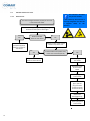
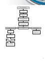
5.3
Solution schemes for errors
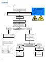
5.3.1
General error
This scheme is intended
only for the installer.
Maintenance by the end user is
not only dangerous but also has
a negative effect on the
warranty.
The unit no longer functions properly or the error
is not listed in the table.
Reset the unit by pulling out the plug during 10
seconds and then place it back again
Yes
Wait 15 minutes.
Does the unit work?
No
Open the cover of the control
board on top of the unit
The error is
(temporarily) fixed,
keep an eye out for
new errors
Yes
Replace the control
panel or control board
Is there 230V on the power entry
of the control board? (N & L1)
No
Pull the plug out of
the socket
Replace the fuse
at the control
board
Put the plug back
in the socket
If the fuse breaks
again, pull the
plug out of the
socket and check
all internal wiring
Replace the
damaged wiring
Put the plug back
in the socket
18
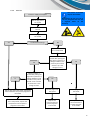
5.3.2
Fan error
This scheme is intended
only for the installer.
Extract or supply fan stopped
Maintenance by the end user is
not only dangerous but also has
a negative effect on the
warranty.
Pull the plug out of
the socket
Open the front lid of
the unit
Put the plug back in
the socket
Are both fans turning?
Yes
No
Open the cover of
the control board
No
Ja
Measure (within 1
minute after putting the
plug back in) if there is a
voltage between 0 and
10 volts on the poles 0
and U1 or U2 as shown
in section 6.5. Is the
voltage correct?
Measure (within 1
minute after putting the
plug back in) if there is a
voltage of 230V on the
poles K1 (see scheme
section 6.3). Is the
voltage correct?
No
No
Pull the plug out of the socket, replace the
cables of the fans and put the plug back in
the socket
Pull the plug out of
the socket
Pull the plug out of
the socket
If this does not work or when
this is not possible, replace the
complete fan set and put the
plug back in the socket
Replace the
control board and
put the plug back
in the socket
Replace the
control board and
put the plug back
in the socket
19
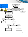
5.3.3 Sensor error
This scheme is intended
only for the installer.
Open line or short circuit on sensor
(T1, T2, T3, T4)
To determine which sensor is creating an error, you can connect a
digital control panel deluxe temporarily to units with a 3-position switch
Maintenance by the end user is
not only dangerous but also has
a negative effect on the
warranty.
Pull the plug out of
the socket
Open the front lid of the unit and
the cover of the control board
Check the cable of the relevant
sensor for an open line error
Yes
Is the cable broken?
Place a new sensor or repair
the cable and put the plug
back in the socket
Exchange temporarily
the wires of the sensor
with those of another
sensor on the control
board and restart the
unit
Optionally, you can measure the
resistance of the sensor. It
should comply with the following
table:
Yes
Temp. [˚C]
-20
-10
0
10
20
25
30
20
R [Ω]
684
747
815
886
961
1000
1040
No
Does the error indicate
another sensor now?
No
Pull the plug out of
the socket
Pull the plug out of
the socket
Place a new
sensor in the right
place and put the
plug back in the
socket
Replace the
control board and
put the plug back
in the socket
5.3.4 Error cabling/ data transfer
This scheme is intended
only for the installer.
Error data transfer
Maintenance by the end user is
not only dangerous but also has
a negative effect on the
warranty.
Pull the plug out of
the socket
Check if 1,2,3 and 4 are connected
correctly from the unit to the
control panel (same color of the
wires for each number)
Yes
No
aangesloten
Make sure the cable is well
plugged in, there is no shortcircuit and it is not broken on
the inside
Connect like in section 6.5
and put the plug back in
the socket
It is also possible to connect a
short cable to exclude errors
in the cable
Yes
Problems with cable?
Replace the cable
and put the plug
back in the socket
No
Open the cover of the
control board and put the
cable of the control panel
directly in the control
board
Yes
Repair the wiring between
the cover and the control
board and put the plug back
in the socket
Does it work now?
No
Replace the control panel
and/or control board and
put the plug back in the
socket
21
VI
Specifications HRUC-E
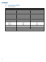
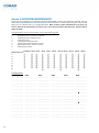
6.1
Technical specifications
HRUC-E2
HRUC-E3
Air specifications
Air flow
Filter classification
Bypass
300m³/hour (@150Pa)
G4 (optional F5)
100%
380m³/hour (@150Pa)
G4 (optional F5)
100%
Mechanical specifications
Dimensions(hxwxd)
Weight
Connections
Heat exchanger
710x842x506mm
55kg
Ø180mm 4x top, 2x bottom
Aluminium, counterflow
710x842x506mm
55kg
Ø180mm 4x top, 2x bottom
Aluminium, counterflow
Electrical specifications
Electrical connection
Fans
Power input
position 1
position 2
position 3
Max. current
Cos Phi
Fuse
Control
Optional control
22
230V AC +/- 10%; 50Hz
EC-motor (EBM)
14W
28W
98W
0,86A
230V AC +/- 10%; 50Hz
EC-motor (EBM)
18W
36W
129W
1,13A
0,49
0,49
2A slow
2A slow
3 – position switch and deluxe digital control panel
Bathroom switch
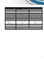
HRUC–E4
HRUC–E5
Air specifications
Air flow
Filter classification
Bypass
450m³/hour (@150Pa)
G4 (optional F5)
100%
520³/hour (@150Pa)
G4 (optional F5)
100%
Mechanical specifications
Dimensions(hxwxd)
Weight
Connections
Heat exchanger
710x842x506mm
55kg
Ø180mm 4x top, 2x bottom
Aluminium, counterflow
710x842x506mm
55kg
Ø180mm 4x top, 2x bottom
Aluminium, counterflow
Electrical specifications
Electrical connection
Fans
Power input
position 1
position 2
position 3
Max. current
Cos Phi
Fuse
Control
Optional control
230V AC +/- 10%; 50Hz
EC-motor (EBM)
12W
38W
172W
1,35A
230V AC +/- 10%; 50Hz
EC-motor (EBM)
14W
47W
225W
1,76A
0,55
0,55
2A slow
2A slow
3 – position switch and deluxe digital control panel
Bathroom switch
23
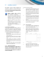
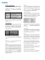
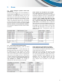
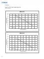
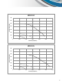
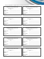
6.2 Air flows
The graphs below show the air flow each of the
HRUC-E units can move plotted against the
external resistance.
HRUC-E2
400
350
Pressure drop [Pa]
300
250
200
150
100
50
0
0
50
100
150
200
250
300
350
400
450
Air flow [m3/hour]
HRUC-E3
700
600
Pressure drop [Pa]
500
400
300
200
100
0
0
50
100
150
200
250
300
Air flow [m3/hour]
24
350
400
450
500
HRUC-E4
700
600
Pressure drop [Pa]
500
400
300
200
100
0
0
100
200
300
400
500
600
400
500
600
Air flow [m3/hour]
HRUC-E5
700
Pressure drop [Pa]
600
500
400
300
200
100
0
0
100
200
300
Air flow [m3/hour]
25
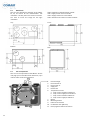
6.3
Dimensions
Here are the dimensional drawings of the HRUCE2, E3, E4 and E5 for the recommended left
installation. This way the unit is easier to maintain.
You have to mirror the image for the right
installation.
ANB = Projection of the polluted air outside
TVB = Supply of fresh air from outside
TNW = Supply of fresh air to the habitat
AVW = Extraction from the air out of the habitat
Top:
Front:
Bottom:
Side:
6.4
List of components
Here is a list of components of the HRUC-E. On the
next page you can find the article references, if you
need to order one of the components.
1.
2.
3.
4.
5.
6.
11
26
Heat exchanger
Filter exhaust air
Filter supply air
Supply fan
Exhaust fan
Temperature sensors
a. Temp. sensor projection outside T4
b. Temp. sensor supply from outside T3
c. Temp. sensor extraction habitat T2
d. Temp. sensor supply to habitat T1
7. Bypass
8. Mounting bracket
9. Electrical connections
10. Condensate drain (Ø17mm)
11. Extra spigot for bottom connection
Number
Component
Ond Heat exchanger
1
erdeel
2+3
Filter set G4
2+3
Filter set F5 (pollen filter)
4+5
Fan with housing
6
Temperature sensor
Arti Bypass motor with cable
7
kelnummer
9
Controller HRUC-E
1
10
Tailpiece for condensate drain
War Extra spigot for bottom connection
11
mtewisselaa
Deluxe digital control panel
r3- position switch with LED
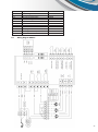
6.5
Article reference
0820030
0130003
0130004
On demand
1146050
0320092
On demand
1230684
1440071
2070025
2070026
Wiring
082 diagram HRUC-E
0030
2+3
Filte
rset G4
013
0003
2+3
Filte
rset
F5
(fijnstoffilter
)
013
0004
4+5
tilator
huis
Ven
incl.
Op
aanvraag
6
Tem
peratuurvoel
er
114
6050
7
ass
incl.
Byp
motor
kabel
032
0092
9
Reg
eling HRUC-E
Op
aanvraag
27
Annex I MAINTENANCE BY USER
This annex provides you, as a user, information about the maintenance of your unit. To make it complete, you
can also find the cleaning instruction for the valves. Although this is not part of the HRUC-E, a clean valve
provides an optimum air flow. After the instruction, you can find the maintenance instructions for the filters of
your HRUC-E.
Cleaning the valves
The supply and exhaust valves in your home should be cleaned (at least) twice a year.
Note: Do not change the settings of the valves! These settings have been carefully set by the installer and
any change affects the functioning of the ventilation system.
The cleaning is done as follows:
Remove the valve from the ceiling or wall.
Clean the valve in a solution of warm water and soap.
Rinse the valve and then dry it thoroughly.
Place the valve back at the same place and at the same position.
Cleaning/changing the filters
Note: Follow the steps in Section 3.2 or the scheme on the next page carefully when you clean or change The
filters. If you effectuate the maintenance in another way, the warranty will be no longer valid.
Advice for checking/cleaning/changing the filters:
Check the filters before starting up the unit.
Change the filters every month or two in the first six months.
After that, change them every three months (as the filter timer automatically specifies).
You can keep track of the dates of changing the filters on page 32.
Get one filter set for your HRUC-E for free!
It is very important to regularly check your filters for dust accumulation,
rinse the them/or change them. To make this process easier for you here is a
one time offer for a free G4 filter set. The only thing you have to do is send an
email to [email protected] containing the follow information:
Subject of your email:
Include in your email:
Free filter set HRUC-E
- The Serial Nr. of your unit (see sticker on the side of the unit).
- The details of the installer from whom you’ve purchased the unit.
- Your name and mailing adress, so we can send the filters.
28
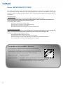
Error: Exchange filter
.
Pull the plug out of
the socket
Open the front lid of
the unit
Change the filters (note: the
arrow on the filter has to
point towards the bottom)
Put the front lid back on
the unit and put the plug
back in the socket
Deluxe digital control panel
Press
Which control panel do you
have?
3-position switch
Press both arrows
simultaneously
during 10 seconds
Select the filter reset
menu with and press
Press
again and
wait 10 sec.
Press
to return to
the main screen
without error message
29
Annex II OVERVIEW MAINTENANCE
Please fill in here below the maintenance activities effectuated on the unit to keep the overview. The first
table shows what maintenance should be done en what maintenance is performed in the past. In the second
table, you can indicate when you changed the filters. Note: If there is major maintenance to be done, you
have to observe the requirements of section 2.6, 3.2 and 4.3 at all times, otherwise your warranty will no
longer be valid!
The maintenance actions for the installer consist of the following parts:
1.
Changing filters
2.
Straighten the fins of the heat exchanger
3.
Cleaning the heat exchanger block
4.
Cleaning the fans
5.
Cleaning the condensate drain
6.
Checking the speed and bypass control
7.
Repairing damage to electrical wiring
8.
Cleaning duct system
Installation +2year +4year +6year +8year +10year +12year +14year +16year +18year +20year
Maintenance task
1.
2.
3.
4.
5.
6.
7.
8.
Changing filters
Date
Date
Date
Date
Date
Date
......................... ......................... ......................... ........................ ........................ .........................
......................... ......................... ......................... ........................ ........................ .........................
......................... ......................... ......................... ........................ ........................ .........................
......................... ......................... ......................... ........................ ........................ .........................
......................... ......................... ......................... ........................ ........................ .........................
......................... ......................... ......................... ........................ ........................ .........................
......................... ......................... ......................... ........................ ........................ .........................
......................... ......................... ......................... ........................ ........................ .........................
......................... ......................... ......................... ........................ ........................ .........................
......................... ......................... ......................... ........................ ........................ .........................
......................... ......................... ......................... ........................ ........................ .........................
......................... ......................... ......................... ........................ ........................ .........................
......................... ......................... ......................... ........................ ........................ .........................
......................... ......................... ......................... ........................ ........................ .........................
30
Place your information or stamp here below at each inspection and service:
10 Inspection and service after 2 year
Working hours unit: ...................
Date: ..................
Installer name:
Address:
Phone number:
Remarks:
…………………………………………………………
…………………………………………………………
…………………………………………………………
…………………………………………………………
…………………………………………………………
..
Inspection and service after 12 year
Working hours unit: ...................
Date: ..................
Installer name:
Address:
Phone number:
Remarks:
…………………………………………………………
…………………………………………………………
…………………………………………………………
…………………………………………………………
…………………………………………………………
..
Inspection and service after 4 year
Inspection and service after 14 year
Working hours unit: ...................
Date: ..................
Working hours unit: ...................
Date: ..................
Installer name:
Address:
Phone number:
Remarks:
…………………………………………………………
…………………………………………………………
…………………………………………………………
…………………………………………………………
…………………………………………………………
..
Installer name:
Address:
Phone number:
Remarks:
…………………………………………………………
…………………………………………………………
…………………………………………………………
…………………………………………………………
…………………………………………………………
..
Inspection and service after 6 year
Inspection and service after 16 year
Working hours unit: ...................
Date: ..................
Working hours unit: ...................
Date: ..................
Installer name:
Address:
Phone number:
Remarks:
…………………………………………………………
…………………………………………………………
…………………………………………………………
…………………………………………………………
…………………………………………………………
Installer name:
Address:
Phone number:
Remarks:
…………………………………………………………
…………………………………………………………
…………………………………………………………
…………………………………………………………
…………………………………………………………
…………………………………………………………..
..
Inspection and service after 8 year
Inspection and service after 18 year
Working hours unit: ...................
Date: ..................
Working hours unit: ...................
Date: ..................
Installer name:
Address:
Phone number:
Remarks:
…………………………………………………………
…………………………………………………………
…………………………………………………………
…………………………………………………………
…………………………………………………………
Installer name:
Address:
Phone number:
Remarks:
…………………………………………………………
…………………………………………………………
…………………………………………………………
…………………………………………………………
…………………………………………………………
..
..
Inspection and service after 10 year
Inspection and service after 20 year
Working hours unit: ...................
Date: ..................
Working hours unit: ...................
Date: ..................
Installer name:
Address:
Phone number:
Remarks:
…………………………………………………………
…………………………………………………………
…………………………………………………………
…………………………………………………………
…………………………………………………………
..
Installer name:
Address:
Phone number:
Remarks:
…………………………………………………………
…………………………………………………………
…………………………………………………………
…………………………………………………………
…………………………………………………………
..
31
Your HRUC-E installer
Date: ..................
Name installer:
Adress:
Phone number:
Remarks:
Ventilair Group Nederland B.V.
Kerver 16
5521 DB Eersel
The Netherlands
Tel.: +31 (0) 497 - 36 00 31
Fax: +31 (0) 497 - 33 08 93
www.ventilairgroup.com
[email protected]
32
...................................................
...................................................
...................................................
...................................................
...................................................
...................................................