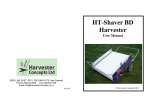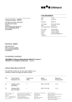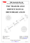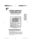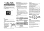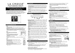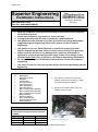
1
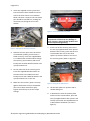
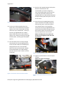
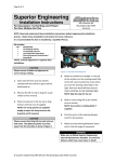
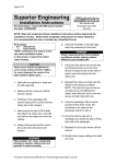
Page 1 of 3
Superior Engineering
Installation Instructions
Part Description: FORD PX RANGER BASH PLATE
AND REOVERY POINT
Part Nos: SUP-RANGUDRGRD
•
•
•
•
•
•
•
•
499 Uhlmann Rd
Burpengary QLD 4505
Australia
WARNING
Read and completely understand these Installation Instructions before beginning
the installation process.
Retain these installation Instructions for future reference.
It is highly recommended this item is installed by a Qualified Person.
This product must be installed as per these instructions only using the hardware
supplied by Superior Engineering unless under written consent of Superior
Engineering.
This product is not to be fitted differently or modified in anyway than what
Superior Engineering specified, without written consent of Superior Engineering.
Always check this product for any damage and to make sure all hardware is
tightened to correct torque settings before using. If there is any damage to this
product DO NOT USE in any circumstance, call Superior Engineering immediately.
Do not make any repair or modification without written consent from Superior
Engineering.
This product is not to be used on any other vehicle than those specified by Superior
Engineering.
Kit Includes:
QTY
1
1
1
1
3
2
2
2
2
3
7
7
2
2
4
DESCRIPTION
Rated Recovery Point
Bash Plate
Threaded Plate
Recovery Point Boss
10mm Thick Spacers
20mm Thick Spacers
40mm Thick Spacers
M10 1.5 x 75mm Dome Head Bolts
M10 1.5 x 50mm Dome Head Bolts
M10 1.5 x 40mm Dome Head Bolts
M10 Flat Washers
M10 Spring Washers
M14 1.5 x 130mm Bolts
M14 Nylock/Conelock Nuts
M14 Flat Washers
1. Start with the vehicle front and rear
wheels chocked and the vehicle in gear
with the hand brake applied.
2. Remove the OE bash plate as per the
vehicle service manual.
CAUTION
Please ensure all bolts are tightened to
correct torque setting with Loctite. Recheck
in 500km.
Size
Torque (Nm) Torque (ft-lb)
M10
49
36
Figure 1: Factory Bash Plate
M12
85
64
M14
135
96
© Superior Engineering 499 Uhlmann Rd Burpengary QLD 4505 Australia
Page 2 of 3
3. Insert the supplied recovery point boss
into the furthest hole towards the driver
side of the front chassis cross member.
NOTE: This boss is tapered. The narrowest
part should be inserted first, making the
narrowest part facing the rear of the
vehicle.
Figure 3: Correctly Fitted Recovery Point
WARNING
Make sure all captive nuts and any
components are free from any damage or
wear. If there is, do not fit this product and
contact Superior Engineering.
Figure 2: Fitting Of The Recovery Point Boss
4. Slide the recovery point over the chassis
crossmember (making sure the boss is
fitted correctly). Insert the supplied M14
1.5 x 130mm bolt and flat washer though
the recovery point and boss and secure
loosely with another M14 flat washer and
nylock/conelock nut.
7. At the rear of the recovery point insert
the two (2) supplied 10mm thick spacers
between the recovery point and the rear
crossmember. Be sure to line these
spacers up with the holes in the rear of
the recovery point. (Refer to figure 4).
5. On the other side of the recovery point
insert the supplied M14 flat washer on
the other M14 1.5 x 130mm bolt and
loosely secure with a M14 flat washer and
nylock/conelock nut on the rear.
6. Make sure the recovery point is hard up
against the bottom of the crossmember
(This can be done with a floor jack).
Tighten the bolts up to correct torque
settings.
Figure 4: Fitting Of The 10mm Spacer
8. Lift the bash plate into position with a
suitable lifting aid.
9. In between the front of the bash plate
and the chassis crossmember, place the
two (2) supplied 20mm thick spacers and
loosely secure with the supplied M10 1.5
x 50mm dome head bolts. (As seen in
figure 5).
© Superior Engineering 499 Uhlmann Rd Burpengary QLD 4505 Australia
Page 3 of 3
12. Place the last supplied 10mm thick spacer
between the bash plate and
crossmember. (As shown in figure 6).
Line the threaded plate up with the hole
in the bash plate then loosely fit the
supplied M10 1.5 x 40mm dome head bolt
though the bash plate and spacer into the
nut on a wire.
Figure 5: Correct Fitting Of The Front Spacers
10. At the rear of the bash plate there are
three holes, two of the holes line up with
captive nuts in the crossmember and the
other lines up to a blank hole. Loosely fit
the two (2) supplied M10 1.5 x 40mm
dome head bolts into the holes with the
captive nuts, making sure they go through
the bash plate, recovery point and 10mm
spacers.
11. The third hole (closest to the passenger
side) needs to use the threaded plate to
secure the bolt. Slide the threaded plate
though the hole in the crossmember
above the hole in the bash plate. (NOTE:
the threaded plate may need bending.
The best way to do this is with a vice and
a hammer).
13. Insert the two (2) supplied 40mm thick
spacers between the middle bash plate
and recovery point. Centre the spacers
over the bolt holes in the bash plate.
Loosely fit the two (2) supplied M10 1.5 x
75mm dome head bolts though the bash
plate, 40mm spacer and recovery point
into the captive nuts in the chassis.
NOTE: The bash plate may need to be
moved around slightly to line the holes
up correctly.
Figure 7: Correctly Fitted Boss Spacer
14. Tighten up all the bolts to correct torque
settings.
NOTE: Use Loctite on all bolts.
Figure 6: Correct Place To Insert The Nut On A Wire
Figure 8: Correctly Fitted Bash Plate And Recovery
Point
© Superior Engineering 499 Uhlmann Rd Burpengary QLD 4505 Australia