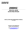
1
CLSM-98a
Tri-Flo CL Series
Centrifugal Pumps
®
Service & Installation Manual
CONTENTS
Thank you for purchasing a Tri-Clover Product!
This manual contains disassembly and assembly instructions, maintenance procedures,
troubleshooting, and a complete parts list for all CL Series Centrifugal Pumps designed and
manufactured by Tri-Clover Inc., Kenosha, Wisconsin.
READ THIS MANUAL carefully to learn how to service these pumps. Failure to do so could
result in personal injury or equipment damage.
SAFETY
DO'S AND DON'TS ........................................................................................................................... 3
IMPORTANT SAFETY INFORMATION ............................................................................................ 4
TECHNICAL INFORMATION
TECHNICAL DATA ............................................................................................................................ 5
INSTALLATION
UNPACKING EQUIPMENT ............................................................................................................... 6
INSTALLATION ................................................................................................................................. 7
OPERATIONAL CHECK ................................................................................................................... 8
MAINTENANCE
CLEANING AND REPAIR ................................................................................................................. 9
MAINTENANCE
DISASSEMBLY ................................................................................................................................. 10
INSPECTION .................................................................................................................................... 15
ASSEMBLY ....................................................................................................................................... 15
TROUBLESHOOTING
TROUBLESHOOTING ...................................................................................................................... 26
PARTS LIST
ORDERING INFORMATION ............................................................................................................. 28
EXPLODED VIEW ............................................................................................................................ 29
CROSS SECTIONAL VIEW .............................................................................................................. 30
CL PUMP REPLACEMENT PARTS .................................................................................................. 32
CL PUMP REPLACEMENT PARTS .................................................................................................. 33
CL PUMP REPLACEMENT PARTS .................................................................................................. 34
CL PUMP REPLACEMENT PARTS .................................................................................................. 35
SEAL REPLACEMENT PARTS - TYPE DG (EXTERNAL BALANCED SEAL) ................................ 36
SEAL REPLACEMENT PARTS - TYPE FG (WATER COOLED SINGLE SEAL) ............................ 37
SEAL REPLACEMENT PARTS - TYPE EG (WATER COOLED, BALANCED DOUBLE SEAL) ..... 38
SEAL REPLACEMENT PARTS - JOHN CRANE DOUBLE 8 SEAL ................................................ 39
-2-
SAFETY
DO'S AND DON'TS
DO read and understand these instructions before installing or using the pump.
DO NOT modify the pump. Modifying the pump creates unsafe conditions and voids all
warranties.
DO use Tri-Clover spare parts when replacing a component of the pump.
DO NOT place the pump in an application where the service ratings are exceeded.
DO NOT service the pump while it is running.
SAFETY PRECAUTIONS WHEN INSTALLING PUMP
DO use an authorized electrician when connecting the pump.
DO observe the mechanical limits of the pump (refer to the pump performance sheet).
DO NOT lift the Motor and Pump by the pump casing or wingnuts.
If it is necessary to regulate flow out of the pump, DO install a throttling valve in the discharge
outlet line. DO NOT install a throttling valve in the suction inlet line.
SAFETY PRECAUTIONS WHEN OPERATING PUMP
DO NOT touch the pump or the lines when pumping hot fluids or when performing Clean In Place
(CIP) procedures.
DO NOT run the pump with BOTH the suction inlet and discharge outlet blocked. Running the
pump with the inlet blocked will cause serious damage to the pump.
DO NOT check pump rotation with liquid in the pump.
DO NOT run the pump with the impeller rotating in the wrong direction. Rotating the impeller in
the wrong direction may cause damage to the pump.
DO NOT operate the pump without the seal guard in place.
SAFETY PRECAUTIONS WHEN SERVICING PUMP
DO ensure the pump is cool to touch before performing service.
DO relieve all pressure and drain all fluids from pump and connected piping before performing
service.
DO ENSURE POWER TO THE UNIT HAS BEEN UNPLUGGED PRIOR TO PERFORMING ANY
PUMP MAINTENANCE OR CLEANING.
DO exercise caution and wear protective clothing when using lye or acid for cleaning.
These instructions contain operating and service information for the pump only. Motor
information is provided separately by the motor manufacturer.
-3-
SAFETY
IMPORTANT SAFETY INFORMATION
The following DANGER, WARNING, AND CAUTION signs and their meanings are used within
these instructions.
! DANGER
Indicates an imminently hazardous situation
which, if not avoided, will result in death or
serious injury. The word Danger is used in
the most extreme cases.
WARNING
Indicates a potentially hazardous situation
which, if not avoided, may result in minor
or moderate injury. May also be used to
alert against an unsafe operating or
maintenance practice.
CAUTION
Indicates a potentially hazardous situation
which, if not avoided, could result in death or
serious injury.
-4-
TECHNICAL INFORMATION
TECHNICAL DATA
SPECIFICATIONS
Maximum Inlet Pressure ........................................................................ 145 PSI (1000 kPa) (10 bar)
Temperature Range............................................................................. 14oF - 284oF (-10oC to 140oC)
Typical Motor Noise Level ............................................................................................. 60 - 80 dB(A)
MATERIALS
Product Wetted Steel Parts ................................................................................................ AISI 316L
Product Wetted Seals ............................................................................................. EPDM (standard)
Alternative Seals.............. BUNA-N, SFY (Fluoroelastomer), PTFE Encapsulated Fluoroelastomer
Finish ..................................................................................................................... Polished Standard
SHAFT SEALS
Seals Type ........................................................................ Single External or Single/Double Flushed
Maximum Water Pressure (single flushed seal) ............................ Maximum 14 PSI (1 bar) of water
Water Consumption (flushed seal) .......................................... 2 - 4 GPM (0.13 to 0.25 liter/second)
Stationary Seal Ring Material ................................... AISI 316L with Silicon Carbide sealing surface
Rotating Seal Ring Material ..................................................... Carbon (standard) or Silicon Carbide
O-ring Material ........................................................................................................ EPDM (standard)
O-ring Alternate Material ............. BUNA-N, Fluoroelastomer, PTFE Encapsulated Fluoroelastomer
MOTOR INFORMATION
Uses standard NEMA C-flange lock bearing close coupled motors. Options include drip proof,
explosion proof, energy efficient, chemical casings, and IEC B5 flange motors.
CL4311 pumps with frame size 320 and larger use motors with special Duplex thrust bearings,
which ensure longer bearing life.
Voltage and Frequency
3 phase, 50Hz, 220/380 VAC ................................................................................... 1500/3000 RPM
3 phase, 60Hz, 208-230/460 VAC ............................................................................ 1800/3600 RPM
3 phase, 60Hz, 575 VAC .......................................................................................... 1800/3600 RPM
Available Motor Sizes
60 Hz: 1, 1.5, 2, 3, 5, 7.5, 10, 15, 20, 25, 30, 40, 50, 60, 75, 100 (Horsepower)
50 Hz: .75, 1.1, 2.2, 3, 4, 5.5, 7.5, 11, 15, 18.5, 22, 30, 37, 45, 55, 75 9 (Kilowatts)
-5-
INSTALLATION
UNPACKING EQUIPMENT
✔
The following items are included with the pump:
• Delivery Notes
•
Pump Service/Instruction Manual
•
Motor Service/Instruction Manual
•
Test Certificate certifying the performance of the pump. (if pump is supplied with a
motor from Tri-Clover)
✔ Remove all packing materials from the pump and motor.
✔
✔
✔
✔
✔
Check the suction inlet and discharge outlet for any pieces of packing.
Inspect the pump, motor and motor mounting frame for signs of damage.
Check all nuts, bolts, and set screws, and retighten as necessary.
Report any damage to the carrier.
Carefully lift the motor and pump.
•
Use a hoist or other lifting means if necessary.
•
DO NOT lift motor and pump by the pump.
-6-
INSTALLATION
INSTALLATION
WARNING
Only authorized electricians should connect
the pump.
Ensure sufficient clearance around
the motor and pump.
Mounting surface should be flat and
level.
Legs are adjustable. Legs are not
available on NEMA 300/IEC200
frames and above.
Allow sufficient access for inspection
and cleaning.
Piping should be supported to avoid
strain on pump casing and front
cover. Pump is designed for either
vertical or horizontal discharge.
Pump should be located as near as
possible to the source being
pumped.
If pump is horizontal, mounting the
discharge outlet on top is preferred.
-7-
INSTALLATION
OPERATIONAL CHECK
WARNING
Never run the pump with both the suction side and the
pressure side blocked. This will cause serious
damage to the pump.
WARNING
Always check rotation without liquid in
the pump.
WARNING
Do not operate the pump without the
seal guard in place.
Before starting, bump the motor to check if the motor fan is rotating
clockwise when seen from the motor back. If the motor fan cannot be
seen, look through the seal guard to view the stub shaft. (Bump
means to momentarily apply power to the motor and then immediately
remove power.)
Motor Back
Fan Rotation
Check the following:
•
Flow direction is correct.
•
Suction inlet and discharge outlet lines are hooked up correctly.
•
All connections are tightened.
When practical, an eccentric tapered reducer should be used to prevent
air pockets from forming in the lines or in the pump.
Pay attention to circumstances that could lead to pump cavitation:
•
Low pressure in the suction line due to line restrictions.
•
Air in the suction inlet line.
•
Temperature of the fluid being pumped is too
high.
•
Pump is oversized for the fluid being pumped.
Ensure that there is a sufficient supply of fluid to
be pumped.
Check the motor for vibration, unusual noises, or
any other abnormalties.
-8-
Eccentric Tapered
Reducer
MAINTENANCE
CLEANING AND REPAIR
WARNING
Do Not touch the pump when running
the Clean-In-Place procedure.
If the pump is installed in a processing piping system designed for Clean-In-Place (CIP), pump
disassembly is not required. A recommended CIP procedure is included in these instructions.
If CIP is not available, disassemble the pump according to the disassembly instructions provided.
Once disassembled, clean pump parts in an approved cleaning solution(s).
During disassembly and cleaning, inspect all parts for serviceabilty. Replace all parts which show
signs of wear to prevenrt pump failure. Discard all replaced parts in accordance with local, state, or
federal regulations.
The following instructions are for complete pump disassembly and assembly. Use these instructions
as a gude when partial disassembly or assembly is required.
Disassembly/assembly of the pump for repair is identical to disassembly/assembly of the pump for
cleaning. Removal of the pump adapter may not be required.
RECOMMENDED CLEAN-IN-PLACE PROCEDURE
WARNING
Lye and nitric acid are poisonous
and can cause burns to skin.
Mixing Cleaning Solution
Only use clean, fresh water to mix nitric acid (HNO3 ) or caustic soda (NaOH).
Examples:
1% caustic soda (by weight) at 150°F (70°C).
2.5 lbs (1 kg) caustic soda + 30 gal (100 l) water = cleaning solution
1 gal (3.81 l) 33% caustic soda and water + 45 gal (170 l) water = cleaning solution
0.5% nitric acid (by weight) at 150°F (70°C).
0.2 gal (0.751 l) 53% nitric acid and water + 28 gal (105 l) water = cleaning solution
Avoid excessive amounts of cleaning solution.
Adjust the solution flow to the pumping process.
For example, when pumping viscous fluids, increase the flow of cleaning solution.
Always rinse the ump as well as the suction inlet and discharge outlet lines well with clean fresh
water after performing CIP.
-9-
MAINTENANCE
DISASSEMBLY
REMOVING PUMP PARTS
High voltage. Only an
authorized electrician
should disconnect the
pump.
WARNING
Relieve pressure and
remove all fluid from pump
prior to disassembly.
33
1
32
2
5
4
8
3
Slot
6
1. Remove seal guard (32) by removing screw (33).
2. Remove wingnuts (6) securing cover (3) to casing (1).
3. Remove front cover (3). Use the two slots in casing (1) and a screwdriver to pry cover off.
4. Remove impeller screw (4) from stub shaft.
5. Unscrew impeller (2) from stub shaft.
6. Remove o-ring (5) on impeller (2) and o-ring (8) on cover as required.
- 10 -
MAINTENANCE
13
14
23
22, 28
1
24
If disassembling pump with stuffing box and flushing pipes, remove as follows:
1. Remove flushing pipes (24) from stuffing box (22 or 28).
2. Remove casing (1) by removing nuts (13) and washers (14).
3. Remove stuffing box (22 or 28) from casing by removing two screws (23) securing stuffing
box to casing.
STATIONARY SEAL DISASSEMBLY
Disassemble casing as follows:
9
38
10
11
12
11
1
1. Remove seal gland (10) on back of casing by removing allen screws (9) and washers (38).
2. Remove rear gasket (11), stationary seal (12), and front gasket (11) as required. NOTE: A
rear elastomer gasket is required when using a front PTFE gasket.
- 11 -
MAINTENANCE
ROTATING SEALS DISASSEMBLY
1. Remove and disassemble seals according to the appropriate configuration shown and described.
Type DG - External Balanced Seal
2. Remove the rotating seal (15), o-ring (5), spring (16) and drive collar (17) from stub shaft.
CL4311 and CL6410: Remove 15, 5, 16, and 18 from the stub shaft. Remove pin (19) as
needed.
Type FG - Water Cooled Single Seal
3. Remove rotating seal (15), o-ring (5), spring (16), and stainless steel drive collar (18) from
stub shaft.
4. Remove pin (19) from stainless steel drive collar as required.
5. Remove o-ring (5) from stainless steel drive collar.
6. Remove o-ring (20) from stuffing box (22).
7. Remove single flush lip seal (21) from stuffing box (22).
- 12 -
MAINTENANCE
Type EG - Water Cooled Balanced Double Seal
1. Remove front rotating seal (15), o-ring (5), spacing ring (25) spring (16), o-ring (5), and rear
rotating seal (15) from stub shaft.
2. Remove rear stationary seal (26) o-ring (27), and o-ring (20) from stuffing box (28).
John Crane Double 8 seal
47
27
26
20
48
1. Remove John Crane seal (48) from the from the stub shaft.
2. Remove rear stationary seal (26) o-ring (27), and o-ring (20) from stuffing box (47).
- 13 -
MAINTENANCE
PUMP PARTS DISASSEMBLY
After the seals are removed and disassembled, remove the following:
39
Screws are metric.
Wrench size is 10mm.
29
34
35
31
30
40
36
38
37
1. Remove pump adapter (29) from motor by removing hex head cap screws (30) and washers
(31).
2. Remove compression ring (36), threaded compression ring (35) and retaining ring (40) (used
on 1.5 HP and 2 HP motors only) by removing screws (37) and washers (38). Note that hex
head screws are metric (wrench size is 10mm).
3. Remove pin (39) from stub shaft (34) as required.
4. Remove stub shaft from motor shaft as required.
46
42
43
45
41
44
1. Remove leg brackets (41) from motor (46) by removing hex head cap screws (42) and
washers (43).
2. Remove adjustable legs (45) from leg brackets (41) by removing set screws (44).
- 14 -
MAINTENANCE
INSPECTION
•
Inspect o-rings, seals and gaskets for reuse. Worn o-rings, seals and gaskets should be
replaced.
•
Inspect seal faces for scoring or cracks. Replace any seal faces that are damaged.
•
Inspect stub shaft and other metal parts for wear or damage.
•
Inspect impeller for damage from cavitation. Cavitation damage appears as pitting on the
impeller surfaces.
ASSEMBLY
Use only Tri-Clover spare parts when
replacing any component of the CL
pump. Use of non-Tri-Clover parts
could result in pump damage or
malfunction.
1. Before assembly, lubricate o-rings and
gaskets with a food grade silicone spray (TriClover part number L-1011B) or equivalent.
2. It is important that the surface of the rotating
seal be wiped clean of any foreign matter
(dirt, dust, oil from fingers, etc.) prior to
assembly. Clean surface in accordance with
good shop practice.
Rotating Seal Surface
LEG AND BRACKET ASSEMBLY
Assemble frame parts in reverse order of
disassembly. (See page 14).
PUMP PARTS ASSEMBLY
1. Assemble compression ring (36),
retaining ring (40) (used on 1.5 and 2
HP motors only), and threaded
compression ring (35) onto stub shaft
(34).
35
39
34
40
36
2. Place hex head screws (37) and
washers (38) in compression ring.
Start, but do not tighten screws.
38
/ " to 3/4"
3 8
3. Place pin (39) in stub shaft as
required. (Pin is not used with the
Type EG and John Crane Double 8 Seal).
- 15 -
37
MAINTENANCE
4. Place stub shaft with parts assembled on motor shaft.
5. Stub shaft should be placed so after the pump adapter is installed, the distance between the
end of the stub shaft and the motor flange on the pump adapter is between 3/8” and 3/4”.
6. Tighten hex head cap screws evenly but not more than to allow the stub shaft to be moved by
gently tapping with a rubber or plastic tipped mallet. This will allow for possible adjustment
during setting of impeller clearance.
29
31
30
7. Assemble pump adapter (29) to motor with hex head cap screws (30) and washers (31).
Tighten hex head cap screws until tight.
13
14
1
2
8. Assemble casing (1) to pump adapter with nuts (13) and washers (14). Do not assemble
stationary seal components into casing. These parts should be assembled into casing
after the impeller clearance has been adjusted. Perform impeller clearance adjustment
without seals to prevent any damage to the seals.
9. Screw impeller (2) to stub shaft.
SETTING IMPELLER CLEARANCES WITHOUT SEALS
Set clearance to 0.025" - 0.027" (0.4mm - 0.46mm)
CL4311 and CL6410: Set clearance to 0.040" to 0.043" (1mm to 1.1mm)
1. Using a feeler gauge, set the clearance between impeller back and casing to 0.025” - 0.027"
(0.6mm - 0.7mm). CL4311 and CL6410: Set clearance to 0.040" to 0.043" (1mm to 1.1mm).
- 16 -
MAINTENANCE
2. Remove impeller.
3. Remove casing (1) by removing nuts (13) and washers (14).
4. Torque hex head screws (37) securing the compression ring and threaded compression ring to
132 lb-in or 11 lb-ft (15 Nm). Note that hex head screws are metric (wrench size is 10mm).
Torque 6 compression ring screws to 132 lb-in or 11 lb-ft
(15Nm). Screws are metric. Wrench size is 10mm.
ROTATING SEALS AND PUMP CASING ASSEMBLY
Type DG - External Balanced Seal
1. If assembling DG type seals, install o-ring (5) into rotating seal (15). Then assemble the rotating
seal (15) and spring (16) onto the drive collar (17).
For the CL4311 or CL6410 pump, insert the pin (19) into the drive collar, and install the o-ring
(5) into the rotating seal (15). Then assemble the rotating seal (15) and spring (16) onto the
drive collar (18).
2. Place the assembled seal on the stub shaft. The drive collar notch must align with the pin on the
stub shaft.
Notch in Cup
Drive Collar Pin
Ensure the drive collar pin enters the notch on the rotating seal cup when the spring is
compressed.
- 17 -
MAINTENANCE
13
14
10
11
9
12
Torque screw to 72 lb-in (8 Nm).
1
2
11
5
For the CL4311 and CL6410,
torque screws to 60 lb-in (7 Nm).
Torque screw to 180 lb-in or 15 ft-lb
(21 Nm).
4
For the CL4311 and CL6410, torque
screws to 30 ft-lb (41 Nm).
3. Install front gasket (11), stationary seal (12), rear gasket (11) and seal gland (10) into casing
(1) using allen screws (9). Torque the screw to 72 lb-in (8 Nm). For the CL4311 and the
CL6410, torque the screw to 60 lb-in (7 Nm). NOTE: A rear elastomer gasket is required
when using a front PTFE gasket.
4. Install casing (1) to pump adapter with nuts (13) and washers (14). Tighten nuts and
washers.
5. Screw impeller (2) to stub shaft.
6. Install o-ring (5) in impeller.
7. Install impeller screw (4) on stub shaft. Torque impeller screw to 180 lb-in or 15 lb-ft (21Nm).
For the CL4311 and CL6410, torque the impeller screw to 30 ft-lb (41Nm).
Type FG - Water Cooled Single Seal
2.913" OD press
fitting tool
20
21
22
1. Using a proper press fitting tool, (OD should be 2.913”), install single flush lip seal (21) into
stuffing box (22) with beaded edge up. Make certain the lip seal is completely seated in
the gland in the stuffing box.
Note: It is not necessary to use a press fitting tool to install the lip seal on the 4311 and 6410
pumps. Install the lip seal beaded edge up, making certain the seal is completely seated in
the gland in the stuffing box.
2. Install o-ring (20) into stuffing box (22).
- 18 -
MAINTENANCE
23
22
20
9
38
Torque screws to 72 lb-in (8 Nm).
For the CL4311 and 6410, torque screws to 60 lb-in (7 Nm).
10
11
12
11
1
3. Install front gasket (11), stationary seal (12), rear gasket (11) and seal gland (10) into
casing (1) using Allen screws (9) and washers (38). Torque the screws to 72 lb-in (8
Nm). For the CL4311 and the CL6410, torque the screws to 60 lb-in (7 Nm). NOTE: A
rear elastomer gasket is required when using a front PTFE gasket.
4. Install two screws (23) securing stuffing box (22) to casing.
5. Install pin (19) into stainless steel drive collar (18) as required.
6. Install o-ring (5) into stainless steel drive collar (18).
7. Install o-ring (5) into rotating seal (15).
8. Install spring (16) onto rotating seal (15) and onto stainless steel drive collar (18).
- 19 -
MAINTENANCE
Notch in Cap
Drive Collar Pin
9. Install the stainless steel drive collar (18) with the spring (16) and rotating seal (15) onto the
stub shaft.
Ensure the drive collar pin enters the notch on the rotating seal cup when the spring
is compressed.
10. Slide the seal installation tool (50) over the stub shaft, tapered end out, until it abuts with
the shoulder of the stub shaft. (This tool can also be used for disassembly to protect the
seals.)
11. Check to make certain lip seal is still seated correctly. Slide casing (1) with the assembled
seals over installation tool and onto the stub shaft.
12. Remove seal installation tool (50).
13. Install casing (1) to pump adapter with nuts (13) and washers (14). Tighten nuts and
washers.
14. Screw impeller (2) to stub shaft.
15. Install o-ring (5) in impeller.
16. Install impeller screw (4) on stub shaft. Torque impeller screw to 180 lb-in or 15 lb-ft (21
Nm). For the CL4311 and the CL6410, torque the impeller screw to 30 lb-ft (41 Nm).
17. Install flushing pipes (24) to stuffing box.
- 20 -
MAINTENANCE
Type EG - Water Cooled Balanced Double Seal
Torque screw to 72 lb-in (8 Nm)
For the CL4311 and 6410, torque
screws to 60 lb-in (7 Nm).
1. Install front gasket (11), stationary seal (12), rear gasket (11) and seal gland (10) into casing
(1) using Allen screws (9) and washers (38). Torque screw (9) to 72 lb-in (8 Nm). For
CL4311 and CL6410, torque screw to 60 lb-in (7 Nm). (A rear elastomer gasket is required
when using a front PTFE gasket.)
2. Install o-ring (27) onto rear stationary seal (26) and place stationary seal (o-ring first) into
bottom of the stuffing box (28). Ensure that the rear stationary seal is seated properly in the
stuffing box by pressing down evenly on the seal until it is flush with the inside of the stuffing
box.
3. Lubricate the stuffing box o-ring (20), and place it around the outside edge of the stuffing
box (28).
4. Install the o-rings (5) into the two rotating seals (15).
Note: Do not lubricate these o-rings with silicone spray. This will cause the seal to slip and
rotate independently on the shaft. Instead, use soapy water or some other temporary
lubricant suitable to your application. This will allow the o-rings to slide easily over the
shaft, without permanently lubricating them.
5. Install spring (16) onto the seal cup (with seal attached) (15). Then place seal, face down
and spring up, onto the stationary seal (12).
6. Insert the spacing ring (25) inside the spring (16). Make certain spacing ring is seated flat
against o-ring.
- 21 -
MAINTENANCE
7. Install the other seal cup, with seal attached (15) on the spring.
8. Place the stuffing box (28) over rotating seal assembly, and secure it to the casing using
the two screws (23).
Note: With the stuffing box secured, reach inside the opening and ensure that the rotating
seal assembly is centered in the stuffing box. If not, move the seal until it is centered
with the stuffring box opening.
9. Slide the Seal Installation Tool (50) over the stub
shaft, tapered end out, until it abuts with the
shoulder of the stub shaft. This tool prevents the
rear stationary seal face from jarring against the
stub shaft during installation and removal.
27
25
16
a
15
10. Slide casing (1) with assembled seals over the
installation tool (50) and onto the stub shaft and
secure it with nuts (13) and washers (14).
11. Remove the Seal Installation Tool (50).
12. Before installing the impeller, inspect the o-ring (5)
on the forward stationary seal to see that it did not
slide out of place during installation. Rotate the
rotating seal assembly to ensure that it rotates
with the stub shaft.
Note: You can see the rotating seal assembly rotate
by looking down the slot in the adapter into the
holes for the flush pipes.
13. Lubricate the hub of the impeller (2) with soapy
water or some other temporary lubricant, and
screw it onto the stub shaft. Prevent the stub
shaft from turning by wedging a screwdriver
between the stub shaft and the screws on the
compression rings. When screwing the impeller
in, you’ll feel some resistance from the o-ring, but
keep turning until you can feel the hub contact the
shoulder of the stub shaft.
- 22 -
26
5
28
23
9
5
MAINTENANCE
14. Install o-ring (5) in impeller.
15. Install impeller screw (4) on stub shaft. Torque impeller screw to 180 lb-in or 15 lb-ft (21
Nm). For the CL4311 and CL6410, torque the impeller screw to 30 lb-ft (41 Nm).
16. Install flushing pipes (24) to stuffing box.
At this point, you may want to run water through the flushing pipes at normal pressure to
ensure that the seals don't leak. Leakage may indicate damage to the stationary seal or
incorrect rotating seal installation.
John Crane Double 8 Seal
47
27
26
20
48
9
38
10
11
12
11
1
1. Install front gasket (11), stationary seal (12), rear gasket (11) and seal gland (10) into
casing (1) using Allen screws (9) and washers (38). NOTE: A rear elastomer gasket is
required when using a front PTFE gasket.
2. Install o-ring (27), rear stationary seal (26) and o-ring (20) into stuffing box (47).
3. Install John Crane Double 8 Seal (48) onto casing stationary seal.
4. Install two screws (23) to secure stuffing box to casing.
- 23 -
MAINTENANCE
5. Slide casing (1) with the assembled seals onto the stub shaft. Use caution when sliding
assembled seals and stuffing box onto stub shaft.
6. Install casing (1) to pump adapter with nuts (13) and washers (14).
Tighten nuts and washers.
7. Screw impeller (2) to stub shaft.
8. Tighten the set screws on the John Crane seal to keep it from rotating
independently on the shaft. To do this:
a. Rotate the seal until you can see a set screw when you are
looking through the top flushing pipe hole.
b. Using a 5/64" Allen wrench, tighten the set screw through the
flushing pipe hole.
c.
Repeat this procedure until all four screws have been tightened.
9. Install o-ring (5) in impeller.
10. Install impeller screw (4) on stub shaft. Note that impeller screw is metric (wrench
size is 13mm). Torque impeller screw to 180 lb-in or 15 lb-ft (21 Nm).
11. Install flushing pipes (24) to stuffing box.
24
- 24 -
MAINTENANCE
FINAL ASSEMBLY
33
32
1. Install 0-ring (8) onto cover (3).
2. Install cover (3) onto casing (1) with wingnuts (6).
3. Install seal guard (32) using screw (33).
- 25 -
TROUBLESHOOTING
TROUBLESHOOTING
The troubleshooting chart applies to problems which may arise during pump operation. The chart
assumes that the pump is correctly installed and is the correct size for the application.
Contact Tri-Clover if assistance is required.
Refer to the motor manufacturer’s operating and maintenance manual for motor troubleshooting
information.
PROBLEM
PROBABLE CAUSE
REMEDY
1. Motor and pump do
not run.
a. No power at power panel.
a. Ensure power is available
at power source.
2. Pump not discharging.
a. Motor connections
incorrect/loose.
a. Check power leads to
motor.
b. Obstruction in discharge
piping.
b. Remove obstruction.
c. Closed throttle or check
valve.
c. Ensure all valves are
open.
3. Pump is rotating in
the wrong direction.
a. Motor wired backwards.
a. Verify motor is wired
according to manufacturer’s
instructions.
4. Pump is not discharging
at rated capacity.
a. Motor wired incorrectly.
a. Verify motor is wired
according to manufacturer’s
instructions.
b. Bent impeller.
b. Remove cover and check
impeller against a known
straightedge.
c. Throttle or check valve
partially closed.
c. Ensure all valves are fully
open.
d. Obstruction in discharge
piping.
d. Ensure no obstruction in
discharge piping exists.
e. Pump cavitation.
e. See cavitation causes in
the INSTALLATION
section of these
instructions.
f.
f.
Impeller clearance incorrect.
g. Solid particles in pump.
- 26 -
Check impeller clearance.
g. Remove cover and check
for particles in the pump.
TROUBLESHOOTING
PROBLEM
5. Pump is noisy.
6. Fluid leaks at sealing
surfaces.
PROBABLE CAUSE
REMEDY
a. Bent impeller.
a. Remove cover and check
impeller against a known
straightedge.
b. Motor is rotating in the
wrong direction.
b. Verify motor is wired
according to manufacturer’s
instructions.
c. Impeller clearance is not
within tolerance.
c. Remove casing and verify
clearance between impeller
rear and casing is correct.
d. Pump cavitation.
d. See cavitation causes in
the INSTALLATION section
of these instructions.
e. Solid particles in pump.
e. Remove cover and check
for particles in the pump.
a. Worn seals or damaged
o-rings.
a. Disassemble pump
according to the
DISASSEMBLY sequence
in these instructions.
Replace all worn seals or
damaged o-rings.
b. Not enough compression
on rotating seal.
b. Disassemble pump
according to the
DISASSEMBLY sequence
in these instructions.
Replace spring.
- 27 -
Click here to Order Parts
PARTS LIST
ORDERING INFORMATION
All orders for repair parts must contain the following:
1. Complete model number (located on nameplate).
2. Pump serial number (located on nameplate).
3. Description and part key number from the parts list.
The exploded view and parts key facilitate ordering repair parts from Tri-Clover. All parts for the
CL pump are keyed to the parts list.
KEY #
1
3
3
4
4
2
1
DESCRIPTION
QTY
KEY #
1
1
1
25
26
27
28
29
30
31
32
33
34
Spacing Ring
Stationary Seal, Rear
O-ring, Stationary Seal
Stuffing Box (Type EG)
Adapter
Screw, Motor
Washer, Motor
Seal Guard
Screw, Seal Guard
Stub Shaft
1
1
1
1
1
4
4
1
1
1
35
36
37
38
Compression Ring, Threaded
Compression Ring
Screw, Compression Ring
Washer, Compression Ring,
Seal Gland
Pin, Stub Shaft
Retaining Ring, Stub Shaft
Leg Bracket
Screw, Leg Bracket
Washer, Leg Bracket
Set Screw, Adjustable Leg
Adjustable Leg
Motor
Stuffing Box (John Crane)
John Crane Double 8 Seal
1
1
6
6
4
1
1
2
4
4
4
4
1
1
1
1
2
3
Casing
Impeller
Cover
4
5
6
7
8
9
10
11
12
13
14
15
16
17
18
19
20
21
22
23
24
Impeller Screw
1
O-ring
1, 2 or 3
Wingnut
6 or 8
Stud, Casing / Cover
6 or 8
Cover O-ring
1
Screw, Seal Gland
4
Seal Gland
1
Gasket
2
Stationary Seal
1
Nut, Casing / Adapter
2 or 4
Washer, Casing / Adapter
2 or 4
Rotating Seal
1 or 2
Spring
1
Drive Collar
1
Drive Collar, Stainless Steel
1
Pin, Drive Collar
1
O-ring, Stuffing Box
1
Single Flush Lip Seal
1
Stuffing Box (Type FG)
1
Screw, Stuffing Box
2
Flush Pipe
2
5
7
6
O-ring requirements:
Impeller - 1 o-ring (CL4311, 6410 - use key #49, 1 o-ring)
Type DG Seal - 1 o-ring
Type FG Seal - 2 o-rings
Type EG Seal - 2 o-rings
2
EG Seal requires two Rotating Seals.
3
CL4311 and CL6410 require 8 wing nuts and studs.
4
CL4311 and CL6410 require 4 nuts and 4 washers.
5
CL4311 and CL6410 do not require a washer for the seal gland.
- 28 -
DESCRIPTION
39
40
41
42
43
44
45
46
47
48
QTY
6
CL4311 pumps with frame size 320 and
larger use motors with special Duplex thrust
bearings. Contact your local Tri-Clover
distributor or Tri-Clover for more information.
7
Required on 1½ and 2 horsepower motors
only.
EXPLODED VIEW
PARTS LIST
FOR ALL CL SERIES PUMPS
42
43
46
33
32
39
40
35
31
34
36
45
41
13
14
30
38
37
29
44
1
See Seal
Types
Below
9
38
10
11
12
2
54
8
11
3
7
6
TYPE DG - EXTERNAL BALANCED SEAL
JOHN CRANE DOUBLE 8 SEAL
47
27
26
20
48
TYPE FG - WATER COOLED SINGLE SEAL
TYPE EG - WATER COOLED BALANCED
DOUBLE SEAL
- 29 -
Click here to Order Parts
PARTS LIST
CROSS SECTIONAL VIEW
KEY #
1
3
3
4
4
2
1
1
2
3
4
5
6
7
8
9
10
11
12
13
14
15
16
17
18
19
20
21
22
23
24
DESCRIPTION
QTY
Casing
1
Impeller
1
Cover
1
Impeller Screw
1
O-ring
1, 2 or 3
Wingnut
6 or 8
Stud, Casing / Cover
6 or 8
Cover O-ring
1
Screw, Seal Gland
4
Seal Gland
1
Gasket
2
Stationary Seal
1
Nut, Casing / Adapter
2 or 4
Washer, Casing / Adapter
2 or 4
Rotating Seal
1 or 2
Spring
1
Drive Collar
1
Drive Collar, Stainless Steel
1
Pin, Drive Collar
1
O-ring, Stuffing Box
1
Single Flush Lip Seal
1
Stuffing Box (Type FG)
1
Screw, Stuffing Box
2
Flush Pipe
2
KEY #
5
7
6
O-ring requirements:
Impeller - 1 o-ring (CL4311, 6410 - use key #49, 1 o-ring)
Type DG Seal - 1 o-ring
Type FG Seal - 2 o-rings
Type EG Seal - 2 o-rings
2
EG Seal requires two Rotating Seals.
3
CL4311 and CL6410 require 8 wing nuts and studs.
4
CL4311 and CL6410 require 4 nuts and 4 washers.
5
CL4311 and CL6410 do not require a washer for the seal gland.
- 30 -
DESCRIPTION
25
26
27
28
29
30
31
32
33
34
35
36
37
38
Spacing Ring
Stationary Seal, Rear
O-ring, Stationary Seal
Stuffing Box (Type EG)
Adapter
Screw, Motor
Washer, Motor
Seal Guard
Screw, Seal Guard
Stub Shaft
Compression Ring, Threaded
Compression Ring
Screw, Compression Ring
Washer, Compression Ring,
Seal Gland
Pin, Stub Shaft
Retaining Ring, Stub Shaft
Leg Bracket
Screw, Leg Bracket
Washer, Leg Bracket
Set Screw, Adjustable Leg
Adjustable Leg
Motor
Stuffing Box (John Crane)
John Crane Double 8 Seal
39
40
41
42
43
44
45
46
47
48
QTY
1
1
1
1
1
4
4
1
1
1
1
1
6
6
4
1
1
2
4
4
4
4
1
1
1
6
CL4311 pumps with frame size 320 and
larger use motors with special Duplex thrust
bearings. Contact your local Tri-Clover
distributor or Tri-Clover for more information.
7
Required on 1½ and 2 horsepower motors
only.
PARTS LIST
See back page for
cross sectional
drawing.
- 31 -
Click here to Order Parts
PARTS LIST
CL PUMP REPLACEMENT PARTS
Key
No.
1*
Description
Casing - Tri-Clamp, Industrial
1* Casing - Tri-Clamp, Sanitary
1* Casing - Tri-Clamp, Sanitary Plus
2** Impeller - Full Size, Industrial
CL2264
CL2265
CL2284
CL3285
CL3295
Part Number Part Number Part Number Part Number Part Number
9612-7091-15 9612-7093-15 9612-7095-15 9612-7094-15 9612-7096-15
9612-7091-04 9612-7093-04 9612-7095-04 9612-7094-04 9612-7096-04
9612-7091-01 9612-7093-01 9612-7095-01 9612-7094-01 9612-7096-01
9612-7038-50 9612-7039-50 9612-7045-50 9612-7044-50 9612-7040-50
2** Impeller - Full Size, Sanitary, San. Plus 9612-7038-02 9612-7039-02 9612-7045-02 9612-7044-02 9612-7040-02
3* Cover - Tri-Clamp, Industrial
9612-7101-15 9612-7103-15 9612-7105-15 9612-7104-15 9612-7106-15
3* Cover - Tri-Clamp, Sanitary
9612-7101-04 9612-7101-04 9612-7101-04 9612-7101-04 9612-7101-04
3*
4
5
Cover - Tri-Clamp, Sanitary Plus
Impeller Screw
O-ring - Buna N
9612-7101-01 9612-7101-01 9612-7101-01 9612-7101-01 9612-7101-01
9612-7070-02 9612-7070-02 9612-7070-02 9612-7070-02 9612-7070-02
9612-7301-01 9612-7301-01 9612-7301-01 9612-7301-01 9612-7301-01
5
5
6
O-ring - EPDM
O-ring - SFY (Fluoroelastomer)
Wingnut
9612-7301-02 9612-7301-02 9612-7301-02 9612-7301-02 9612-7301-02
9612-7301-03 9612-7301-03 9612-7301-03 9612-7301-03 9612-7301-03
9612-7308-01 9612-7308-01 9612-7309-01 9612-7309-01 9612-7309-01
7
8
8
8
Stud, Casing / Cover
Cover O-ring - Buna N
Cover O-ring - EPDM
Cover O-ring - SFY (Fluoroelastomer)
9612-7304-01 9612-7304-01 9612-7305-01 9612-7305-01 9612-7305-01
751560
751561
751563
751563
751578
751543
751556
751558
751558
751559
751519
751529
751536
751536
751542
Refer to Seal Replacement Parts later in this manual.
9 - 12 (Seal Parts)
13 Nut, Casing / Adapter
9612-7306-01 9612-7306-01 9612-7306-01 9612-7306-01 9612-7306-01
14 Washer, Casing/Adapter
9612-7307-01 9612-7307-01 9612-7307-01 9612-7307-01 9612-7307-01
15 - 28 (Seal Parts)
Refer to Seal Replacement Parts later in this manual.
* Other port connections available upon request. Contact Tri-Clover for details.
** Cut down impeller sizes available upon request. Contact Tri-Clover for details.
- 32 -
Click here to Order Parts
PARTS LIST
CL PUMP REPLACEMENT PARTS
Key
No.
1*
1*
1*
Description
Casing - Tri-Clamp, Industrial
Casing - Tri-Clamp, Sanitary
Casing - Tri-Clamp, Sanitary Plus
CL4311
CL4359
CL4378
CL4387
CL4488
Part Number Part Number Part Number Part Number Part Number
9612-7100-15 9612-7092-15 9612-7097-15 9612-7098-15 9612-7099-15
9612-7100-04 9612-7092-04 9612-7097-04 9612-7098-04 9612-7099-04
9612-7100-01 9612-7092-01 9612-7097-01 9612-7098-01 9612-7099-01
2** Impeller - Full Size, Industrial
9612-7169-50 9612-7043-50 9612-7046-50 9612-7041-50 9612-7042-50
2** Impeller - Full Size, Sanitary, San. Plus 9612-7169-02 9612-7043-02 9612-7046-02 9612-7041-02 9612-7042-02
3* Cover - Tri-Clamp, Industrial
9612-7110-15 9612-7102-15 9612-7107-15 9612-7108-15 9612-7109-15
3*
3*
4
Cover - Tri-Clamp, Sanitary
Cover - Tri-Clamp, Sanitary Plus
Impeller Screw
9612-7110-04 9612-7102-04 9612-7107-04 9612-7108-04 9612-7109-04
9612-7110-01 9612-7102-01 9612-7107-01 9612-7108-01 9612-7109-01
9612-7170-01 9612-7070-02 9612-7070-02 9612-7070-02 9612-7070-02
5
5
5
6
O-ring - Buna N
O-ring - EPDM
O-ring - SFY (Fluoroelastomer)
Wingnut
9612-7325-01
9612-7325-02
9612-7325-03
9612-7309-01
7
8
8
8
Stud, Casing / Cover
Cover O-ring - Buna N
Cover O-ring - EPDM
Cover O-ring - SFY (Fluoroelastomer)
9612-7326-01 9612-7304-01 9612-7305-01 9612-7305-01 9612-7305-01
9612-7323-02
751560
751563
751578
751578
9612-7323-01
751543
751558
751559
751559
9612-7301-01
9612-7301-02
9612-7301-03
9612-7308-01
9612-7301-01
9612-7301-02
9612-7301-03
9612-7309-01
9612-7301-01
9612-7301-02
9612-7301-03
9612-7309-01
9612-7301-01
9612-7301-02
9612-7301-03
9612-7309-01
9 - 12 (Seal Parts)
9612-7323-03
751519
751536
751542
Refer to Seal Replacement Parts later in this manual.
13 Nut, Casing / Adapter
14 Washer, Casing/Adapter
15 - 28 (Seal Parts)
9612-7306-01 9612-7306-01 9612-7306-01 9612-7306-01 9612-7306-01
9612-7301-01 9612-7307-01 9612-7307-01 9612-7307-01 9612-7307-01
Refer to Seal Replacement Parts later in this manual.
* Other port connections available upon request. Contact Tri-Clover for details.
** Smaller impeller sizes available upon request. Contact Tri-Clover for details.
- 33 -
751542
Click here to Order Parts
PARTS LIST
CL PUMP REPLACEMENT PARTS
Key
No.
Description
140TC
NEMA
Frames
Part
Number
180TC
NEMA
Frames
Part
Number
210TC
NEMA
Frames
Part
Number
250TC
NEMA
Frames
Part
Number
280TSC
NEMA
Frames
Part
Number
320TSC
NEMA
Frames
Part
Number
29
30
Adapter
Screw, Motor
9612-7065-01 9612-7066-01 9612-7067-01 9612-7068-01 9612-7068-02 9612-7069-01
189888
189888
189888
189888
189888
189888
31
32
33
34
Washer, Motor
Seal Guard
Screw, Seal Guard
Stub Shaft
189952
189952
189952
189952
189952
189952
7612-7114-01 9612-7075-01 9612-7075-02 7612-7075-03 9612-7075-03 9612-7075-03
9612-7315-01 9612-7315-01 9612-7315-01 9612-7315-01 9612-7315-01 9612-7315-01
9612-7032-01 9612-7031-01 9612-7033-01 9612-7034-01 9612-7034-01 9612-7035-01
35
36
37
38
Compression Ring, Threaded
Compression Ring
Screw, Compression Ring
Washer, Compression Ring
9612-7037-01
9612-7036-01
9612-7314-01
9612-7317-01
39
40
41
Pin, Stub Shaft
Retaining Ring, Stub Shaft
Leg Bracket
9612-7311-01 9612-7311-01 9612-7311-01 9612-7311-01 9612-7311-01 9612-7311-01
9612-7313-01
N/A
N/A
N/A
N/A
N/A
483052
480325
480328
480338
480355
N/A
42
43
44
45
Screw, Leg Bracket
Washer, Leg Bracket
Set Screw, Adjustable Leg
Adjustable Leg
46
47
48
Motor
Stuffing Box (John Crane)
John Crane Double 8 Seal
180701
180037
180260
483075
9612-7037-02
9612-7036-02
9612-7314-01
9612-7317-01
189741
180070
180259
483075
9612-7037-05
9612-7036-05
9612-7314-02
9612-7317-01
189741
180070
180259
483075
9612-7037-03
9612-7036-03
9612-7314-03
9612-7317-01
180148
189952
180259
483626
9612-7037-03
9612-7036-03
9612-7314-03
9612-7317-01
180148
189952
180259
483626
Refer to Motor price booklet
Refer to Seal Replacement Parts later in this manual.
Refer to Seal Replacement Parts later in this manual.
- 34 -
9612-7037-06
9612-7036-06
9612-7314-03
9612-7317-01
N/A
N/A
N/A
N/A
Click here to Order Parts
PARTS LIST
CL PUMP REPLACEMENT PARTS
Key
No.
Description
213-215 TC 254-256 TC 284-286 TC 324-365 TSC
405 TSC
Part Number Part Number Part Number Part Number Part Number
29
30
Adapter
Screw, Motor
9612-7205-03 9612-7205-03 9612-7205-01
189888
189888
189888
9612-7205-02
189797
9612-7205-02
189797
31
32
33
34
Washer, Motor
Seal Guard
Screw, Seal Guard
Stub Shaft
189971
189971
189971
9612-7171-01 9612-7171-01 9612-7171-01
9612-7315-01 9612-7315-01 9612-7315-01
9612-7198-02 9612-7188-02 9612-7186-02
189569
9612-7171-01
9612-7315-01
9612-7086-02
189569
9612-7171-01
9612-7315-01
9612-7089-02
35
36
37
38
Compression Ring, Threaded
Compression Ring
Screw, Compression Ring
Washer, Compression Ring
9612-7037-05
9612-7036-05
9612-7314-02
9612-7317-01
9612-7037-04
9612-7036-04
9612-7314-03
9612-7317-01
9612-7037-04
9612-7036-04
9612-7314-03
9612-7317-01
9612-7037-06
9612-7036-06
9612-7314-03
9612-7317-01
39
40
41
Pin, Stub Shaft
Retaining Ring, Stub Shaft
Leg Bracket
9612-7311-01 9612-7311-01 9612-7311-01
480328
480338
480355
189741
180148
180148
9612-7311-01
-
9612-7311-01
-
42
43
44
45
Screw, Leg Bracket
Washer, Leg Bracket
Set Screw, Adjustable Leg
Adjustable Leg
-
-
46
47
48
Motor
Stuffing Box (John Crane)
John Crane Double 8 Seal
180070
180259
483075
483075
9612-7037-03
9612-7036-03
9612-7314-03
9612-7317-01
189952
180259
483626
483626
189952
180259
483626
483626
Refer to Motor price booklet
Refer to Seal Replacement Parts later in this manual.
Refer to Seal Replacement Parts later in this manual.
- 35 -
Click here to Order Parts
PARTS LIST
SEAL REPLACEMENT PARTS - Type DG (External Balanced Seal)
Key
No.
Description
CL2264
CL2265
CL2284
CL3285
CL3295
Part Number
CL4359
CL4378
CL4387
CL4488
CL4311
Part Number
Part Number
5*
O-Ring - Buna N
9612-7301-01
9612-7301-01
9612-7325-02
5*
O-Ring - EPDM
9612-7301-02
9612-7301-02
9612-7325-01
5*
O-Ring - SFY (Fluoroelastomer)
9612-7301-03
9612-7301-03
9612-7325-03
9
10
11*
11*
Screw, Seal Gland
Seal Gland
Front & Rear Stationary Seal Gaskets, Buna N
Front & Rear Stationary Seal Gaskets, EPDM
9612-7303-01
9612-7008-01
9612-7130-02
9612-7130-01
9612-7303-01
9612-7008-01
9612-7130-02
9612-7130-01
189643
9612-7184-01
9612-7321-02
9612-7321-01
11*
11*
12*
Front & Rear Stationary Seal Gaskets, SFY
Front Gasket, Stationary Seal, PTFE
Silicon Carbide Stationary Seal
9612-7130-03
9612-7130-04
9612-7000-01
9612-7130-03
9612-7130-04
9612-7000-01
9612-7321-03
9612-7321-04
9612-7178-01
15*
15*
16*
17
Rotating Seal - Carbon (includes cup)
Rotating Seal - SiC (includes cup)
Spring
Drive Collar
9612-7115-01
9612-7115-02
9612-7116-01
9612-7004-01
9612-7115-01
9612-7115-02
9612-7116-01
9612-7004-01
9612-7181-01
9612-7181-02
9612-7182-01
--
18
19
38
Drive Collar - Stainless Steel
Pin, Drive Collar
Washer, Compression Ring
--9612-7317-01
9612-7009-02
-9612-7317-01
9612-7173-01
9612-7319-01
9612-7317-01
* Included in seal kits:
Buna N - kit number 9612-7118-02. For models CL4311 or CL6410, order 9612-7177-02
Buna N, SiC - kit number 9612-7119-02. For models CL4311 or CL6410, order 9612-7177-05
EPDM - kit number 9612-7118-01. For models CL4311 or CL6410, order 9612-7177-01
EPDM, SiC - kit number 9612-7119-01. For models CL4311 or CL6410, order 9612-7177-04
SFY - kit number 9612-7118-03. For models CL4311 or CL6410, order 9612-7177-03
SFY, SiC - kit number 9612-7119-03. For models CL4311 or CL6410, order 9612-7177-06
- 36 -
Click here to Order Parts
PARTS LIST
SEAL REPLACEMENT PARTS - Type FG (Water cooled Single Seal)
Key
No.
Description
All Models
except CL4311
CL4311
Part Number
Part Number
5*
5*
5*
O-Ring - Buna N
O-Ring - EPDM
O-Ring - SFY (Fluoroelastomer)
9612-7301-01
9612-7301-02
9612-7301-03
9612-7325-02
9612-7325-01
9612-7325-03
9
10
11*
Screw, Seal Gland
Seal Gland
Front & Rear Stationary Seal Gaskets, Buna N
9612-7303-01
9612-7008-01
9612-7130-02
189643
9612-7184-01
9612-7321-02
11*
11*
11*
12*
Front & Rear Stationary Seal Gaskets, EPDM
Front & Rear Stationary Seal Gaskets, SFY
Front Gasket, Stationary Seal, PTFE
Silicone Carbide Seal
9612-7130-01
9612-7130-03
9612-7130-04
9612-7000-01
9612-7321-01
9612-7321-03
9612-7321-04
9612-7000-01
15*
15*
16*
Rotating Seal - Carbon (includes cup)
Rotating Seal - SiC (includes cup)
Spring
9612-7115-01
9612-7115-02
9612-7116-01
9612-7181-01
9612-7181-02
9612-7182-01
18
19
20*
20*
Drive Collar, Stainless Steel
Pin, Drive Collar
O-ring, Stuffing Box - Buna
O-ring, Stuffing Box - EPDM
9612-7009-02
9612-7312-01
9612-7300-01
9612-7300-02
9612-7173-01
9612-7319-01
9612-7300-01
9612-7300-02
20*
21*
22
O-ring, Stuffing Box - SFY
Single Flush Lip Seal
Stuffing Box
9612-7300-03
9612-7117-01
9612-7007-01
9612-7300-03
9612-7324-01
9612-7007-01
23
24
38
50*
Screw, Stuffing Box
Flush Pipe
Washer, Compression Ring
Seal Installation Tool
9612-7302-01
9612-7129-01
9612-7317-01
9612-7320-02
9612-7302-01
9612-7129-01
9612-7317-01
9612-7320-03
* Included in seal kits:
Buna N - kit number 9612-7118-08. For models CL4311 or CL6410, order 9612-7177-08
Buna N, SiC - kit number 9612-7119-08. For models CL4311 or CL6410, order 9612-7177-11
EPDM - kit number 9612-7118-07. For models CL4311 or CL6410, order 9612-7177-07
EPDM, SiC - kit number 9612-7119-07. For models CL4311 or CL6410, order 9612-7177-10
SFY - kit number 9612-7118-09. For models CL4311 or CL6410, order 9612-7177-09
SFY, SiC - kit number 9612-7119-09. For models CL4311 or CL6410, order 9612-7177-12
- 37 -
Click here to Order Parts
PARTS LIST
SEAL REPLACEMENT PARTS - Type EG (Water cooled, Balanced Double Seal)
Key
No.
Description
All Models except
CL4311 or CL6410**
Part Number
5*
5*
5*
9
10
11*
O-Ring - Buna N
O-Ring - EPDM
O-Ring - SFY (Fluoroelastomer)
Screw, Seal Gland
Seal Gland
Front & Rear Stationary Seal Gaskets, Buna N
9612-7301-01
9612-7301-02
9612-7301-03
9612-7303-01
9612-7008-01
9612-7130-02
11*
11*
11*
12*
15*
15*
Front & Rear Stationary Seal Gaskets, EPDM
Front & Rear Stationary Seal Gaskets, SFY
Front Gasket, Stationary Seal, PTFE
Silicone Carbide Stationary Seal
Carbon Rotating Seal (includes cup), Buna N and EPDM
Silicone Carbide Rotating Seal (includes cup), Buna N, SiC and EPDM, SiC
9612-7130-01
9612-7130-03
9612-7130-04
9612-7000-01
9612-7115-01
9612-7115-02
16*
20*
20*
20*
23
24
25
Spring
O-ring, Stuffing Box - Buna
O-ring, Stuffing Box - EPDM
O-ring, Stuffing Box - SFY
Screw, Stuffing Box
Flush Pipe
Spacing Ring
9612-7116-01
9612-7300-01
9612-7300-02
9612-7300-03
9612-7302-01
9612-7129-01
9612-7006-01
26*
26*
27*
27*
27*
Stationary Seal, Rear, SiC
Stationary Seal, Rear, Stainless Steel
O-Ring, Stationary Seal, Buna
O-Ring, Stationary Seal, EPDM
O-Ring, Stationary Seal, SFY (fluoroelastomer)
9612-7113-01
9612-7113-02
9612-7316-02
9612-7316-01
9612-7316-03
28
Stuffing Box
9612-7111-01
38
50*
Washer, Compression Ring
Seal Installation Tool
9612-7317-01
9612-7320-02
* Included in seal kits:
Buna N - kit number 9612-7118-05, Buna N, SiC - kit number 9612-7119-05
EPDM - kit number 9612-7118-04, EPDM, SiC - kit number 9612-7119-04.
SFY (Fluoroelastomer) - kit number 9612-7118-06, SFY (Fluoroelastomer), SiC - kit number 9612-7119-06
** Consult Tri-Clover for a model CL4311 or CL6410 with a type EG seal.
- 38 -
Click here to Order Parts
PARTS LIST
SEAL REPLACEMENT PARTS - JOHN CRANE DOUBLE 8 SEAL
Key
No.
Description
All Models except
CL4311 or CL6410
Part Number
9
10
Screw, Seal Gland
Seal Gland
9612-7303-01
9612-7008-01
11*
11*
12*
20*
Front & Rear Stationary Seal Gaskets, Buna N
Front & Rear Stationary Seal Gaskets, EPDM
Silicone Carbide Stationary Seal
O-ring, Stuffing Box - Buna
9612-7130-02
9612-7130-01
9612-7000-01
9612-7300-01
20*
20*
26*
O-ring, Stuffing Box - EPDM
O-ring, Stuffing Box - SFY
Stationary Seal, Rear, SiC
9612-7300-02
9612-7300-03
9612-7113-01
26*
27*
27*
27*
Stationary Seal, Rear, Stainless Steel
O-Ring, Stationary Seal, Buna
O-Ring, Stationary Seal, EPDM
O-Ring, Stationary Seal, SFY (fluoroelastomer)
9612-7113-02
9612-7316-02
9612-7316-01
9612-7316-03
47
48
48
Stuffing Box
John Crane Double Seal Type 8B2 - Viton
John Crane Double Seal Type 8B2 - EPDM
9612-7111-02
9612-7318-01
9612-7318-02
* Included in seal kits:
Buna N - kit number 9612-7118-05, Buna N, SiC - kit number 9612-7119-05
EPDM - kit number 9612-7118-04, EPDM, SiC - kit number 9612-7119-04.
SFY (Fluoroelastomer) - kit number 9612-7118-06, SFY (Fluoroelastomer), SiC - kit number 9612-7119-06
- 39 -
Tri-Clover
manufactures
a complete line of
TRI-WELD ® fittings
TRI-CLAMP® fittings
BEVEL SEAT fittings
POSITIVE PUMPS
CENTRIFUGAL PUMPS
AUTOMATIC Air Actuated VALVES
AUTOMATED FLOW CONTROL SYSTEMS
Terms, Warranty Provisions, Notice of Claims and Limitation of Liability
Prices and all terms and conditions of sale are established in
current price sheets and are subject to change without notice. All
orders are subject to acceptance by Tri-Clover Inc. at its Kenosha,
Wisconsin or Distribution Center* offices only. No assignment of
the purchaser’s rights may be made without consent of Tri-Clover
Inc.
Each Tri-Clover item is warranted to be free from manufacturing defects for a period of one (1) year from the date of shipment,
providing it has been used as recommended and in accordance
with recognized piping practice, and providing it has not been worn
out due to severe service, such as encountered under extremely
corrosive or abrasive conditions.
This warranty is expressly in lieu of any other warranties, express or implied, including but not limited to, any
implied warranty of merchantability or fitness for a particular
purpose.
All claims must be in writing and must be mailed or delivered
by purchaser within thirty (30) days after purchaser learns of the
facts upon which such claim is based. Any claim not made in
writing and within the time period specified above shall be deemed
waived.
Purchaser’s sole and exclusive remedy and Tri-Clover
Inc.’s maximum liability for claims arising hereunder or for
negligence for any and all losses and damages resulting from
any cause shall be either the repair or replacement of
defective items or, at Tri-Clover Inc.’s option, the refund of the
purchase price for such items. In no event, including in the
case of a claim for negligence, shall Tri-Clover be liable for
incidental or consequential damages including loss of profits.
No person, including any representative, employee or agent of
Tri-Clover, is authorized to assume on behalf of Tri-Clover Inc., any
liability or responsibility in addition to or different from that described
in this provision. Any and all representations, promises, warranties
or statements that are in addition to or different from the terms of this
provision are of no force or effect.
*Distribution Centers in Union City, California and Memphis,
Tennessee
5M
CLSM-98
Printed in March 1998
46
45
44
35
43
42
40
Required on 1½ and 2
horsepower
motors only.
31 30 29
43
45
37 36 33 39 32 16 15
44 41
38
34
TYPE DG - EXTERNAL
BALANCED SEAL
13
14
17
9
5
10
38
1
7
6
19
16 15
27 25
27
16 15
48
8
3
2
11
12
4
5
11
18
22 21 24
5
20
23
TYPE FG-WATER COOLED
SINGLE SEAL
5
26
5
28 24 20 23
1
TYPE EG-WATER COOLED
BALANCED DOUBLE SEAL
5
26 47
20 23
JOHN CRANE
DOUBLE 8
SEAL
DG SEAL FOR THE CL4311 AND CL6410
ONLY:
(PARTS THAT DIFFER ON THE DG SEAL)