1
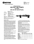
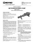
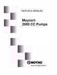
Section:
METERING/DOSING PUMPS
Page: 1 of 4
Date: May 1, 1998
SERVICE MANUAL
METERING/DOSING PUMP
CLOSE-COUPLED
B4015B, B4100B, B4190B, B4190C, B4015D, B4100D, AND B4190D MODELS
DESIGN FEATURES
Housing: Cast iron/316 SS
Pump Rotor: Chrome plated AISI 416 stainless steel/
Chrome plated 316 stainless steel
Pump Stator: Nitrile, Natural Rubber, EPDM,
Fluoroelastomer
Seal: Single and double mechanical (carbon/ceramic),
packing
Drive: 56C-face, 140TC-face motors and reducers,
gear reducers with 120 MM flange, 1" shaft
(Example SEW EURODRIVE R40F)
INSTALLATION
Mounting Position. Pump may be mounted in any position.
When mounting vertically, it is necessary to keep motor
above the seals to prevent possible seal leakage into motor.
Pre-Wetting. Prior to connecting pump, wet pump elements
and mechanical seal by adding fluid to be pumped into
suction and discharge ports.
Piping. Piping to pump should be self-supporting to avoid
excessive strain on pump housings. The suction port is
1-1/2" NPT and the discharge port is 1-1/4" NPT. Use pipe
“dope” or tape to facilitate disassembly and to provide seal
on pipe connections.
Electrical. Follow the wiring diagram on the motor
nameplate or inside the terminal box for the proper
connections. The wiring should be direct and conform to
local electrical codes. Check power connections for proper
voltage. Voltage variations must not exceed ±10% of
nameplate voltage. Motor is provided with internal automatic
overload protection.
To prevent damage to pump, pump rotation must be
clockwise when facing pump from motor end.
OPERATION
Self-Priming. With wetted pumping elements, the packed
pump is capable of 25 feet of suction lift with pipe size equal to
port size. Be sure suction lines are air tight or pump will
not self-prime. Self-priming capabilities will vary due to
fluid viscosity. Mechanical seal pump can suction lift to 15 feet.
DO NOT RUN DRY. Unit depends on liquid pumped for
lubrication. For proper lubrication, flow rate should be at
least 10% of rated capacity.
Storage. Always drain pump for extended storage periods
by removing bottom drain plug in pump body.
Pressure Limits. See Table 1 for maximum discharge of
each model.
Table 1
Models 4015
Max. pressure 300 PSI, 20 bar
Models 4100
Max. pressure 300 PSI, 20 bar
Models 4190
Max. pressure 175 PSI, 12 bar
Temperature Limits. Unit is capable for service at 10°F
to 210°F with nitrile, and to 260°F with EPDM, 185°F
with natural rubber, and 350°F with fluoroelastomer.
Note, an undersize rotor may be required for elevated
temperature applications.
TROUBLESHOOTING
WARNING: Before making adjustments, disconnect
power source and thoroughly bleed pressure
from system prior to disassembly. Failure to
do so could lead to electric shock or
serious bodily harm.
Failure to Pump.
1. Motor will not start: Check power supply. Voltage must be
±10% of nameplate rating when motor is in locked rotor
condition. Check for faulty capacitor on 1 phase models.
2. Motor runs and thermally kicks out: Check for excessive
discharge pressure. Check for defective centrifugal switch
on 1 phase models. Increase ventilation to motor. Do not
use less than #14 wire size.
Page 2
3. Stator torn; possible excessive pressure: Replace stator,
check pressure at discharge port.
4. Flexible joint broken; possible excessive pressure:
Replace joint, check pressure at discharge port.
5. Wrong rotation (3 phase only): Rotation must be
clockwise when facing pump from motor end. Reverse the
connections of any two line leads to the motor.
Pump Overloads.
9. Clean and inspect the flexible joint (24) looking for
excessive play and breaks in the rubber boots. If sealing
boots are damaged replace the flexible joint.
10. If packed model skip to Step 14.
Single Seal. Remove the mechanical seal (69) spring
and spring retainer from the drive shaft assembly (26).
Double Seal. Remove seal housing (71) and O-ring
(72), inspect, replace if necessary.
1. Excessive discharge pressure. Check pressure at
discharge port for maximum ratings given in Table 1.
11. Remove the rotational portion of the mechanical seal
from the drive shaft (26).
2. Fluid viscosity too high: Limit fluid viscosity per “How to
Select” calculations.
12. Remove the seal housing (3) or seal gland (73) from the
drive adapter casting (1).
Noisy Operation.
13. Remove the mechanical seal stationary from the seal
housing (3) (71) and seal gland (73). Replace seal
components if worn. Go to Step 16.
1. Excessive suction lift or vacuum: Maximum suction lift is
25 feet for water.
2. Suction line too small: Check pipe size. Be sure lines are
free from obstructions.
3. Pump Cavitates: At pump speed of 1725 rpm. Viscosity of
fluid should not exceed 100 CP or 500 SSU.
4. Flexible joint worn: Replace joint. Check pressure at
discharge port.
5. Insufficient mounting: Mount to a firm base. Vibration
induced noise can be reduced by using mount pads and
short sections of hose on suction and discharge ports.
Seal Leakage.
1. Leakage at startup: If leakage is slight, allow pump to run
several hours to let faces run in.
2. Persistent seal leakage: Faces may be cracked from
freezing or thermal shock. Replace seal.
Pump Will Not Prime.
1. Air leak on suction side: Check pipe connections.
PUMP DISASSEMBLY
WARNING: Before disassembling pump, disconnect
power source and thoroughly bleed
pressure from system. Failure to do so
could result in electric shock or serious
bodily harm.
1. Remove suction and discharge piping. Drain pump body
by removing drain plug (261).
2. Remove discharge coupling (9) from stator (21).
3. Remove stator support clamp (40).
4. Remove stator (21) by unthreading from the suction
housing (2). Lock rotor from turning by inserting a punch
into the hole located in the center of the flexible joint (24).
This will aid in removing the stator.
5. Remove the stator support retainer (39) if desired.
14. Remove the stuffing box (4) from the drive adapter
casting (1).
15. Remove the packing gland halves (65) from the studs
and remove the worn packing (72).
16. Remove the set screws (27) from the drive shaft
assembly (26).
17. Remove the drive shaft assembly (26) from the
motor/gearmotor shaft.
18. Remove the drive adapter casting from the motor/
gearmotor. This completes the pump disassembly.
PUMP ASSEMBLY
1. Mount the drive adapter casting (1) to the
motor/gearmotor, using appropriate hardware with the
windows horizontal.
2. Slide the drive shaft assembly (26) onto the motor/
gearmotor shaft, seating firmly against the shaft end.
3. Install the set screws (27) into the drive shaft assembly
(26) locking the drive shaft assembly to the
motor/gearmotor shaft.
4. On packed pump skip to Step 5.
Install the mechanical seal (69) (70) using the following
procedure:
a. Clean and oil sealing faces using clean oil (not grease).
CAUTION: Do not use oil on EPDM parts. Substitute
glycerin or soap and water.
b. Oil outer surfaces of the seal seat, and push seat
assembly into the seal housing (3) and seal gland on
double seals.
c. Slide the seal housing (3) or seal gland (73) onto
the drive shaft assembly (26) seating into the drive
adapter (1).
6. Remove the suction housing (2) by removing the screws
(112) and lock washers (215).
d. After cleaning and oiling the shaft, slide the seal body
along the drive shaft assembly (26) until it meets the
seal seat.
7. Remove O-Ring (270) from the seal housing (3) (71) or
the stuffing box (4). Inspect and replace if necessary.
e. Install the seal spring and spring retainer or second
seal body on the shaft.
8. Remove the rotor & shaft pins (46) from the flexible joint
(24). Support the joint/rotor while removing with a small
punch. These pins should not be reused. Replace with
new pins upon reassembly.
f. On double seal models, insert seal stationary into seal
housing (71), mount O-ring (72) and slide onto shaft,
enclosing the double seal.
Page 3
11. Slide stator (21) onto rotor (22) using hand soap or
equivalent as lubrication. Thread stator into suction
housing (2) using pipe “dope” or sealing tape to ensure
a leak-proof seal. To keep the rotor from turning, insert a
punch into the hole in the flexible joint.
5. On packed pumps perform the following:
a. Insert the packing rings (72) into the stuffing box
alternating the joints 90˚.
b. Install the packing gland halves (65) on the studs (70)
without tightening on the packing.
12. Slide stator support retainer ring (39) onto the stator.
c. Slide the stuffing box assembly onto the drive shaft
assembly (26). Set the studs horizontal, seating the
stuffing box into the drive adapter casting.
13. Use the stator support clamp (40) to connect the stator
support (38).
14. Thread discharge coupling (9) onto the stator (21) using
pipe “dope” or sealing tape to ensure a leak-proof seal.
6. Insert the flexible joint (24) into the drive shaft assembly
(26). Insert shaft pin (46) into the hole using a small
punch. The seal spring will move to allow clearance for
insertion. The spring retainer should rest against the
flexible joint (24) after pin insertion.
15. Lubricate rotor and stator by filling the suction housing
with fluid to be pumped.
16. Firmly mount the pump. Connect suction and discharge
piping and power source.
7. Support flexible joint and insert rotor (22) aligning holes
for insertion of rotor pin (46) using a small punch.
8. Insert O-Ring (270) into the groove in the seal housing
(3) or stuffing box (4).
PARTS LIST
To determine part numbers for all parts, enter the table on
the following page with the item number from the pump
illustration below. Then locate the part number under the
applicable model number. Notice the type column identifies
the materials of construction. Parts listed with one part
number for example are applicable to all models.
9. Install the drain plug (261) into suction housing (2) using
pipe “dope” or sealing tape to ensure a leak-proof seal.
10. Attach the suction housing (2) to the drive adapter
casting, using screws (112) and lockwashers (215).
Note, a gap will remain between the suction housing
and drive adapter casting.
73
71
70
Double Seal
Models
CAUTION: When mounting
motor, gearmotor or reducer,
use care in coupling the
pump shaft to the motor shaft
to avoid seal damage.
3
Single Seal
Models
3
270
72
69
1
27
26
270
Packing
Models
4
261
70
65
215
112
72
21
300
24
2
40
39
22
46
38
Remove two positioning set
screws after mounting drive
9
Page 4
CLOSE COUPLED MODELS PARTS LIST
PUMP MODELS
Item
Type
1
CD/SS
2
CD
2
SS
3
CD/SS
4
CD/SS
9
CD
9
SS
21
Q
21
R
21
B
21
F
22
CD
22
SS
24
Q, R
24
B
24
F
26 CD/SS
27 CD/SS
38 CD/SS
39 CD/SS
40 CD/SS
46 CD/SS
65 CD/SS
69
Q, R
69
B
69
F
69
Q, R
69
B
69
F
70 CD/SS
70
Q, R
70
B
70
F
71 CD/SS
72 CD/SS
72 Q, R, B, F
73 CD/SS
112 CD/SS
215 CD/SS
261
CD
261
SS
270
Q, R
270
B
270
F
300 CD/SS
Description
Drive Adapter
Suction Housing
Suction Housing
Seal Housing
Stuffing Box
Discharge Coupling
Discharge Coupling
Stator
Stator
Stator
Stator
Rotor
Rotor
Flexible Joint
Flexible Joint
Flexible Joint
Drive Shaft Assy.
Set Screw
Stator Support
Sta. Sup. Retainer
Clamp Assy.
Rotor/Shaft Pin
Packing Gland Half
Mechanical Seal Std.
Mechanical Seal Std.
Mechanical Seal Std.
Mechanical Seal Std.
Mechanical Seal Std.
Mechanical Seal Std.
Stud
Double Mech. Seal
Double Mech. Seal
Double Mech. Seal
Seal Housing, Double
Packing Set
O-Ring
Seal Gland, Double
Screw
Lock Washer
Drain Plug
Drain Plug
O-Ring
O-Ring
O-Ring
Name Plate
Req.
1
1
1
1
1
1
1
1
1
1
1
1
1
1
1
1
1
2
1
1
1
2
2
1
1
1
1
1
1
2
1
1
1
1
1
1
1
4
4
1
1
1
1
1
1
B4015B
B4100B
B4190B
B4190C
B4015D
350168801
3403923104
3403923204
3403923304
3403923504
3403927007
3403927015
3403924104
3403924204
3403924309
3403924504
3403928007
3403928015
3403943001
3403932001
3403932007
3403930007
3403934007
3205341020
3205342020
3403925104 3403925104 3403923104
3403925204 3403925204 3403923204
3403925304 3403925304 3403923304
3403925504 3403925504 3403923504
3403929007 3403929007 3403927007
3403929015 3403929015 3403927015
3308811001
3308811003
3308811005
3403943002
6060340040
3403945001
3201733000
3204277000 and 3201734000
3204069001
3403933007
3202424000
3206379000
3206501000
3206460000
3206502000
3206503000
3208591000
3208652000
3208652001
3208652002
3403986015
3403396002
3207902128
3403985015
6191520141
6230010401
6100120031
6100420030
3207902134
3207904134
3207905134
3208597000
B4100D
B4190D
3501688003
3403924104
3403924204
3403924304
3403924504
3403928007
3403928015
3403925104
3403925204
3403925304
3240392504
3403929007
3403929015
3403943003
Note: For further information, call 800-845-1310 (Western USA)
800-325-1331 (Central & Eastern USA), or 937-327-3553 (Ohio)
© 1998 by Moyno, Inc.
® Moyno is a registered trademark of Moyno, Inc.
Moyno, Inc. is a Unit of Robbins & Myers, Inc.
320-8595-000
Printed in U.S.A.
Double The Length Of Your
Moyno Pump Warranty For FREE!
For your free pump warranty extension, choose from one of the three options below:
1. Go to www.moyno.com and fill out the registration form online
2. Mail this form by placing it in an envelope and sending it to: Moyno, Inc.
Attn: Tish Wilson
P. O. Box 960
3. Fax this form to 937-327-3177
Springfield, OH 45501-0960
U.S.A.
Thank you for choosing a Moyno Pump. Please take the time to complete this warranty registration form.Upon receipt
of your form, your standard limited warranty on defective material and workmanship will be extended to twice the standard
period of time at no additional cost to you. We appreciate your business and look forward to serving you in the future.
MOYNO
™
Always Insist on Genuine Moyno Replacement Parts!
Moyno® Pump Warranty Registration
Pump Model #
Pump Serial #
Purchased From
Date Purchased
Your Name
Your Title
Your Company Name
Address
City/State (Province)/Zip Code
Phone Number
Fax Number
E-mail
Application for Which This Pump Was Purchased
Material
Flow Rate
Process Temperature
Operating Speed
Viscosity
pH Value
Hours Operated per Day
Continuous
Intermittent
Discharge Pressure
Suction Pressure
NPSH Available
Percent of Solids
Particle Size
Abrasion Rating
How Did You First Hear of Moyno Pumps?
❑ Advertisement
❑ Distributor Salesperson
Thank You!
❑ Postcard
❑ Trade Show
❑ Previous Experience With Moyno Pumps
❑ Referral
❑ Other – Explain Below