1
MODEL HPG200
ADVANCED SUBMERSIBLE
GRINDER PUMP
INSTALLATION AND SERVICE MANUAL
NOTE! To the installer: Please make sure you provide this manual to the owner of the equipment or to the responsible
party who maintains the system.
Item # E-03-407 | Part # 5625-407-1 | © 2013 Pentair Ltd. | 11/20/13
General
Information
Attention:
This manual contains important
information for the safe use of
this product. Read this manual
completely before using this
product and refer to it often
for con
tin
ued safe product use.
DO NOT THROW AWAY OR
LOSE THIS MAN
U
AL. Keep
it in a safe place so that you
may refer to it often. Reasonable
care and safe methods should be
practiced. Check local codes and
requirements before installation.
WARNING: Before handling
these pumps and controls,
always disconnect the power
first. Do not smoke or use
sparkable electrical devices or
flames in a septic (gaseous) or
possible septic sump.
Pump Cautions
and Warnings
CALIFORNIA PROPOSITION
65 WARNING:
This product and
related accessories contain chemicals
known to the State of California to
cause cancer, birth defects or other
reproductive harm.
1.CAUTION – To reduce risk
of electrical shock, pull plug
before servicing this pump.
2.WARNING – Risk of electrical
shock – this pump has not
been investigated for use in
swimming pool areas.
3.WARNING – See installation
and service manual for proper
installation.
4.WARNING – To reduce risk
of electrical shock, pump is
provided with grounding wire.
Be certain that it is connected
to ground.
2
5.WARNING – Hazardous
moving parts. To reduce the
risk of injury, disconnect power
before servicing pump.
6.CAUTION – To reduce the risk
of electrical shock, DO NOT
remove cord or strain relief.
DO NOT connect conduit to
pump. Electrical installations
shall be in accordance with the
National Electrical Code and
all applicable local codes and
ordinances.
7.
For use with maximum
140°F water.
8.Septic tank should be vented in
accordance with local plumbing
codes and should not be
installed in locations classified as
hazardous, in accordance with
the National Electrical Code,
ANSI/NFPA 70-1999.
9.WARNING – Severe injury
may result from accidental
contact with moving cutters.
Keep clothing, hands and
feet away from cutters any
time power is connected to
the pump.
10.CAUTION – Never work on
pump with power on. Make
sure that the ground wire is
securely connected and that
the unit is properly grounded
in accordance with local codes.
ThePump
Pump Description:
The
Hydromatic ®
pumps
covered by these instructions are
submersible grinder pumps.
The cutter blades are on the
suction side of the cen
trif
u
gal
pump impeller and dis
charge
directly into the inlet of the
impeller. The integral stainless
steel pump motor shaft is sealed
by two me
chan
i
cal seals with
an oil chamber between the
seals to pro
vide lubrication for
both seal faces.
Two ball bearings are used to
handle the loads in this design,
similar to most of Hydromatic’s
solids handling pumps. The upper
bearing takes radial load, while
the larger lower bearing handles
both thrust and radial loads.
Both bearings are permanently
lubricated by the dielectric oil in
the motor housing. The motor is
fixed within the motor housing
and is com
plete
ly submerged in
the di
elec
tric oil for maximum
heat transfer. The motor housing
and seal chamber are completely
sealed with O-rings located at
mating part faces.
The power cord entry system is
designed to give double sealing.
The chamfered pilot of the motor
housing mates with the molded
cord end to form the first seal.
The cord grip forms the second
seal around the molded cord
end and provides strain relief.
The ca
ble on the HPG model
includes the leads for both heat
sensors (motor protection) and
the seal sen
sor lead for seal
leakage detection.
The cutters are designed to be self
adjusting and will not need to be
shimmed or reset.
Application:
These pumps are designed for
either residential or industrial
sewage discharge applications with
a pH ranging from 5 to 9, specific
gravities from 0.9 to 1.1, viscosities
ranging from 28 to 35 S.S.U., and
temperatures up to 140°F.
Codes:
All local wiring codes must
be observed. Consult the local
inspector before installation
to avoid costly delays that can
occur due to rejection after job
is finished.
Pump Installation
Unpacking Pump:
Remove pump from carton.
When unpacking unit, check for
con
c ealed damage. Claims
for damage must be made at
the receiving end through the
delivery carrier. Dam
age cannot
be processed from the factory.
Location:
If pumps are installed in an
existing basin or concrete sump,
the piping can either be connected
permanently or rails and brackets
can be furnished for mounting to
walls of basin. In either case, be
sure that the Hydromatic® solids
handling check valve is used and
that the pumps are submerged
in a vertical position. The
complete factory built packaged
system is recommended for the
most satisfactory installation
and generally for the lowest cost
where expensive installation labor
is involved.
Electrical Connections:
Make all connections from motor
to control panel to comply with
local codes.
CAUTION: Make sure that
the ground wire is securely
connected and that the unit
is properly grounded in
accordance with local codes.
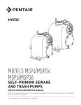
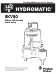
ELECTRICAL CONNECTIONS
1 Phase
3 Phase
GreenGround
Ground
Red
Start Power Line
Power Line
White Main Power Line
Power Line
Black Common Power Line
Power Line
Orange
Seal Failure
Seal Failure
Blue Heat Sensor
Heat Sensor
White Heat Sensor
Heat Sensor
w/ black
stripe
6(1625/($'6
:+,7(:%/$&.675,3(3
%/8(3
25$1*(6($/352%(
2.Run water into sump until
motor is covered.
02725/($'6
96,1*/(3+$6(
:+,7(
/
7
:+,7(
%/$&.
/
5('
/
7
7
%/$&.
33853/(
3%52:1
5('
9'8$/92/7$*(7+5((3+$6(
:+,7( %/$&.
5('
/
/
/ 33853/(
3'$5.%52:1
7
7
7
%/8(
7$1
7
7
3,1.
7
<(//2:
25$1*(
7
5('
7
/7%52:1
7
%/$&.
/$9(1'(5
9$1'97+5((3+$6(
:+,7(
/
7
%/8(
%/$&.
/
5('
/
7
33853/(
3%52:1
7
7$1
25$1*(
9'8$/92/7$*(7+5((3+$6(
:+,7(
/
7
%/8(
7
3,1.
7
<(//2:
%/$&.
/
7
5('
/
3/3853/(
7
3'$5.%52:1
7
7
7$1
5('
7
25$1*(
(LT. BROWN)
%/$&.
is single phase, no rotation
check is necessary.
7
/$9(1'(5
Pump Operations
Starting the Pump:
To start the pump, perform the
following steps in order:
1.If pump is 3 phase, the
rotation of the cutters must
first be checked. Lift pump
from sump, lay it down, and
quickly turn pump on and
then off. The cutter should
turn counterclockwise when
viewed from the suction. If
rotation is wrong, turn off
main breaker and interchange
any two line leads to motor
to correct rotation. If pump
3.Open the gate valve in the
discharge line.
4. Turn pump on. If pump runs
and sump liquid does not
pump down, stop pump and
close discharge gate valve.
Then lift pump until sealing
flange is open to vent off
trapped air. Lower pump,
open discharge valve, and
start the pump again.
5. If pump is 3 phase, piped-in
permanently, and still does not
operate properly after venting,
rotation is wrong and can be
reversed by interchanging any
two line leads.
6. Level controls should be set
so that pump turns off when
level is about 2 inches above
inlet of pump suction and
turns on when level is about 2
inches above motor.
7. If problems occur check the
power source. Make sure
a separate supply line is
available. Verify the voltage
supply.
8.Check resistance windings
(see chart). If not within
guidelines, return pump to
an authorized Hydromatic
service center.
3
Pump Maintenance
Pump Disassembly, Inspection,
Reassembly:
1.Close gate valve at pump
discharge.
2. Turn off circuit breaker.
3. Remove pump from sump.
4.Unscrew cap screws and
remove the volute from the
pump. Note: under certain
circumstances it may be
necessary to remove the
discharge piping.
5. Remove the axial and radial
cutters from the shaft and
inspect for excessive wear
or damage. If the axial cutter
is damaged or is excessively
worn, flip the axial cutter to
the unworn side and reattach
to the radial cutter.
6.Inspect the stationary cutter
for wear or damage. If the
cutter requires removal,
loosen the machine screw in
cutter retainer and remove
cutter retainer and slide
the cutter out of the volute.
If cutter is damaged or worn,
reinstall on the opposite side,
making sure to snug (DO
NOT OVERTIGHTEN) the
Allen head screw. It is good
practice to add a light coat of
removable locking adhesive
to the Allen screw.
7.Inspect the volute O-ring
for damage. If cracked or
torn, replace with the proper
Hydromatic® part.
8.To reassemble the pump,
place the cutters on the
splined shaft and orient
the cutters so that the axial
cutter blades fall between the
impeller vanes. Hold tension
4
on the cutters and replace
the volute and cap screws,
making sure the O-ring is
placed in the proper position.
Evenly torque the cap screws.
Replacing Seals on Dual Seal
HPG200 Model:
1.Drain the oil in the seal
chamber by removing the
drain plug on the side of the
pump. If it contains water,
the lower seal has failed
and should be replaced. The
motor hous
ing should be
drained and the upper seal
replaced if the lower seal has
failed, since foreign material
in the seal chamber may have
damaged the upper seal.
2.
Remove the volute and
cutters per the instrutions listed
under the Pump Disassembly,
Inspection, Reassembly section
in this manual.
3.To remove the impeller,
secure the shaft by threading
the radial cutter onto the shaft
and holding it with a pair of
pliers. Hold a wood block
against the impeller vane and
tap it with a hammer until it
spins off.
4.Using a pair of snap ring
pliers, remove the snap
ring that secures the lower
seal. Remove the lower seal
rotating elements by sliding
the spring off the shaft. Then
using two screwdrivers, slide
the carbon assembly off by
prying on the retaining ring.
5. Loosen and remove the cap
screws that hold on the seal
housing, then re
move the
seal housing. Using a socket
that will fit onto the back of
the seal, tap the sta
tionary
seal assembly out of the
seal housing.
6.Using a pair of snap ring
pliers, remove the snap ring
that secures the up
per seal.
Remove the spring retainer
and spring from the shaft, and
using the same method as used
for the lower seal, remove the
carbon seal assembly.
7. With a pair of screwdrivers,
pry up on the seal/bearing
plate. Remove the seal/
bearing plate until you have
access to the seal sensor
wire, then carefully pull the
seal sensor wire off the seal
probe which will allow the
complete removal of the seal
bearing plate.
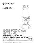
WINDING RESISTANCE IN OHMS
hp
RPM
VOLT
PHASE BLACK TO BLACK
RED WHITE
TO RED TO WHITE
2
3450
208
2
3450
230
2
3450
200
2
3450
230
23450460
2
3450
575
1 1.305.086.35
1 1.578.009.57
3 2.862.862.86
3 3.313.313.31
3 13.2513.2513.25
3 28.228.228.2
MAXIMUM AMP & WINDING RESISTANCE VALUES
SINGLE PHASE
BLACK - COMMON
WHITE - MAIN
RED - START
THREE PHASE
BLACK - L1
WHITE - L2
RED - L3
8. Take a socket and tap out the
stationary portion of the seal
from the seal/bearing plate in
the same manner as used for
the lower stationary seal.
9.After checking both of the
O-rings, replace the seal
bearing plate in the motor
housing, making sure that
the seal sensor wire has been
reattached to the seal probe.
Use O-ring lube to prevent
cutting in assembly.
10. Take the stationary portion
of the new seal, and lube the
rubber material with a good
quality dielectric oil. Press
the stationary portion of
the new seal into the seal/
bearing plate.
CAUTION: Do not reuse old
seal parts. Replace all parts
with new. Mixing old and new
parts could cause immediate
seal failure.
11.
Using a good quality
dielectric oil, lube the rubber
material on the carbon seal
assembly and press it on
the shaft. Place the spring
and the seal retainer on the
shaft as removed. Replace the
snap ring.
12. Carefully place the seal housing onto the seal bearing
plate, replace the cap screws,
and evenly tighten.
13. Using a pressure gauge with a
fill stem, pressurize the motor
housing to no more than 7 psig
with dried air and check for
leaks. If after several minutes
the gauge reads the same,
the seal is good and you can
continue with assembly.
NOTE: It is normal to observe
some air bubbles in the seal
area initially as the seal seats.
If bubbles do not stop within
a few seconds, the seal is
either not properly installed or
is damaged.
14. Following the same procedure
outlined in steps 10 through 13,
install the lower seal assembly.
Replace the impeller using a
removable locking adhesive.
15.Reassemble the cut
ters and
volute as outlined in the
Pump Disassembly, Inspection,
Reassembly section of this
manual.
16.Refill all cham
bers with a
good quality dielectric oil.
Fill the motor housing so that
the tops of the motor windings
have been covered (2500 ml),
but leave an air gap to allow
for ex
pan
sion of the oil.
Fill the seal chamber with
700 ml of oil so that an air
gap also exists.
Replacing Motor Stator:
1. If the replacement of the stator
is necessary, first follow the
disassembly steps outlined
in the previous sections of
the manual.
2.
Remove the shaft rotor
assembly from the motor
housing, making note that a
wave washer is used on the
top of the upper bearing.
3.Place motor housing vertically
on the bench and remove the
cord grip. Carefully remove
the power cord from the
pump, making sure that the
wires are not damaged. Clip
the power cable leads, taking
note of the wire connections,
and then remove the power
cable.
4.Turn the motor housing
over and remove the stator
bolts from the stator, then
remove the stator from the
motor housing.
5.Place new stator into the
motor housing while pulling
the new leads through the
power cord opening in the
motor housing. Replace
the stator bolts and tighten.
Replace the seal sensor wire
along the side of the stator.
6. Attach the power cord to the
stator leads and the sensor leads
using insulated butt connector.
Once attached, carefully tuck
the wires into the motor
housing making sure that they
will not come in contact with
the rotor. Press the power cord
molded end into chamber in
the motor housing.
7. Apply a sealant to the threads
on the body of the cord grip that
will enter the motor housing,
then slide onto the power cord
and tighten snugly.
DO NOT OVERTIGHTEN.
Attach the cord grip nut onto
the cord grip and snug.
8.Examine the bearings on
the shaft/rotor assembly. If
when rotated they feel rough,
replace. When reinstalling
new bearings, press only on
the inner ring of the bearing
or damage may occur.
9. Replace the wave washer into
the upper bearing pocket in the
motor housing, then reinstall
the rotor and shaft assembly.
5
10. Follow the previously outlined
steps to reassemble the pump
from this point.
11.Always run pump for a
few seconds after assembly
work to be sure all parts run
smoothly before replacing it
in the sump. Check again for
correct rotation. Pump should
rotate counterclockwise when
viewed from the suction end.
NOTE: When applying power,
be sure the pump is restrained
from turning by holding the
pump at the motor hous
ing,
or by clamping it in a holding
fixture.
Pump
Troubleshooting
Insufficient discharge pressure
1. Wrong rotation
2. Air or gases in liquid
3. Impeller damages
4. Incorrect impeller diameter
5. Speed too low
Pump overloads motor
1. Wrong rotation
2. Specific gravity or viscosity
of liquid too high
3. Speed too high
4.Head lower than rat
ing,
pumping too much liquid
5. Pump clogged
6. Defective bearings
7. Defective impeller
Below is a list of troubles and
their probable causes:
Pump is noisy
No liquid delivered
2.No axial clearance be
tween
impeller and volute
1. Pump air bound
2. Discharge head too high
3. Pump or piping plugged
4. Wrong rotation
5. Speed too low
Insufficient liquid delivered
1. Discharge head too high
2. Impeller or cutters impartially
plugged or damaged
3. Wrong rotation
4. Incorrect diameter impeller
5. Speed too low
6
1. Defective bearings
3.
No
diametral
clear
ance
between radial cutter and
cutter ring
If the cause of the trouble cannot
be determined and cor
rect
ed as
outlined above, contact your
nearest factory representative.
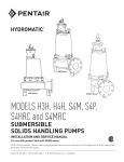
HPG200 Parts List
ORDERING REPLACEMENT PARTS: Product improvements are made from time to time. The latest part design will be fur
nished as long as it is interchangeable with the old part.When ordering replacement parts, always furnish the following information:
(1) pump serial number, (2) pump model and size, (3) part description, (4) part number, (5) impeller diameter (if ordering impeller),
(6) quantity required and (7) shipping instructions.
Ref.
No.
Part
No.
1
144240025
144240115
116750001
2
3
4
5
6
7
8
9
10
11
12
13
14
15
16
17
18
19
20
21
22
23
24
25
26
27
28
29
30
31
32
33
*
Part
Description
Qty.
POWER CORD – 20'
POWER CORD – 35'
BUTT CONNECTOR
230, 1f; 200, 1f; 575, 3f; 200, 3f
230, 3f
460, 3f
116910001
060000141
134880002
084720015
05876A120
003000001
000730011
001500421
070330023
070330043
070330063
055060022
054050012
148850001
055700051
055050002
000300041
077630001
135001002
19100A012
009750021
134890012
001010111
000650271
000250091
05454A009
21573C100
21573C102
21573C103
21573C101
21573C104
108321005
108231005
134950002
134941002
08565A013
000640011
134962002
517004027
131880001
BUTT CONNECTOR
WIRE w/TERMINAL
SEAL/BEARING PLATE
SEAL FAILURE ASSY.
O-RING
SHAFT SEAL – 1"
WIRE CONNECTOR – 230, 3f
O-RING
IMPELLER – 5.00"
IMPELLER – 4.50"
IMPELLER – 4.00"
AXIAL CUTTER
RADIAL CUTTER
MACHINE SCREW
IMPELLER WASHER
STATIONARY CUTTER
MACHINE SCREW
CUTTER RETAINER
VOLUTE CASE
HEX HEAD CAP SCREW – 5/16
RETAINING RING
SEAL HOUSING
HEX HEAD CAP SCREW – 5/16
BALL BEARING
MACHINE SCREW PER B/M
LOCK WASHER
STATOR – 230V, 1f
STATOR – 230–460V, 3f
STATOR – 575V, 3f
STATOR – 200V, 3f
STATOR – 200V, 1f
ROTOR/SHAFT – 1f
ROTOR/SHAFT – 3f
HORIZONTAL ADAPTER
MOTOR HOUSING
BALL BEARING
WAVE SPRING
VERTICAL ADAPTER (std.)
SEAL KIT
CUTTER SHIM
006280391
IMPELLER SHIM
1
1
S
S
S
6
3
9
3
1
1
1
2
2
1
1
1
1
1
1
1
1
1
1
3
1
1
4
2
1
4
1
4
4
1
1
1
1
1
1
1
1
1
1
1
1
As
Req’d.
As
Req’d.
32
31
1
30
28
2
3
9
27
25
26
4
24
5
6
23
7
22
29
8
8
10
21
33
11
20
12
13
14
15
16
17
18
19
Notes: S– Parts in Seal Kit
– Fill oil to above motor windings
7
STANDARD LIMITED WARRANTY
Pentair Hydromatic® warrants its products against defects in material and workmanship for a period of 12 months
from the date of shipment from Pentair Hydromatic or 18 months from the manufacturing date, whichever
occurs first – provided that such products are used in compliance with the requirements of the Pentair Hydromatic
catalog and technical manuals for use in pumping raw sewage, municipal wastewater or similar, abrasive-free,
noncorrosive liquids.
During the warranty period and subject to the conditions set forth, Pentair Hydromatic, at its discretion, will repair
or replace to the original user, the parts that prove defective in materials and workmanship. Pentair Hydromatic
reserves the right to change or improve its products or any portions thereof without being obligated to provide such
a change or improvement for prior sold and/or shipped units.
Start-up reports and electrical schematics may be required to support warranty claims. Submit at the time of start up
through the Pentair Hydromatic website: http://forms.pentairliterature.com/startupform/startupform.asp?type=h.
Warranty is effective only if Pentair Hydromatic authorized control panels are used. All seal fail and heat sensing
devices must be hooked up, functional and monitored or this warranty will be void. Pentair Hydromatic will cover
only the lower seal and labor thereof for all dual seal pumps. Under no circumstance will Pentair Hydromatic be
responsible for the cost of field labor, travel expenses, rented equipment, removal/reinstallation costs or freight
expenses to and from the factory or an authorized Pentair Hydromatic service facility.
This limited warranty will not apply: (a) to defects or malfunctions resulting from failure to properly install, operate or
maintain the unit in accordance with the printed instructions provided; (b) to failures resulting from abuse, accident
or negligence; (c) to normal maintenance services and parts used in connection with such service; (d) to units that
are not installed in accordance with applicable local codes, ordinances and good trade practices; (e) if the unit is
moved from its original installation location; (f) if unit is used for purposes other than for what it is designed and
manufactured; (g) to any unit that has been repaired or altered by anyone other than Pentair Hydromatic or an
authorized Pentair Hydromatic service provider; (h) to any unit that has been repaired using non factory specified/
OEM parts.
Warranty Exclusions: Pentair HYDROMATIC MAKES NO EXPRESS OR IMPLIED WARRANTIES THAT EXTEND
BEYOND THE DESCRIPTION ON THE FACE HEREOF. Pentair HYDROMATIC SPECIFICALLY DISCLAIMS THE
IMPLIED WARRANTIES OF MERCHANTABILITY AND FITNESS FOR ANY PARTICULAR PURPOSE.
Liability Limitation: IN NO EVENT SHALL Pentair HYDROMATIC BE LIABLE OR RESPONSIBLE FOR
CONSEQUENTIAL, INCIDENTAL OR SPECIAL DAMAGES RESULTING FROM OR RELATED IN ANY MANNER TO
ANY Pentair HYDROMATIC PRODUCT OR PARTS THEREOF. PERSONAL INJURY AND/OR PROPERTY DAMAGE
MAY RESULT FROM IMPROPER INSTALLATION. Pentair HYDROMATIC DISCLAIMS ALL LIABILITY, INCLUDING
LIABILITY UNDER THIS WARRANTY, FOR IMPROPER INSTALLATION. Pentair HYDROMATIC RECOMMENDS
INSTALLATION BY PROFESSIONALS.
Some states do not permit some or all of the above warranty limitations or the exclusion or limitation of incidental or
consequential damages and therefore such limitations may not apply to you. No warranties or representations at any
time made by any representatives of Pentair Hydromatic shall vary or expand the provision hereof.
740 EAST 9TH STREET
490 Pinebush Road, Unit #4
ASHLAND, OHIO, USA 44805
CAMBRIDGE, ONTARIO, CANADA N1T 0A5
419-289-1144800-363-PUMP
WWW.HYDROMATIC.COM
Warranty Rev. 12/13