1
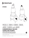
MODEL S
SUBMERSIBLE
SOLIDS HANDLING PUMP
INSTALLATION AND SERVICE MANUAL
For use with product built with Marathon® motor.
NOTE! To the installer: Please make sure you provide this manual to the owner of the equipment or to the responsible
party who maintains the system.
Item # E-03-304 | Part # 5625-304-1 | © 2012 Pentair Pump Group, Inc. | 10/19/12
CALIFORNIA PROPOSITION
General65 WARNING:
This
Information
Thank you for purchasing your
Hydromatic® pump. To help ensure
years of trouble-free operation,
please read the following manual
carefully.
Before Operation:
Read the following in
struc
tions care
ful
ly. Reasonable care
and safe meth
ods should be
practiced. Check local codes and
requirements before installation.
Attention:
This manual contains important
information for the safe use of
this product. Read this manual
completely before using this
product and refer to it often
for con
tin
ued safe product use.
DO NOT THROW AWAY OR
LOSE THIS MAN
U
AL. Keep
it in a safe place so that you may
refer to it often.
Unpacking Pump:
Remove pump from carton.
When unpacking unit, check for
con
cealed damage. Claims for
damage must be made at the
receiving end through the delivery
carrier. Dam
age cannot be
processed from the factory.
WARNING: Before handling
these pumps and controls,
always disconnect the power
first. Do not smoke or use
sparkable electrical devices or
flames in a septic (gaseous) or
possible septic sump.
2
product and
related accessories contain
chemicals known to the State of
California to cause cancer, birth
defects or other reproductive
harm.
Pumps in Storage or Not
Operating:
Pumps with carbon ceramic seals
must have impellers manually
rotated (6 revolutions) after
setting nonoperational for 3
months or longer and prior to
electrical start-up.
Pumps with tungsten carbide seals
must have impellers manually
rotated (6 revolutions) after
setting non-operational for
3 weeks or longer and prior to
electrical start-up.
Seal Failure:
An electrode is installed in the
seal chamber so if any water
enters the chamber through the
first seal the electrode will be
energized and a signal will be
transmitted to the sensing unit at
ground surface, causing an alarm
function to energize.
In operation the seal failure unit
indicates only that there is some
water in the seal chamber. The
pump will continue to operate
without damage, but the seal
should be checked immediately
after failure is indicated.
NOTE: Failure to install such
a device negates all warranties
by Hydromatic.
Pump:
The S submersible pump is
supplied for 1 and 3 phase and
for 200, 230, 460 or 575 volts.
Power cable is supplied with the
green wire for ground. Be sure
green wire is connected to a good
ground such as water pipe or
ground stake.
Heat Sensors:
All motors have heat sensor units
embedded in the motor winding
to detect excessive heat. The heat
sensors are set to trip at 105°C, so
will not operate if dangerous heat
occurs. The sensors automatically
reset when motor cools to
safe temperature.
The sensors are connected in
series with the motor starter coil
so that the starter is tripped if heat
sensor opens. The motor starter is
equipped with overload heaters so
all normal overloads are protected
by the starter.
NOTE: Failure to install such a
device negates all warranties by
Hydromatic.
IMPORTANT: If Hydromatic
electrical starting equipment is
not supplied the heat sensor
circuit must be connected in
series with the starter coil or
warranty is void. Connection
diagram is included in this
manual.
Sump Level Control:
Sump level is controlled by
Hydromatic 3900 mercury switch
controls. The 3900 control is a
mercury tube switch sealed in a
solid polyurethane float. The float
is held in position in the sump by
weight attached to the power cord
above the float. The cord supports
the float and is adjusted for height
from the surface.
Typical duplex systems use three
controls: one set at turn-off, one
set at turn-on for one pump, and
one set for turn-on for two pumps.
Pumps alternate operation on each
successive cycle.
Two pumps operate together only
if sump level rises to the third
or override control. The override
control also brings on the second
pump in case of failure of the
first pump. Extra floats with
appropriate controls can be
supplied for alarm functions.
Triplex systems use four controls:
one set at turn-off, one set at
turn-on for one pump, one set
at turn-on for two pumps, and
one set at turn-on for three
pumps. Pumps alternate each
successive cycle.
Three pumps operate together
only if sump level rises to the
fourth control (second override).
This control also brings on the
third pump in case of failure of
either or both of the first two
pumps.
Alarm Controls:
The alarm level is usually set
above the override level so the
alarm will signal only if the
override level is exceeded.
However, some engineers prefer
to have the alarm level set below
the override level as it is possible
for one pump to fail and the other
pump to operate on the override
level with the sump level never
reaching the alarm level. This is
particularly true in cases of low
inflow capacity.
Electrical Control Panel:
It is recommended that the
Hydromatic control panel be used
with all pumps as proper starter
heaters and connections for heat
sensor wires are furnished.
IMPORTANT: If Hydromatic
electrical controls are not used
and the motor fails because of
improper components or if the
heat sensors are not properly
connected the warranty is void.
Hydromatic electrical equipment
is installed in a weatherproof
NEMA 3R enclosure. The
electrical equipment includes
a main circuit breaker for each
pump, a magnetic starter with
overload protection for each
pump, an H-O-A switch and run
light for each pump, an electric
alternator and a transformer to
provide appropriate control for
control circuit and alarms.
Overload Heaters:
If the Hydromatic electrical
panel is not used, starters with 3
leg overload protection must be
supplied. On 3 phase pumps
the heaters must be sized in
accordance with the name
plate
amps on the motor housing. The
amp draw on these submersible
mo
tors is slightly higher than
*Special junction box required for wire sizes larger than #4.
3
only with short dis
charge lines,
Generalotherwise water will return to the
sump and cause short cycling of
Information
the pump.
a corresponding horsepower
surface motor so heaters must be
sized by the nameplate rating.
Single phase pumps with
capacitor start have a run and
a start winding each drawing a
different current. To adequately
protect these windings with
the appropriate heaters consult
the factory.
IMPORTANT: If other than
Hydromatic starters are used
be sure the heat sensor wires
are connected in series with the
starter coil circuit.
Installation
Instructions
Installing Pump in Sump:
Before installing pump in sump
lay it on side and turn impeller
manually. Im
pel
ler may be
slightly stuck due to factory test
water so it must be broken loose
with small bar or screwdriver
in edge of vanes. The impeller
should turn freely.
Clean all trash and sticks from
sump and connect pump to piping.
A check valve must be installed
on each pump. A gate or plug
valve in each pump discharge
line is also rec
om
mend
ed. This
valve should be installed on the
discharge side of the check valve
so if nec
es
sary to service the
check valve the line pressure can
be cut off. Single pump systems
are sometimes installed without a
check valve where it is desirable
to self-drain the discharge line to
prevent freezing. This can be done
4
NEMA 4 Junction Box (Optional):
If electrical control panel is to be
set remote from the pump sump a
NEMA 4 junction box should be
used to make power and control
connections. The Hydromatic
NEMA 4 junction box is provid
ed with compression connectors
for sealing all wires. No sealing
com
pound is need
ed to make
connections waterproof.
Wiring diagrams are provided with
panel for making connections.
The size wire to use from panel to
sump depends on motor size and
distance in feet.
Be sure each wire is checked out
so that a wrong connection will
not be made. An ohm
me
ter or
Megger can be used to check wire
continuity.
Installing 3900 Mercury Switch
Controls:
The controls are supported by a
mounting bracket that is attached
to sump wall or cover or to the
NEMA 4 junction box.
Cord snubbers are used to hold the
cord in place. Control lever can be
changed at any time by loosening
the snub
ber and readjusting
cord length.
In either simplex or duplex
system the lower or turn-off
control is set just above the top
of volute so that the volute will
always be sub
merged dur
ing
the pumping cycle. The second
or turn-on con
trol is set about
24 inches above the lower
turn-off control.
More distance between turnon and turn-off controls can be
used but sew
age may be
come
septic and ex
ces
sive solids may
collect for the pump to handle. A
frequent pumping cycle is recom
mended for best operation.
If an alarm system is used
this control is usually set about 6
inches above the override control.
Some engineers as de
scribed
pre
vi
ous
ly prefer to have the
alarm control set below the
override control.
Making Electrical Connections:
All electrical wiring must be
in ac
cor
dance with local code,
and only competent electricians
should make the installations. A
set of prints is included for use
in making the in
stal
la
tion. All
wires should be checked for
grounds with an ohm
me
ter or
Megger after the connections are
made. This is important, as one
grounded wire can cause
considerable trouble.
IMPORTANT: If equipment
is not properly wired and
protected as recommended, the
warranty is void.
Heat Sensors and Seal Failure
Connections:
Be sure that heat sensor wires
are connected in series with the
starter coil. Connections are
pro
vid
ed on the terminal strip;
see wiring diagram.
If seal failure unit is used, con
nect as shown with seal failure
system. If seal failure unit is not
used, the two seal failure wires
are left open. Do not connect
power to these lines at any time.
to operate until level drops to
turn-off point.
5.Allow sump level to rise to
start other pump. Notice run
lights on panel; pumps should
alternate on each suc
ces
sive
cycle of operation.
6.Turn both H-O-A switches to
Auto position and allow sump
to fill to the override control
level.
7.Turn both switches to Auto
po
si
tion and both pumps
should start and operate
to
geth
er until level drops to
turn-off point.
8.Repeat this operation cycle
several times before leaving
the job.
9.Check voltage when pumps
are operating and check the
amp draw of each pump.
Check amps on each wire as
sometimes a high leg
will exist. One leg can be
some
what higher (5 to 10%)
Pump
Operation
Starting Systems:
1.Turn H-O-A switch to Off
position, then turn on main
circuit breakers.
2.Open all discharge valves
and al
low water to rise in
sump pump.
3.Turn H-O-A switch to Hand
po
si
tion on one pump and
notice op
er
a
tion. If pump is
noisy and vi
brates, rotation
is wrong. To change rotation
interchange any two line leads
to motor. Do not interchange
main incoming lines. If duplex
system, check second pump in
the same manner.
4. Now set both H-O-A switches
to Auto position and allow
water to rise in sump until
one pump starts. Allow pump
CONNECTION DIAGRAM FOR LEADS IN
MOTOR AND CONNECTION BOX
(Y) WYE MOTOR CONNECTIONS
230 VOLTS
5
4
6
5
4
9
8
7
9
8
7
3
L1
2
1
L3 GREEN
3
2
1
L2
L1
L2
Pump
Maintenance
As the motors are oil filled, no
lubrication or other maintenance
is required.
If a seal failure unit is used, no
at
ten
tion is necessary as long
as the seal shows satisfactory
operation.
If seal failure is not used, the
pump should be lifted once every
two years and the oil be drained
from the seal chamber to check
for water.
If the pump is used on a HydrO-Rail system, it should be
lifted once every six months and
checked for corrosion and wear.
HEAT SENSORS AND SEAL FAILURE CONNECTIONS
FOR ANY VOLTAGE MOTOR
ELECTRODE
460 VOLTS
6
without caus
ing trouble. For
excessive amp draw on one
leg, the power company should
be consulted.
HEAT SENSORS
IN MOTOR
WINDINGS
BLACK
L3 GREEN
HEAT SENSORS
WHITE
RED
DARK
GREEN
SEAL FAILURE
:$51,1*
:$55$17<,692,',)+($76(16256$5(127
&211(&7('$66+2:1,16(5,(6:,7+&217$&7252,/
7:2:,5(&21752/2))(5,1*$8720$7,&5(6(7
/ 212))
6:,7&+
&2,/
%/$&.
7+(50267$76
,16(5,(6
/
:+,7(
7+5((:,5(&21752/2))(5,1*$8720$7,&5(6(7
/
67$57
&2,/
2/
2/
%/$&.
7+(50267$76
,16(5,(6
/
:+,7(
,1&(57$,1$33/,&$7,2167+(1(&0$<5(48,5(7+5((29(5/2$'5(/$<6
5
Pump
Maintenance
Generally these pumps give
very reliable service and can be
expected to operate for years
on normal sewage pump
ing
without failure.
Lightning:
In some areas where con
sid
er
able light
ning occurs, it is
recommended that a light
ning arrestor be installed at the
control panel.
Complete data on lightning
arrestors and cost is avail
able
from the factory. Lightning
arrestors are good insur
ance against damage to an
expensive motor.
Field Service on Motor:
All submersible motors out of
warranty can be serviced in the
field by any reliable motor service
shop. Any pump (in warranty)
must be re
turned to the factory
for service or re
paired at an
authorized Hydromatic service
center. Charg
es will not be
allowed if (in warranty) pump
is not taken to an authorized
Hydromatic service center.
When field service is performed
on a pump, these in
struc
tions
should be carefully followed.
Replacing Stator:
1.If stator only is dam
aged,
it may not be necessary to
completely dismantle pump as
stator and housing can be lifted
from pump without disturbing
seals or bearings.
2.Drain all oil from upper
housing, remove from upper
housing, remove drain plug in
6
bottom of stator housing and
remove plug in top of housing
to allow air to enter.
3.After chamber is drained,
remove hold-down bolts
and lift off. Use care in
lifting as the seal failure
con
nect
ing wire must be
disconnected before housing
is completely removed.
4.Set assembly on bench and
remove connection box. When
box is lifted off, connection
wires to motor will be exposed.
These wires will probably
be burned, but each wire is
tagged with a metal marker
giving wire number. Cut the
wires.
If the leads to the connection
box are burned, a complete
new connection box with new
wire must be used. The wires
are potted in with sealing
compound and a new unit must
be obtained from the factory.
5.The stator is held in the
housing with a bolted-in clamp
ring.
6.After ring is removed turn
housing upright and bump on
hardwood blocks. This should
jar the stator loose and allow it
to drop out.
7.Thoroughly clean hous
ing
before replacing new stator.
Replace sta
tor and make all
wire connections to connection
box before replacing housing
on pump. This is important as
leads must be tucked behind
the windings by using hands
up through rotor core.
IMPORTANT:
Use
only
compression type insulated
connectors on the wires. Do not
tape leads as oil will deteriorate
the tape and cause damage to
stator and bearings.
8.Check top bearing. If clean
and does not turn rough,
bearings can be reused and it
is not necessary to completely
dismantle pump to change
bearings. If bearings are
dam
aged with dirt or heat
they must be replaced. See
additional instructions on
re
plac
ing seals and bearings.
Re
mem
ber to reinstall the
upper bearing load spring.
9. Replace stator housing onto
seal chamber and bolt in place.
Be sure seal failure wire
is connected before housing is
assembled.
Be sure O-ring seal has been
replaced. If O-ring is nicked or
cut replace with new O-ring.
This applies to all O-rings used
in assembly.
10.After all leads are reconnected
in the con
nec
tion box make
a high voltage ground test
on each wire. The only wire
that should show ground is
the green power lead and the
ground lead in the aux
il
ia
ry
control cable.
11.
For safety, complete pump
should be air checked under
water for leaks. Lay pump on
side for this oil filling, with
oil fill hole upright. Do not
completely fill; leave oil about
1 inch below plug hole. Use
only high grade transformer
oil or regular Hydromatic
submersible oil in this chamber.
Replace plug; use Permatex on
threads. Install air valve in top
plug opening of motor housing
and charge housing with about
10 psi of air. Be sure air is dry.
Do not use air line where water
may be trapped in the line.
Submerge complete unit under
water and check for leaks.
12.Refill motor chamber with oil.
Use high grade trans
form
er
oil or Hydromatic special
submersible oil. Fill chamber
until oil covers top of
windings. Leave air space
in top for expansion. Use
Permatex on plug threads.
Replacing Seals and Bearings:
1.Drain all oil from motor
chamber and seal chamber
as described.
2.Remove motor hous
ing as
described.
3.Remove bolts that hold seal
cham
ber to pump hous
ing.
Use back-off screws to break
loose. With hardwood block,
tape end of impeller to loosen
from shaft. When free, remove
impeller from shaft.
4.Lift rotating assembly (rotor,
shaft and impeller) from pump
case and place horizontally on
bench.
5.Impeller removal — Hold
motor and remove bolt and
washer from impeller end of
shaft. Impeller is threaded to
the shaft, so tap face of impeller
with hardwood block to free
threads. Holding rotor, turn
impeller with hardwood block
to free threads. Holding rotor,
turn impeller counterclockwise
as thread is right-hand.
6. Remove lower seal spring and
pry out seal with screwdriver.
7.To remove seal housing, take
out socket head bolts and using
bolts in back of holes, pry
plates loose. This will force
out lower seal if not already
removed.
8.Remove snap ring that holds
upper seal. Pull seal if it is free.
If not free, it can be forced off
when shaft is removed.
9.Remove 4 bolts that hold
bearing housing in place. Set
assembly in upright po
si
tion and bump end of shaft
on hardwood block. This will
push the bearing from the
housing and will force upper
seal from shaft.
10.Use bearing puller to remove
bearings. Replace with new
bear
ings. Press only on inner
face of bearing when replacing.
Pressing on outer face can
damage the bearing.
IMPORTANT: Do not use
any of the old seal parts.
Replace with all new seals.
11.Thoroughly clean all castings
before replacing seals. One
grain of dirt between the seal
faces can cause failure.
12.
Be sure seal washers are
replaced under heads of 4 bolts
that hold bearing cap in place.
Examine all O-rings for nicks
before using.
13.
Be sure key is in place in
notch of shaft sleeve to prevent
sleeve from turning.
14.Use Locktite® on socket head
locking screw in end of shaft.
15.Before refilling chamber with
oil, air test as described above.
16.Refill both chambers with oil
as described above.
17.Always check all leads with
high voltage or with Megger
for grounds before operating
the pump.
Pump
Troubleshooting
Below is a list of common
problems and the probable causes:
Pump will not start.
1. No power to the motor. Check
for blown fuse or open circuit
breaker.
2. Selector switch may be in the
Off position.
3. Control circuit transformer
fuse may be blown.
4. Overload heater on starter may
be tripped. Push to reset.
Pump will not start and
overload heaters trip.
1.Turn off power and check
motor leads with Megger or
ohmmeter for possible ground.
2.Check resistance of motor
windings. All 3 phases should
show the same reading.
3.If no grounds exist and the
motor windings check OK,
remove pump from sump and
check for clogged or blocked
impeller.
Pump operates with se
lec
tor
switch in Hand position but will
not operate in Auto position.
1.This indicates trouble in
the float level control or the
alternator relay.
2.To check for defective float
control, put selector switch in
Auto position and turn off main
power. Put a jump wire on
terminal strip. Turn on power
and if pump starts, trouble is in
float control. Replace control.
Pump runs but will not shut off.
1.Pump may be air locked.
Turn pump off and let set for
several minutes, then restart.
2.Lower float control may be
hung up in the closed po
si
tion. Check in sump to be sure
control is free.
3. Selector switch may be in the
Hand position.
7
Pump
Troubleshooting
Pump does not deliver proper
capacity.
1.Discharge gate valve may
be partially closed or
partially clogged.
2.Check valve may be partially
clogged. Raise level up and
down to clear.
3.Pump may be running in
wrong direction. Low speed
pumps can operate in reverse
direction without much noise
or vibration.
4.Discharge head may be too
high. Check total head with
gauge when pump is operating.
Total head is discharge gauge
pressure converted to feet plus
vertical height from water
level in sump to the center line
of pressure gauge in discharge
line. Gauge should be installed
on pump side of all valves.
Multiply gauge pressure in
pounds by 2.31 to get head
in feet.
5. If pump has been in service for
some time and capacity falls
off, remove pump and check
for wear or clogged impeller.
Motor stops and then re
starts
after short period but overload
heaters in starter do not trip.
1.This indicates heat sensors in
the motor are tripping due to
ex
ces
sive heat. Impeller may
be partially clogged giving a
sustained overload but not high
enough to trip overload heater
switch.
2.Motor may be operating out
of liquid due to a failed level
control. All Hydromatic
S submer
sible motors can
operate for ex
tend
ed periods
8
out of water without burning
up the winding, but the
heat sensors give motor
prolonged life by controlling
winding temperature.
3.Pump may be op
er
at
ing on
a short cycle due to sump
being too small or from water
returning to sump due to a
leaking check valve.
S
Parts List
For use with product built with Marathon® motor.
Ref.
No.
Part
No.
Part
Description
Qty.
1
21929A002
Eye Bolt
2
152740355
35’ Cord Cap Assembly 14-4
152740345
35’ Cord Cap Assembly 12-4
152740305
35’ Cord Cap Assembly 10-4
3 00834-010-1O-Ring
SC
4
00853-000-1 Wire Connector 230/3/60
00557-000-1 Wire Connector 460/3/60
00557-000-1 Wire Con. all 1 Phase & 200/575/3/603
5
00087-004-1 Pipe Plug
6
05430-005-5 Conn. Box 230/460V all 3 Phase
05430-002-5 Conn. Box 200/575V 3 Phase & all 1 Phase
7
04580-001-1 Drive Screw
8
01032-002-1 Jam Nut
9
00064-003-1 Load Spring
10
00065-021-1 Bearing (upper)
11
00294-001-2 Motor Housing (1150 RPM)
1 HP 200/230/460/575/3/60
00294-002-2 Motor Housing (1150 RPM)
1 HP 200/230/1/60
00294-001-2 Motor Housing (1750 RPM)
1HP 200/230/1/60
1 HP–3 HP 200/230/460/575/3/60
00294-002-2 Motor Housing (1750 RPM)
2–3 HP 200/230/1/60
12
00517-007-1 Stator Bolt (2 HP 200/230/1/60 1150 RPM only)
00517-008-1 Stator Bolt all others
13 00995-008-1 Lockwasher
14 00568-007-1 Bolt
15 00920-001-1 Seal
SC
16 00150-020-1 O-Ring
SC
17
00975-003-1 Snap Ring
18 00079-003-1 O-Ring
SC
19 00150-018-1 O-Ring
SC
20 00178-001-1 Bolt
21
00295-001-2 Seal Plate
22
00296-010-2 Impeller 6-3/4” Dia.
00296-011-2 Impeller 6-1/4” Dia.
00296-012-2 Impeller 5-15/16” Dia. (5.939)
2
1
1
1
1
4
6
5
1
1
3
2
1
1
1
1
1
1
4
4
4
4
1
1
1
3
1
3
1
1
1
1
Ref.
No.
Part
No.
Part
Description
00296-013-2 Impeller 5-3/4” Dia.
00296-014-2 Impeller 5-5/8” Dia. (5.625)
00296-015-2 Impeller 5-1/16” Dia. (5.063)
23
08422-001-1 Impeller Washer
24
00556-003-1 Impeller Bolt
25
04916-000-1 Seal (Ceramic) Std.
S
04916-001-1 Seal (Carbide) Opt.
C
26 00101-015-1 Bolt
27 19100A029 Bolt
28
00293-002-5 Suction Base w/Wear Ring
29 00292-001-2 Volute
30 01054-000-1 Gasket
SC
31
00356-000-2 Disc. Flg. 3”
00356-004-2 Disc. Flg. 4”
32 19105A044 Bolt
33
08472-005-5 Seal Failure Probe Assy. (Optional)
34
00299-002-1 Stator Holding Ring
35
05454-001-1 Roll Pin
36
00065-011-1 Bearing (lower)
37
00736-001-1 Spacer Ring 1/2”
00736-002-1 Spacer Ring 1”
38
14715-203-1 Stator 1 HP 200/1/60, 1150 RPM
24407C223
Stator 1 HP 230/1/60, 1150 RPM
24407C224
Stator 1 HP 200/3/60, 1150 RPM
*For pumps manufactured after 11/12/73.
24407C225
Stator 1 HP 230/460/3/60,
1150 RPM
24407C226
Stator 1 HP 575/3/60, 1150 RPM
14694-203-1 Stator 1 HP 200/1/60, 1750 RPM
14694-003-1 Stator 1 HP 230/1/60, 1750 RPM
24407C212
Stator 1 HP 200/3/60, 1750 RPM
Qty.
1
1
1
1
1
1
1
1
10
1
1
1
1
1
2
1
1
1
1
1
1
1
1
1
1
1
1
1
1
Ref.
No.
Part
No.
24407C213
14695-603-1
14696-203-1
24407C215
24407C216
24407C217
24407C218
14698-203-1
24407C200
24407C201
24407C202
24407C203
39
07774-011-5
07773-011-5
00738-011-5
00738-011-5
00740-011-5
01329-011-5
40
12672A001
12672A001
41 00834-008-1
42
00073-000-1
43 19101A010
44
05031-000-3
45
06000-014-1
51700-015-7
51700-315-7
Part
Description
Stator 1 HP 230/460/3/60, 1750 RPM
Stator 1 HP 575/3/60, 1750 RPM
Stator 2 HP 200/1/60
Stator 2 HP 230/1/60
Stator 2 HP 200/3/60
Stator 2 HP 230/460/60
Stator 2 HP 575/3/60
Stator 3 HP 200/1/60, 1750 RPM
Stator 3 HP 230/1/60, 1750 RPM
Stator 3 HP 200/3/60, 1750 RPM
Stator 3 HP 230/460/3/60,
1750 RPM
Stator 3 HP 575/3/60, 1750 RPM
Rotor & Shaft 1 HP 200/230/1/60,1150 RPM
Rotor & Shaft 1 HP
200/230/460/575/3/60, 1150 RPM
Rotor & Shaft 1 HP 200/230/1/60,1750 RPM
Rotor & Shaft 2 HP
200/230/460/575/3/60, 1750 RPM
Rotor & Shaft 1–3 HP
200/230/1/60, 1750 RPM
Rotor & Shaft 1–3 HP
200/230/460/575/3/60, 1750 RPM
Wire Connector 230/460/3/60
Wire Connector (All Others)
O-Ring
SC
Wire Connector (Dual Cord)
Bolt
Wear Ring
Wire w/Terminal
Seal Kit
Carbide Seal Kit
Qty.
1
1
1
1
1
1
1
1
1
1
1
1
12
6
1
3
2
1
1
Notes: S — Parts in Seal Kit C — Parts in Carbide Seal Kit
Amount of oil required will vary depending on stator size. Fill to above windings.
9
S
2
3
1
4
8
27
5
43
6
42
7
41
40
39
37
9
38
10
45
11
36
12
35
13
34
14
33
15
32 31
16
17
30
18
29
28
27
19
20
21
22
10
44 23 24 25 26
STANDARD LIMITED WARRANTY
Pentair Hydromatic® warrants its products against defects in material and workmanship for a period of 12 months
from the date of shipment from Pentair Hydromatic or 18 months from the manufacturing date, whichever
occurs first – provided that such products are used in compliance with the requirements of the Pentair Hydromatic
catalog and technical manuals for use in pumping raw sewage, municipal wastewater or similar, abrasive-free,
noncorrosive liquids.
During the warranty period and subject to the conditions set forth, Pentair Hydromatic, at its discretion, will repair
or replace to the original user, the parts that prove defective in materials and workmanship. Pentair Hydromatic
reserves the right to change or improve its products or any portions thereof without being obligated to provide such
a change or improvement for prior sold and/or shipped units.
Start-up reports and electrical schematics may be required to support warranty claims. Submit at the time of start up
through the Pentair Hydromatic website: http://forms.pentairliterature.com/startupform/startupform.asp?type=h.
Warranty is effective only if Pentair Hydromatic authorized control panels are used. All seal fail and heat sensing
devices must be hooked up, functional and monitored or this warranty will be void. Pentair Hydromatic will cover
only the lower seal and labor thereof for all dual seal pumps. Under no circumstance will Pentair Hydromatic be
responsible for the cost of field labor, travel expenses, rented equipment, removal/reinstallation costs or freight
expenses to and from the factory or an authorized Pentair Hydromatic service facility.
This limited warranty will not apply: (a) to defects or malfunctions resulting from failure to properly install, operate or
maintain the unit in accordance with the printed instructions provided; (b) to failures resulting from abuse, accident
or negligence; (c) to normal maintenance services and parts used in connection with such service; (d) to units that
are not installed in accordance with applicable local codes, ordinances and good trade practices; (e) if the unit is
moved from its original installation location; (f) if unit is used for purposes other than for what it is designed and
manufactured; (g) to any unit that has been repaired or altered by anyone other than Pentair Hydromatic or an
authorized Pentair Hydromatic service provider; (h) to any unit that has been repaired using non factory specified/
OEM parts.
Warranty Exclusions: Pentair HYDROMATIC MAKES NO EXPRESS OR IMPLIED WARRANTIES THAT EXTEND
BEYOND THE DESCRIPTION ON THE FACE HEREOF. Pentair HYDROMATIC SPECIFICALLY DISCLAIMS THE
IMPLIED WARRANTIES OF MERCHANTABILITY AND FITNESS FOR ANY PARTICULAR PURPOSE.
Liability Limitation: IN NO EVENT SHALL Pentair HYDROMATIC BE LIABLE OR RESPONSIBLE FOR
CONSEQUENTIAL, INCIDENTAL OR SPECIAL DAMAGES RESULTING FROM OR RELATED IN ANY MANNER TO
ANY Pentair HYDROMATIC PRODUCT OR PARTS THEREOF. PERSONAL INJURY AND/OR PROPERTY DAMAGE
MAY RESULT FROM IMPROPER INSTALLATION. Pentair HYDROMATIC DISCLAIMS ALL LIABILITY, INCLUDING
LIABILITY UNDER THIS WARRANTY, FOR IMPROPER INSTALLATION. Pentair HYDROMATIC RECOMMENDS
INSTALLATION BY PROFESSIONALS.
Some states do not permit some or all of the above warranty limitations or the exclusion or limitation of incidental or
consequential damages and therefore such limitations may not apply to you. No warranties or representations at any
time made by any representatives of Pentair Hydromatic shall vary or expand the provision hereof.
740 EAST 9TH STREET
490 Pinebush Road, Unit #4
ASHLAND, OHIO, USA 44805
CAMBRIDGE, ONTARIO, CANADA N1T 0A5
419-289-1144800-363-PUMP
WWW.HYDROMATIC.COM
Warranty Rev. 12/13