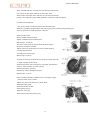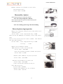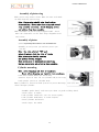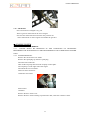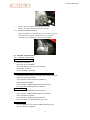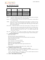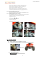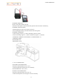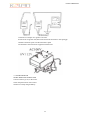
1
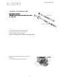
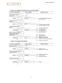
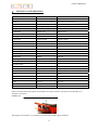
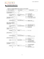
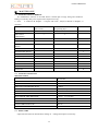
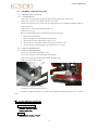
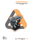
S
E
R
V
I
CEMANUAL
SPORTMODEL
UTI
LI
TYMODEL
c
c
0
V9
T
A
e
k
o
r
t
rS
u
o
F
KOLPIN POWERSPORTS
SECTION 1
CONTENTS
MAINTENANCE INFORMATION
SPECIALIZED TOOLS
SPECIFICATIONS
HARDWARE RATED TORQUE VALUES SUGGESTED
MAINTENACE INTERVALS
MAINTENANCE INFORMATION
1
KOLPIN POWERSPORTS
2
KOLPIN POWERSPORTS
3
KOLPIN POWERSPORTS
4
KOLPIN POWERSPORTS
5
KOLPIN POWERSPORTS
6
KOLPIN POWERSPORTS
7
KOLPIN POWERSPORTS
8
KOLPIN POWERSPORTS
Specifications
item
engine type
pattern
bore* stoke
capacity
compression ratio
rating power& rating running speed
maximum torque
minimum fuel consumption rate
minimum idle stable running speed
lubricating oil brand of engine
lubricating oil pump pattern of
engine
lubrication type of engine
air cleaner type
carburetor type
gasoline brand
ignition type & ignition tilt
rotating direction of engine
spark plug type & gap
valve gap
starting motor type
magneto type
clutch type
gearshift type
speed ratio primary speed ratio
gearshift speed ratio
gearshift device
ending speed ratio
output type
gearshift type
starting type
outer size
net weight of engine
specification
147FMF
single cylinder 4 stroke air cooling tilt 80°horizontal
φ47×49.5
86ml
9.1:1
4.7kw[(7500~8500)r/min]
6.2N.m[(5500~6000)r/min]
367g/kwh
1500±150r/min
SE-15W/40(GB 1121/1995)
inner gear rotator type
pressure splash type
stem plug type
90# unleaded gasoline(GB17930-1999)
CDI electronic ignition 1500r/min 时 15°±1°4000r/min
35°±1°
rotating to left side (view the end of output shaft facing
power)
BPR8HS:0.6~0.7mm
0.02-0.07mm
magneto direct current type
without connecting point type of flywheel
fixed shaft direction pressure and multilayer rubbing fuel
washing pattern
cycle and non cycle pattern
3.722
first gear 3.273
second gear 1.938
third gear 1.350
fourth gear 1.043
cycle and non cycle pattern
3.882
chain drive
left foot operational pattern N-1-2-3-4
electric starting / recoil starting with pedal
461×370×360mm
21.5kg
9
KOLPIN POWERSPORTS
Torque values
Engine
item
nut, cylinder head cover
intake pipe bolt
cam sprocket bolt
adjusting screw, valve
lock nut, clutch
flywheel fixed nut, magneto
drain plug, engine
quantity
4
2
3
2
1
1
1
screw thread dia.mm
6
6
5
5
14
10
12
torque value N.m
8.0-12
9.0-14
8.0-11
7.0-11
38-45
30-38
20-25
other torque value for regular fasteners should refer to the following table, besides
some torque valve for important parts are listed in the above table.
name & screw thread spec
torque value(N.m)
5mm bolt nut
4.5-6.0
6mm bolt nut
8-12
8mm bolt nut
18-25
10mm bolt nut
30-40
12mm bolt nut
35-50
5mm bolt nut
3.5-5
6mm bolt nut
7-11
Specialized tools
tool name
reference chapter
flywheel puller
mounting holder,clutch
10
KOLPIN POWERSPORTS
Maintenance
frequency
items
*
replace
*
**
Schedule
item
period
mileage table km(note 2)
1000km 4000km 8000km
12000km
fuel system
—
I
I
I
spark plug
—
I
I
I
lubricating
yearly
oil, engine
filter mesh, yearly
lubricating
oil
valvegap
R
R
every run 2000km
—
C
C
—
I
I
I
air cleaner
—
C
C
C
idle speed
system,carb
uretor
I
I
I
I
The engine should be repaired within regular repairing time. Before repairing, the
engine should be cleaned.
In the above table, the sense of each sign is followed.
I: Check-up, washing, adjusting, lubricating or replacement C:washing R:
replacement A:adjusting
L:lubricating *: The item needs repairing by service station of KOLPIN. If the user
has specialized tools, repairing parts or repairing ability, he can repair it by himself.
**: For the sake of safety, the item can only be repaired by service station of
KOLPIN POWERSPORTS.
Note:
1. Wash the whole vehicle usually, when running in dusty conditions prior to
servicing.
2. Perform service at mileage or time schedule, whichever comes first.
11
KOLPIN POWERSPORTS
Lubrication system diagram
12
KOLPIN POWERSPORTS
Section 2
Lubrication system
service notice
replacement of lubricating oil
trouble removal
washing of lubricating oil mesh
lubrication system of engine
fuel pump
check-up of lubricating oil
Service notice
General rules
The section mainly introduces washing, check-up and replacement of the lubrication system
and each part in system for engine. When checking up and washing lubrication system, the engine
may be dismantled step by step, but the lubricating oil in engine needs draining before checking
up and washing.
Technology specification
standard value
service limit
engine oil capacity
the capacity of replacing oil is about 0.8L, the
capacity of mantling engine is 0.9L.
Oil pump
radial clearance for inner & outer
rotator
0.15-0.20mm
Oil pump
radial clearance between pump
body and outer rotator
0.02-0.07mm
Oil
shaft-apt clearance
0.10-0.15mm
pump
Troubleshooting
Engine oil consumption excessive
1.engine oil leakage;
2. piston rings worn;
3. intake & output valve guides worn;
Lubrication work badly
1.oil level is too low;
2. oil strainer glogged or worn out;
3. oil pump worn out;
13
KOLPIN POWERSPORTS
4. Transmission shaft oil seal assembled improperly or is damaged.
Engine oil is unclean.
1. Engine oil not changed according to service period table.
2.The screw thread of oil fill hole worn out.
14
KOLPIN POWERSPORTS
Lubrication system of engine
Lubricating system of engine:
Lubricating oil of engine:
The lubricating oil is 15W/40QE grade gasoline
oil and not common oil or other oil when this vehicle
leaves our factory.
The viscosity of engine oil should be used
separately according to different area and
temperature change.The right picture shows the engine
oil brand recommended under different temperatures.
If there is no way to purchase 15W/40QE gasoline oil,
use 10w-40 (5w-40 only used under -10℃) instead.
Engine oil capacity:
The capacity of engine disassembled and
reassembled is 0.9L.
The capacity is 0.8L after draining oil and fill.
Fuel pump flow capacity is 2.2L/min(4000r/min)
Check-up of lubricating oil
Back up motor on the flat ground with main bracket,
check up net oil capacity. If oil level is under the low carved
line, the oil recommended should be made up, and make it
above upper carved line.
The replacement of lubricating oil
When replacing lubricating oil, the engine should be
warmed up and not cool down. Doing such can promise
removing the lubricating oil in crankcase. When replacing,
place a plate under the engine to make oil drop into the plate,
and then unload the drain plug. After finishing oil drain, we
should check up the plug washer in proper, and then assemble
the drain plug.
torque value of oil drain plug: 20-25N.m
Fill 0.8L new lubrication from the refueling spout.
Load the plug of refueling spout, and start the engine,
and then stop the engine after running for 2-3 minutes at the
idle speed. Back up the vehicle, and check the oil level normal
(put the motor vertically), and finally check the leakage
normal.
15
KOLPIN POWERSPORTS
Disassemble oil of
mesh.lubrication
washing
Clean away the mesh, and then put it into right
crankcase body.
mesh
Load the following parts well:
Note: Before making this item, drain off the oil.
Right crankcase cover, kick arm, exhaust
Dismantle oil drain screw, right crankcase and
muffler, clutch operation cable, footwell and clutch
clutch outer cover. Clean ending cover and inner
outer cover.
face of clutch outer with cotton fabric. And
Fill recommended oil into crankcase, and start
dismantle seal cushion of right crankcase and
engine and make it run for 2-3 minutes at the idle
dowel pin.
speed, and then turn off engine, put the motor in
porper, and check the capacity of lubrication. Never
make leakage exist.
Oil pump
Screw off oil drain plug, and drain oil.
Disassemble right crankcase cover.
Disassemble clutch assy and three screws of
oil pump, and then unload the oil pump.
check-up of oil pump
Unload the oil pump cover.
Measure the radial clearance of inner/outer
rotator according to diagram.
service limit:0.20mm
16
KOLPIN POWERSPORTS
Measure the radial clearance
between outer rotator and oil pump body
according to diagram.
service limit:0.12mm
Measure the end surface clearance between rotator and
oil pump. Measure the head face clearance
rotator and oil pump body.
Servicebetween
limit: 0.20mm
service limit:0.20mm
Assemble of oil pump
Load inner/outer rotator. Insert the oil
Assembly of oil pump
pump shaft, and make the flat horizontal
Assemble inner & outer rotator of oil pump. Insert oil
surface of oil pump shaft allignment with
pump shaft and make surface of oil pump alignment
that of inner rotator.
with surface of inner rotator.
Mantle the seal cushion of oil pump cover
Load seal cushion of oil pump and oil pump cap, and
and oil pump cover, and fasten it with screws.
fasten them with screw.
Note: After assembly, oil pump can run normally.
Note: After loading, oil pump can rotate
normally, not appear clipping or sticking.
Setting of oil pump
Assemble order: seal cushion of oil
pump cover, oil pump cover, screw
Set the oil pump with seal cushion,
make oil pump shaft alignment with the
opening on oil pump sprocket shaft. Load the
clutch, right crankcase and muffler.
Adjust clutch well.
Fill oil into crankcase.
17
KOLPIN POWERSPORTS
Section 3
Check-up and adjustment
service notice
idle speed of carburetor
technology requirement
tension for timing chain
spark plug
cylinder pressure
choke lever
drive sprocket
valve clearance
adjustment for clutch
Service notice
General rule
This book introduces check-up and adjustment for all parts of CQ90FMH type engine. At the
same time, it also introduces the technology requirement of adjustment and check-up. For
check-up and washing of lubricating system, refer to second section.
Technology requirement
ignition timing:
recommended spark plug:
clearance for spark plug:
valve clearance:
idle speed:
cylinder compression power
ignition before piston reach the top point 27°/1500rpm
China pattern BPR8HS
0.6-0.7mm
0.02-0.07mm
1500±150rpa
1247kpa±196kpa
18
KOLPIN POWERSPORTS
Spark plug
Take off spark plug cap.
Take off spark plug with barrel spanner.
Wash the dust around spark plug. Central
electrode should be square side, and side
electrode should have a certain thickness,
and check electrode ablated. If spark plug is
damaged obviously or isolator is split, new
spark plug should replaced.If seal cushion of
spark plug has been worn, replace it.
Check up the electrode clearance with
caliber gauge. The electrode clearance of
spark plug is 0.6-0.7mm.
Carefully adjust the clearance, and
then remove the deposited carbon or dust
with spark plug washer or steel silk.
Load spark plug, by hand swirl spark
plug into and screw it tightly, and then screw
it tightly with barrel spanner. And then cover
the spark plug cap.
Choke lever
Check choke lever for moving freely, and
location standard. If obstacle occurs when
moving, drop some drops of lubrication into
flexible shaft. Polish shaft and shaft sheath on
carburetor and wash them and then coat oil on
them.
Valve clearance
Note: adjust valve
clearance when
engine is on cool condition.(temperature is
lower than 35℃)
Disassemble decoration cover and upper
sight hole cover.
Insert decoration cover hole with barrel
spanner, and cover on nut of crankshaft.
Turn magneto flywheel counterclockwise,
and make mark “T” on flywheel alignment
with indicating mark on left front cover. At this
moment, piston should be on the location of
upper stop point of compression play.
19
KOLPIN POWERSPORTS
Take off valve cover.
Insert plug gauge between adjusting
screw and valve pole to check the clearance.
valve clearance: intake valve 0.03mm
venting valve 0.05mm
When adjusting, loosen the nut and then
rotate adjusting screw until caliber gauge
feels light resistance. Then make adjusting
screw stable with valve adjuster, and rotate
lock nut tightly.
Then check up valve clearance.
Finally assemble valve cover, decoration
cover and upper sight hole cover well.
Idle speed of carburetor
Note: after adjusting other item of
engine into regulated range, check and
adjust idle speed of carburetor.
Adjust when engine is warmed up and
running. Back up the motor with main
bracket, and adjust idle speed and screw of
carburetor.
idle speed 1500r/min
Tension for timing chain
Start engine and make it run at the idle
speed, and check up tension for timing chain.
If chain is not tensioned, put motor on
level stand, loosen seal plug, and check up
spring of chain tensioner pole in proper, and
check up whether oil enter inside chain
tensioner comp. If the spring is not effective,
and replace it. If no oil enter inside
tensioner pole, loosen seal bolt, and fill some
oil on it.
After finishing the above checking
work, assemble each part well.
20
KOLPIN POWERSPORTS
Cylinder pressure
Warm up the engine and make engine
flameout, and disassemble spark plug. Load
pressure table and close choke, and make throttle
turning bar open completely. Run starter motor
quickly.
Note: Cycle starter until the number on
pressure table does not go up. The maximum
degree usually reaches after 4-6 times
starting.
cylinder compression power: 1274kpa±196kpa
pressure power is too low:
1. valve adjustment improper
2. cylinder head leaks air
3. seal cushion of compression tester leaks
air
4. piston ring or cylinder worn
pressure power is too high:
1.Deposited carbon exist in combustion
chamber on piston.
Drive sprocket
。Check up whether drive sprocket gear and
driven sprocket gear have excess wearing, if they
are worn excessively, replace them.
Note: Never set new chain on a worn sprocket.
Sprocket and chain must be replaced, as a set to
reduce.
Adjustment of clutch
1. remove decoration cover of right cover of
engine
2. loosen adjusting nut of clutch
3. screw adjusting screw of clutch tightly with
screwdriver, until resistance is felt 1/4 turn.
4. screw adjusting nut of clutch, and torque to
18~25N.m.
21
KOLPIN POWERSPORTS
Section 4
Carburetor
service notice
troubleshooting
discharge of carburetor
valve
float/float needle/jet spout
measure of float height
mounting of valve
mounting of carburetor
adjustment of idle speed adjusting screw
Service notice
General rule
1. Deal with gasoline carefully only in a well ventilated area, and far away from spark and flame.
2. Dismantling all parts of fuel system should pay attention to mounting position of “O”ring.
When assembling again, replace new “O” ring.
3. There is fuel drain screw under float champer, loosen the screw and remove gasoline left in
float bowl
Troubleshooting
Engine may ignite but not start
1.no fuel flow to engine
2.no fuel flow into carburetor
3.too much fuel enter cylinder
4.air cleaner clogged
Mixture air is too rich
1.choke is closed
2.fuel level in carburetor is too high
3. air jet spout of carburetor clogged
4.float is clipped or float needle is sticking open
5.air cleaner is not clean
Mixture air is too lean
1. jet of carburetor clogged
2.breather hole of fuel bowl cover clogged
3. fuel filter clogged
4. fuel in fuel pipe flows badly
5.float needle has troubles
6.Fuel level in carburetor is too low
Idle speed of engine is not stable, speed losing or running badly
1.idle speed adjusts improperly
2. mixture air is too rich
3.mixture air is too lean
22
KOLPIN POWERSPORTS
4.cylinder compression is too low
5. air filter clogged
6. impurity in fuel
7.Fuel is old
Carburetor
disassembly
Close fuel cock, and disconnect fuel
panel. And dismantle choke operation wire.
Loosen oil drain screw of carburetor and drain
fuel in carburetor bowl.
Take off connecting bolt between
carburetor and intake pipe, and diamantle
connecting spring clip washer between
carburetor and air cleaner.
Then take off carburetor cover, and take
out valve plunger piston. And disassemble
carburetor.
Note: Keep away from spark and flame.
Clean up any spills immediately.
Carburetor slide
In lower socket of carburetor slide
disconnect the end of throttle operation wire.
Press down spring of slide when
disassembling.
Disassemble dowel spring of fuel needle,
and then disassemble fuel needle and fuel
needle clip together from bleeding valve.
Check for bleeding valve and fuel needle
surface clean, smooth, scratch or worn.
Float, float needle, jet
Disassemble connecting screw of float
champer cover, and take off float champer
cover. Then take out float arm pin.
23
Disassemble float and
floatPOWERSPORTS
needle
KOLPIN
Check for float needle seat worn. If
necessary, replace new float needle.
Dismantle main jet, jet spout of air bleeder,
idle speed orifice, bleeding shutter and idle
speed screw. And then dismantle air screw
adjustment.
Note: Measure mounting position of
adjustment screw before dismantling air
screw adjustment. Record the cycle number
of dismantling screw. Otherwise, mounting
air screw adjustment will cause unnecessary
troubles.
Then wash hole panel and surface of
carburetor with cleaning solution. After
washing, blow full hole panel with
compression air, and clear away dirt.
Then, assemble idle speed orifice, jet spout
of air bleeder,main jet and idle speed screw
according to the reverse order of
disassembly. Assembly air screw adjustment
according to mounting positon before
disassembly.
opening positon of air screw adjustment:
Screw in place and then return 1-3/4
cycle.
Mounting float,float needle, and then
insert float arm pin.
Measurement of float
height
Measure height of float with height gauge.
20 .0mm If height of float is not correct, and
adjust float height.
Carburetor slide mounting
Mounting clip inner ring groove of fuel
needle. And insert fuel needle into carburetor
slide, and then mounting dowel reed.
24
KOLPIN POWERSPORTS
Then, mounting plunger piston spring
inner throttle operation wire. And connect
operation wire with slide plunger piston
well.
Carburetor mounting
Mounting slide inner carburetor.
Note: make sure socket of slide aligns
with adle speed adjust screw of
carburetor.
Spin end cover of carburetor top
tightly.
After mounting carburetor, adjust free
play of throttle handlebar with adjuster on
throttle operation wire.
free play of throttle handlebar: 2—6m m
Adjustment
of
idle
speed adjustment screw
Spin idle speed adjustment screw
clockwise until it touches screw hole
holder. And then spin counterclockwise to
standard position.
standard position: 1-3/4cycle
Note: If idle speed adjustment screw
and screw hole holder are screwed
tightly, doing such will damage screw
hole holder.
Start engine and make it warm up to work
temperature. Adjust adjusting screw of
bleeding shutter, and make idle speed
reach 1500r/min.
Adjusting idle speed adjusting screw
slightly, and make it reach running speed,
for example, when over 1500r/min, and
adjusting valve adjustment screw to make
idle speed reach 1500r/min.
25
KOLPIN POWERSPORTS
Section 5
Disassembly and assembly of engine
service notice
disassembly of engine
assembly of engine
Service notice
General rule
When disassembly and assembly of engine, back up the motor with main stand, if
disassembly and assembly on lift plat, fix front wheel and make maintenace for the
following parts and comp after dismantling engine from the frame.
·cranklever and piston
·recoil starting unit
·transmission unit
·cam chain tensioner
·intake and oulet valve
Skill specification
engine weight:2lkg
oil capacity: filling volume is0.8L after disassembly.
Rating torque:
hang bolt of engine:
bolt of transmission sprocket:
pedal bolt:
exhaust pipe bolt:
39—49N .m
39—45N. m
35 45N.m
8—12N.m
26
KOLPIN POWERSPORTS
Disassembly of engine
Drain off lubrication from engine.
Diamantle exhaust pipe fixed nut and
muffler fixed nut, and take off exhaust
muffler.
Take off spark plug cap, and move
away high voltage wire from fixed clip
of high voltage wire.
Dismantle clutch operation wire.
Disassemble and rear cover of left
crankcase.
Loosen rear axle nut and
transmission chain adjuster, and then
dismantle spline cushion, drive
sprocket and driven chain.
Place a jack or other backing
equipment adjustable under engine.
27
KOLPIN POWERSPORTS
Disconnect magneto and gear position switch
and main cable and connecting wire. Disassemble
starting motor wire.
Disassemble the two hang bolt of engine, and
then disassemble engine.
Note: Remove engine slowly.
Assembly of engine
The assembly order of engine is basically the reverse
order of disassembly process.
Note: Check correct connecting of all wires
Adjust free play of throttle cable well
Adjust the free play of clutch wire.
Adjust the sag of driven chain.
fill recommended oil into crankcase until oil
reaches proper positon.
rating torque:
drive sprocket bolt:39-45N .m
pedal fixed bolt:39M5N.m
hang bolt of engine:39~49N .m
Mounting of muffler
Firstly fasten the muffler on cylinder head and frame
with two nuts and frame fixed nut of muffler, but not
screw them tightly.
After feeling seal of cylinder head outlet mouth
is good, screw two fixed nuts of exhaust pipe tightly,
and then screw fixed nut between muffler and frame.
Note: After assembly, air leakage can not be
allowed on exhaust spout.
rating torque:
fix nut of exhaust pipe:8-12N.m
fix bolt of muffler:39-49N.m
28
KOLPIN POWERSPORTS
Cylinder head and valve
29
KOLPIN POWERSPORTS
Chapter 6
Cylinder head and valve
service notice
check-up of camshaft
rubbing of valve holder
troubleshooting
check-up of cylinder head
assembly of cylinder head
disassembly of cylinder head
check-up of valve spring
assembly of cylinder head
disassembly of cylinder head check-up of valve and valve guide pipe assembly ofcylinder head
check-up of swing arm and swing arm shaft
replacement of valve guige pipe
Service notice
The section introduces the maintenance and check of the part: Cylinder head, Valve, Camshaft
and rocker shaft. Above-mentioned section, it can be implemented but not tear down the engine.
Camshaft and rocker shaft lubrication oil passes from the oil groove, so it must be guaranteed
the oil groove keep free.
When assembled, supramoly lubricant should be coated on bearing of the camshaft as basic
lubricant.
When installed the Cylinder head, it should be installed the new coil form obturating ring and
gasket seal.
Technology specification
Items
Reference value (mm)
service limits mm
Air-in
26.641
26.25
air-out
26.408
26.02
Oil clearing dist.
0.010-0.025
0.1
lateral clearance dist.
0.004-0.036
0.1
Rocker hole
inner diameter
φ10.000-φ10.005
φ10.10
Rocker shaft
outer diameter
φ9.978-φ9.987
φ9.91
valve spring
unbraced
length
outer layer
35.5
34.0
internal layer
32.8
31.2
Camshaft
Cam rise
valve dist.
(air-in/air-out)
0.03-0.05
—
Valve
valve spindle
outer diameter
air-in
φ4.970-φ4.985
φ4.92
air-out
φ4.955-φ4.970
φ4.92
air-in
φ5.000-φ5.012
φ5.03
air-out
φ5.000-φ5.012
φ5.03
air-in
0.015-0.042
0.08
air-out
0.030-0.050
0.10
Valve seating width
1.0
1.6
flatness
—
0.05
valve
tube
inner diameter
Dist.
Betw.
Valve spindle
and tube
Cylinder head
30
KOLPIN POWERSPORTS
Troubleshooting
Black smoke in exhaust air
1. Valve seat worn out
2. cylinder head gasket is leaking
3. piston ring end gap is outside of specification
Overloud Noise
1. The adjustment of valve is not correct
2. Valve gets stuck or valve spring broken
3. Camshaft and rocker shaft gets wear and tear
4. Timing chain is too long
5. Timing not set to specification
6. Tensioner of timing chain gets wear and tear or damage
7. Timing chain wheel tooth gets wear and tear
Pressure in cylinder is below normal
1.Valve
--Adjustment of valve distance is not correct
--sealing of valve is not good
--Timing distribution is not correct
--Valve spring is cracking
2. Cylinder head
--The spark plug is not tight
-- Cylinder head gasket is leaking or damaged
-- Cylinder head has crack and pinhole porosity
3. Cylinder and piston
-- Piston ring end gap is relative oversize and
cracking
--Piston has crack and is damaged
--Cylinder diameter is oversize or has pinhole
porosity
Cylinder head disassembling
Remove the inspection plate and ornamental lid.
Then turn the fly wheel in an anticlockwise
direction and make the mark ‘T’ align with that of
on the left forward lid.
Remove the exhaust muffler;
Remove the spark plug cap
Remove the suction tube and connect the bolt
31
KOLPIN POWERSPORTS
Loose the stay bolt on the right lid of the
cylinder head. Beat the bolt and jack up the
left lid. And remove the bolt and left lid.
Remove two bolt s from the right lid of
the cylinder head;
Remove the bolt and cylinder head lid;
Remove the driven sprocket bolt, and
take off the driven sprocket bolt;
Take off the cylinder head;
Clean the upper, lower, left, right part of
the cylinder head and the junction surface of
the carburetor;
Remove the obturating ring, interfacing,
gland bush of the cylinder head, pin stop.
Clean the upper face of cylinder block.
Cylinder head disassembly
Remove the intake and exhaust
valve-chamber cover and the O-ring
closed-coil;
Screw in an 8mm bolt on the screwed
end of the rocker shaft, then pull the rocker
shaft from the right side of the cylinder head;
And remove the rocker shaft.
32
KOLPIN POWERSPORTS
Make cam lobe align with cylinder head
opening and remove camshaft from cylinder
head.
Compress the valve spring wiht the valve
spring compresser, then loose the valve spring
compressor, and take off the valve spring seat,
valve spring and valve.
(ps In order to avoid tension set of the valve
swing, do not compress the valve spring
excessively when disassembled.)
Clean the carbon in the cylinder head totally;
Clean the surface of the cylinder head;
(Ps. Do not damage the sealing face of the
cylinder head.
If you immerse the valve guide in the
solvent, it will be damaged.)
Check-up of rocker arm pivot
Check rocker arm for wear,damage or
clogged oilhole.
Measure inner diameter of rocker arm.
service limit:
Service limit:φ10.10mm
33
KOLPIN POWERSPORTS
Check rocker shaft for wear or damage. Measure
outer diameter with micrometer.
service limit:φ9.9mm
Check of the camshaft
Check each camshaft bearings whether the distance
is over size or damaged. If the bearings have noise or
oversize distance, it will be replaced.
Check the lift range of the intake and exhaust cam.
Check whether it is damaged or worn away.
Service limits: air-in: 26.25mm ;air-out: 26.02mm
Check of the cylinder head
Check the spark plug and the valve seating whether
there is a crack;
Check the cylinder head whether it becomes
deformed, and check the flatness of the cylinder head by
knife edge ruler or proof stick.
Service limits: 0.05mm
Check the valve spring
Measure the free length of the valve spring;
Service limits:
Intake valve: inner spring: 31.0mm
Outsider spring: 34.0mm
Exhaust valve inner spring: 31.2mm
Outsider spring: 34.0mm
34
KOLPIN POWERSPORTS
Check the valve and valve guide
Check each valve whether there is a warp or burn or an
abnormal abrasion on the top of the valve rod;
Check the movement situation of the valve in the valve guide;
Measure the outside diameter of each valve rod.
Service limits: intake/ exhaust: φ4.92mm
Measure the inside diameter of each valve tube by inside
micrometer or special measure tools.
Service limits: φ5 .03mm
Finally count the distance between the valve rod and valve
guide.
Service limits: 0.1mm
Note: Before measuring the inside diameter of valve guide,
remove carbon residue.
If it needs to replace the valve guide, the surface of valve seat
should be polished.
Change the valve guide
Fix the cylinder head, pull out the valve guide from valve
hole by valve guide removal tools.
Note: Do not wear away the cylinder when removing the
valve guide.
Install new valve guide and O-ring into the cylinder head.
Then ream on the new installed valve guide.
Note: When chambering, it should be coated cutting oil on
the cutter knife. And it should be turned when installing and
removing the cutting knife.
Finally clean the cylinder head by detergents. And clear out
all the borings accumulating on cylinder head by compressed air.
35
KOLPIN POWERSPORTS
Polished dressing of valve seat
First clear out all the carbon in the intake and exhaust valve seat.
Apply polishing compound to valve and insert into head.
Turn with rubber coated head to clean valve seat.
Note: Do not let the detergent enter into the place between the
valve rod and jumbo valve guide. After polished dressing, clear
away the detergent completely. Then coat a layer of engine
lubricant on the valve sealing face and valve seat.
Take down valve and check the valve-face width.
Service limits: 1.6mm
Note: If the valve-face is crude or non-uniform corrosion
or it can not contact the valve seat, the valve should be replaced.
Measure the valve seating face width.
Service limits: 1.6mm
If the valve seat is too wide or too narrow or has a dent,
it should be maintain to achieve correct good seal.
Valve seating iron knife
Three iron knives with different angles.
Use prescribed iron knife to scrape when polish the
valve seat.
First, excise the crude or irregular place of the valve
seat by the 45 iron knife.
Note: When changed the valve guide, it also needs to scrape
the valve seat by the 45 iron cutter knife
Second, scrape one forth of the upper links of the
valve face by the 32 reamer.
Third, scrape one forth of the bottom zones of the
valve seat by 60 iron knife.
Finally, process the valve seat face proficiently to
achieve real height.
The standard width of the face: 1.0mm
Check of the relative position between valve seat and valve
Coat a stamp-pad ink upon the valve seat.
And turn the valve. Then pull out the valve to observe
36
KOLPIN POWERSPORTS
whether the contact face is correct and well.
Pay attention to the contact between valve and
valve seating whether it is well or not.
It is a very important factor for the sealing performance
of the engine.
If valve surface is too high, it can be lowered by the 32
iron sharpener.
If valve surface is too low, it can be lifted by the 60 iron
sharpener.
Finally process the iron sharpener by the 45
cutting tools until the width of valve seating surface is
achieve that of the regulations.
After processed the valve seating, coat a layer of abrasive
upon it.
Then load it into the valve and grind it by rubber head
grinding tools.
After doing it, clean all the residual abrasive on the
cylinder head,
valve, valve seating, and valve tube.
Equipment of the cylinder head
First of all, cover oil shield on the valve guide and coat
the supramoly
lubricant on each valve rod. Then insert valve into the
valve tube.
Fit valve spring and spring seat.
Note: In order to avoid damage of the oil shied, turn
the valve slowly when inserted.
Second, depress valve spring by valve detacher. After
that, insert valve cullet on the valve spring seat.
Note: In order to avoid the spring causing tension set,
do not compact it excessively.
37
KOLPIN POWERSPORTS
Insert camshaft and turn it to make the cam lift range downwards.
Coat a layer of thin engine lubricant on the rocker shaft.
Install rocker and rocker shaft. And turn one end with a thread out.
Change a new right lid cylinder head gland bush. And then install the right lid.
Cylinder head Installment
Turn the fly wheel to make the piston reach the dead center.
Install new cylinder head gland bush, seal packing ring, liner bushing, and positioning pin.
Note: Do not let dust and dreg fall into crankcase.
Install cylinder head.
Install cylinder head gland bush.
Tighten cylinder head and stabilize bolt.
Rated torque: 10-14N.m
The mark ‘arrow head’ of cylinder head should be align to
the below of it When installed.
Tighten acorn nut and hexagon nut on the cylinder head by
crossing angle direction.
It includes two or three steps.
Rated torque: 8-12N.m
Turn the fly wheel in an anticlockwise direction to make the mark
‘T’ align with that on the left lid.
Install timing chain on the timing driven sprocket, and make the
mark ‘O’ align with that of on the cylinder.
Install timing driven sprocket.
Stabilize fly wheel, and tighten the bolt.
Rated torque: 8-11N.m
Install cylinder head left lid. Make sure it’s raised place aligns
with the socket of the cylinder.
Tighten stay bolt on the left lid of cylinder head.
Install the intake guide.
Install the exhaust muffler.
Install spark plug cap.
Adjust the valve gap.
Install valve lid and seal packing ring.
38
KOLPIN POWERSPORTS
Cylinder & piston
35
KOLPIN POWERSPORTS
Section 7
Cylinder & piston
service notice
troubleshooting
disassembly of cylinder
cylinder inspectioin
piston ring mounting
disassembly of piston
piston mounting
inspection of piston & piston ring
cylinder mounting
Service notice
General rule:
It is unnecessary to remove engine for maintaining and checking cylinder and
piston.
Lubrication for camshaft and swing arm is the lubricating oil filled into fuel panel
inner cylinder.So fuel panel can not been clogged.
Technology specification
item
standard value (mm)
cylinder inner diameter
cylinder
piston,
piston ring
and piston
pin
φ50.005—φ50.015
Service limit (mm)
φ50.05
taper
—
0.10
roundness
—
0.10
top flatness
—
0.10
skirt section diameter of
piston
φ49.975—φ49.995
φ49.90
inner diameter of piston
pin hole
φ13.002—φ13.008
φ13.05
clearance between piston
pin and piston pin hole
0.002—0.014
0.075
cutter
clearance of
piston ring
top ring &
second ring
0.10—0.30
0.5
fuel ring
0.20—0.90
1.1
clearance
between
piston ring
and
ring
socket
top ring
0.015—0.050
0.12
second ring
0.010—0.045
0.15
0.010—0.045
0.15
clearance
cylinder piston
between
35
KOLPIN POWERSPORTS
small end
of tie bar
outer diameter of piston
pin
φ12.994—φ13.000
φ12.980
inner diameter
φ13.016—φ13.034
φ13.06
clearance between tie rod
and piston pin
0.016—0.040
0.08
Troubleshooting
Overheat
1. too much deposited carbon
in piston or combustion chamber
compression power low or unstable
1.Cylinder or piston ring worn
Knocking or abnormal noise
1.piston or cylinder worn
excess black smoke exhausted
1. cylinder or piston ring
worn
2. too much deposited carbon
in piston or combustion chamber
2. incorrect mounting of
piston ring
3. piston or cylinder wall
sliding or scuffing
Disassembly of cylinder
Disassemble cylinder head
(refer to sixth chapter)
Disassemble pin shaft of guide rolling
wheel and guide rolling wheel.
Disassemble mounting bolt of cylinder
Note: Timing spocket chain never drop
into crankcase when disassemble.
Dismantle cylinder
Disassemble rectangle seal washer,
cylinder cushion and dowel pin.
Clean bottom face of cylinder body and jointing face between cylinder body and
crankcase.
Cylinder inspection
Check inner wall of cylinder for wear or damaging.
Note: avoid damaging cylinder end face when doing this work.
Measure inner diameter of cylinder, three positions should be measured. They are
top section, middle section and bottom section of piston play. And each position
should be measured from two directioin with vertical angle.
service limit:φ50.05mm
36
KOLPIN POWERSPORTS
Measure flatness of cylinder top with ruler
and thickness ruler.
service limit:0.05mm
Disassembly of piston
Disassemble piston pin circlip with clamper.
Note: never drop circlip into crankcase
Press out piston pin from piston and disassemble piston.
Disassemble piston ring.
Note: never damage piston ring when disassembling.
Piston & piston ring inspection
Measure the clearance between piston ring socket with
thickness ruler.
service limit: first ring/second ring 0.12mm
Check piston for damaging or cracking; piston ring socket
worn.
Insert every piston ring into inner cylinder, then measure
the shutting clearance.
service limit: first ring/second ring 0.15mm
oil ring
1.1mm
Measure outer diameter around
10mm position on skirt section bottom.
service limit:φ46.90mm
Count the clearance between cylinder and piston.
service limit:0.15mm
Measure inner diameter of piston pin hole.
service limit:φ13.05mm
Measure outer diameter of piston pin.
service limit:φ12.98mm
Count the distance between piston pin
hole and piston pin.
service limit:0.075mm
Measure hole diameter of tie rod head.
service limit:φ13.06
37
KOLPIN POWERSPORTS
Assembly of piston ring
Wash piston ring socket clean. Make the face with mark
up when mounting piston ring.
Note: Piston ring should spin freely after
disassembling. Never make first ring and second
ring assembly reversely. Avoid damaging piston
and piston ring when assembly.
Make clearance of piston ring staggered 120°,never
make the clearances of all fuel rings alignment with
each other.
Assembly of piston
Spread supramoly lubrication in tie rod head hole.
Assembly piston,piston pin and new piston pin
circlip.
Note: the side printed “IN”mark
makes alignment with the side of intake
Make piston pin circlip opening
and piston citting stagger.
When piston pin is disassembled each time,
Replace new piston pin circlip when assembly.
Cylinder mounting
Note: never damaging end face of crankcase.
Never allow dropping any impurity into crankcase.
Load seal cushion,dowel pin and O-ring.
Spread a layer of thin oil on cylinder and piston ring.
Load upright piston on cylinder body.
When cylinder is located on half positon of piston mounting. It is to load timing
chain through cylinder.
Assemble guide wheel, and screw pin shaft of guide rolling wheel.
rated torque:9—14N.m
Load cylinder fixed bolt, but not screw tightly.
Load cylinder head(refer to sixth chapter)
Screw cylinder fixed bolt.
rated torque:10—14N.m
38
KOLPIN POWERSPORTS
Chapter 8
Clutch
service notice
troubleshooting
disassembly of right crankcase cover
disassembly,check-up and assembly for clutch
assembly of right crankcase cover
Service notice
General rule
For maintenance of clutch and gearshift operation arm, it is unnecessary to discharge
engine.
If gearshift fork, gearshift drum and transmission system need repairing and
maintenace, dismantle engine and crankshaft.
Rating torque:
Right crankcase cover fasten bolt 8-12N.M; Clutch round nut 38-45N.M; Gearshift drum
fasten bolt 14-20N.M
Technology specification
item
primary
gear
clutch
shaft
drive
Standard value(mm) Serivice limit(mm)
inner diameter
φ21.000—φ
21.021
φ21.05
19.10
17.50
friction
piece
thickness of clutch
3.45—3.55
3.00
clutch board flat
—
0.2
φ21.930—φ
21.021
φ21.05
free
lenth
spring
of
outer diameter
sheath
Troubleshooting
clutch slipped
1.no free play
2.clutch friction piece worn
3. elastic force of clutch spring is not enough
clutch can not declutch
1. clutch piece bent
39
KOLPIN POWERSPORTS
force pulling occurs when clutch declutch
1. outer cover groove of clutch has burr.
2.gearshift fork bent
3. gearshift rod bent
4.Dowel board of gearshift drum cracked
Disassembly of right crankcase cover
。Drain off engine oil.
Dismantle fasten bolt and cover of right crankcase cover.
Clutch
Diaassembly, check-up and assembly for clutch
Disassembly for dowel stand board.
Dismantle decoration cover.
Dismantle lock nut,washer,o-ring, and then dismantle dowel stand board.
Disassembly for clutch
Take off lift board, srping of fuel bushing, fuel bushing, operation arm.
Dismantle screw on clutch cover, and take off clutch end cover and seal cushion.
Dismantle stopper washer on round nut with opener.
Dismantle round nut, stopper washer and disc washer with lock nut spanner.
Take off clutch, drive gear wheel, shaft sheath and
Seat washer.
40
KOLPIN POWERSPORTS
]Disassemble
clutch
Take off shock absorber spring of clutch.
Take off elastic circlip.
Dismantle clutch piece/board, drive gear wheel outer.
Inspection for clutch spring.
Measure free lenth of clutch spring.
standard value:19.1mm
service limit:17.5mm
Inspection for friction plate of clutch
If friction plate of clutch is scratched or
defaded, it should been replaced.
Measure thickness of each friction plate.
service limit:3.0mm
41
KOLPIN POWERSPORTS
Flatness of up & down board inspection
Check flatness of up & down board.
service limit:
up & down board 0.02mm
Inspection for drive gear wheel/shaft sheath
Check the above parts for worn or damaged.
Measure inner diameter of gear wheel and outer
diameter of shaft sheath.
service limit:inner diameter of gear wheelφ21.05mm
outer diameter of shaft sheath φ20.90mm
Assembly of clutch
Cover crankshaft with drive gear seat washer.
Cover crankshaft with drive gear.
Load drive gear bushing.
Spin drive gear, and make
sure assembly of clutch is correct.
Drive gear can spin freely towards
counterclockwise, but not towards clockwise.
Assemble disc washer, stopper washer and round nut.
Note: when assembling disc washer, make “OUTSIDE”on washer towards outside.
Load clutch comp.
Load stopper wahser.
Load round nut and screw it tightly.
rating torque:38—45N.m
Bend one side of stopper washer and
screw round nut tightly.
Load seal cushion of clutch end cover, clutch end cover, fuel bushing,spring, fuel
pipe one by one.
42
KOLPIN POWERSPORTS
Assembly for right crankcase cover.
Assemble dowel pin and new seal cushion of right crankcase.
Assemble right crankcase cover according to the reverse order of disassembly. Fill
proper 15/W40QE grade gasoline oil into crankcase.
Load exhaust muffler.
Adjust clutch well.(refer to third chapter)
43
KOLPIN POWERSPORTS
Chapter 9
Magneto
service notice
disassembly of left front cover
disassembly of magneto
assembly of magneto
Service notice
General rule
This chapter introduces disassembly and assembly of engine, only dismantle left front cover, but
unnecessary to dismantle left rear cover, so magneto disassembly is finished.
Rating torque
flywheel fasten nut
30—38N.m
Disassembly of left front cover
dismantle left rear cover
Disconnect the connecting end between magneto
and main cable.
Dismantle left front cover.
44
KOLPIN POWERSPORTS
Disassembly of magneto
Fix flywheel rotator with fixed fork.
Dismantle flywheel fixed nut.
Fix flywheel rotator.
Pull out magneto flywheel with flywheel.
Dismantle two press wire inner left front cover
and transducer.
Dismantle two fixed bolt of stator and
Take out stator comp.
Assembly of magneto
Assembly magneto stator comp inner left front cover.
The order of assembly magneto is the reaverse
order of disassembly.
Note: make woodruff key on crankshaft alignment
with magneto flywheel socket.
Screw flywheel fix nut tightly
according to regulated torque.
Torque value: 30—38N.m
Assembly dowel pin and new seal cushion of left front cover on left crankcase.
Assembly left front cover, and screw left front cover tightly, then dismantle
transmission drive sprocket and left rear cover, and finally fasten bolt.
Connect the inserting end between magneto and main cable.
45
KOLPIN POWERSPORTS
Chapter 10
crankshaft, transmission,
Crankcase,
starting device
service notice
troubleshooting
decomposing of crankcase
disassembly of crankshaft
assembly of starting motor
disassembly of transmission shaft
assembly of transmission shaft
assembly of crankcase
Service notice
General rule
This section introduces disassembly of speedshift, crankshaft and starting structure. When doing
the above work, firstly separate crankcase. For the disassembly of other parts of engine, it should
be done before separating crankcase. The operation is followed before separating crankcase:
disassembly of cylinder head, disassembly of cylinder/piston, disassembly of cluth, oil pump,
disassembly of magneto.
Technology specification
item
Standard
(mm)
value
Service
(mm)
inner diameter of tie rod head
φ 13.016 — φ
13.034
φ13.06
shaft direction
0.10—0.35
0.60
diameter
direction
0.00—0.012
0.05
outer diameter of main axle
φ 16.983 — φ
16.994
φ16.94
outer diameter of counter axle
φ 19.959 — φ
19.980
φ19.94
crankshaft
clearance of tie
rod big end
transmission shaft
46
limit
KOLPIN POWERSPORTS
Troubleshooting
crankshaft noise
1. bearing of tie rod big end worn
2. tie rod deformed
3.crankshaft bearing worn
4.piston pin hole worn
5. piston pin worn
6. tie rod small head hole worn
Disassembly of crankcase
Dismantle engine.(fifth chapter)
Dismantle cylinder head, cylinder and
piston.(sixth and seventh chapter)
Dismantle right cover, clutch,
transmission shaft and oil pump.(eighth chapter)
Dismantle left rear cover,
left front cover, flywheel, transmission driven
sprocket and cover board.(ninth and tenth chapter)
Dismantle tension wheel, timing sprocket, and dismantle fasten bolt of crankcase.
47
KOLPIN POWERSPORTS
And put engine on work plat, right side of engine faces up.
And then dismantle fasten bolt of crankcase.
Separate left and right body of crankcase.
Dismantle dowel pin and crankcase seal cushion.
Wash left and right crankcase, and make inside and outside end
face down.
Disassembly of crankshaft
Take out crankshaft comp from left crankcase
Dismantle main and coumter axle.
Crankshaft inspection
Put crankshaft on V pattern icon.
Measure diameter direction jumping of crankshaft with dial indicator. Actual jumping
number of crankshaft is 1/2 of total read number.
service limit:0.10mm
48
KOLPIN POWERSPORTS
Measure diameter direction clearance of
tie rod big head on two direction
with vertical angle.
service limit:0.05mm
Measure shaft direction clearance of
tie rod big head with thickness ruler.
service limit:0.60mm
Spin bearing by hand, if noise appears
when bearing running, or free play is too large, replace the bearing.
Measure free play of bearing with
dial indicator.
service limit:shaft direction 0.10mm
diameter direction 0.05mm
49
KOLPIN POWERSPORTS
Disassembly of starting montor
Get starting motor down once.disassembling
mounting bolts.
Check-up for starting motor
Check if gear face of starting motor is damaged much.
Transmission shaft
Dismantle mainshaft and countershaft drum together,
then decompose gearshif
Transmission shaft inspection
Check for each gear wheel worn or
damaged, If necessary,replace it. Check for
transmission paw of each gear wheel worn.
Measure ourter diameter of transmission
main axle and counter axle.
service limit:main axle φ16.94mm
counter axle φ19.94mm
50
KOLPIN POWERSPORTS
Assembly of transmission shaft
Note:Before assembly,
15W/40QE grade engine oil should be coated
on each part.
First of all, assemble transmission axle and
gear wheel, pay attention to the mouning
position of spline washer and circlip.
Note: The circlip must be mounted on the right position.
Make main & counter axle comp drum assemble
the whole,
and then assemble it into left crankcase.
51
KOLPIN POWERSPORTS
Assembly of crankcase
Remove impurity and remaining cushion on connecting
side of crankcase. Check for connecting
side of left & right crankcase worn.
Assemble new seal cushion and dowel pin.
Snapped down right crankcase. Turn over right crankcase.
Assemble crankcase screw and screw it tightly.
Note: When assembly, washer must be mounted on the right
position.
Assemble and screw fasten bolt of crankcase. Assemble timing chain
on timing drive sprocket, load tension wheel, gearshift drum dowel
bolt and washer, and then assemble contact pressure board and
bolt of gear position switch, connect the plug head of main cable wire
and gear position wire.
52
KOLPIN POWERSPORTS
SECTION 11
Judge the trouble
hard starting
Loss power
engine runs sluggish (especially in low speed and idling)
engine runs sluggish (high speed)
53
KOLPIN POWERSPORTS
54
KOLPIN POWERSPORTS
55
KOLPIN POWERSPORTS
Ⅰ. TECHNICAL INFORMATION
ATV TYPE
70ATV
90ATV
ENGINE
TYPE
Air-cooled、four-stroked
Air-cooled、four-stroked
Displacement
72ml
86ml
Bore
47×41.4mm
47×49.5mm
Compression
8.8:1
8.5:1
Carburetion
Plunger type
Plunger type
Ignition
C.D.I
C.D.I
Starting
Electric
Electric
Lubrication
Pressure splash
Pressure splash
Oil tank capacity
1.0L
1.0L
Transmission
Chain drive
Chain drive
Overall length
1350 mm
1350 mm
Overall width
680 mm
680 mm
Overall high
810 mm
810 mm
Wheel base
920mm
920 mm
Dry weight
70kg
90kg
Fuel tank capacity
4.0L
4.0L
Front
Double wishbone
Double wishbone
Rear
Single damper
Single damper
Front
Drum
Drum
Rear
Disk
Disk
Front
16×8-7
16×8-7
Rear
16×8-7
16×8-7
COLORING
Red/Green
Red/Green
and
stroke
CHASSIS
SUSPENSION
BRAKES
TIRE
Please record the frame and engine serial numbers for future reference. The frame serial Number(1) is
stamped on the frame.
FRAME NO.
The engine serial number (2) is stamped on the left side of THE engine crankcase/
56
KOLPIN POWERSPORTS
ENGINE NO.
ENGINE
70/90ATV
Cylinder head nut
1.3-1.5kg-m
Spark plug
1.5-2.0kg-m
Cylinder head bolt
1.4-2.0kg-m
Alternator bolt
3.5-4.0kg-m
FRAME
70/90ATV
Handlebar upper holder bolt
2.0-2.2 kgf-m
Steering shaft nut
4.5-5.0 kgf-m
Steering shaft bushing holder nut
2.0-2.2 kgf-m
Wheel rim bolt
3.5-4.0 kgf-m
Tie rod lock nut
3.0-3.5 kgf-m
Knuckle nut
3.5-4.0 kgf-m
Handlebar lower holder nut
4.5-5.0 kgf-m
Front wheel bolt
3.5-4.0 kgf-m
Front axle nut
4.0-4.5 kgf-m
Rear axle nut
4.5-5.0 kgf-m
Rear wheel bolt
3.5-4.0 kgf-m
Exhaust muffler mounting bolt
0.7-1.0 kgf-m
Engine hanger bolt
2.0-2.3 kgf-m
Drive sprocket 19T
4.5-5.0kgf-m
57
KOLPIN POWERSPORTS
Ⅱ.
TROUBLINESHOOTING
58
KOLPIN POWERSPORTS
59
KOLPIN POWERSPORTS
Ⅲ.
MAINTENANCE
3.1
MAINTENANCE SCHEDULE
The maintenance intervals in the table below is based upon average riding and conditions.
Riding in unusually dusty areas require more frequent servcing .
C: clean
L: Lubricate R: Replace I: Inspect and Clean , Adjust, Lubricate or Replace, if
necessary
INITIAL SERVICE
(First week)
REGULAR SERVICE(Every
30 operating days)
FUEL LINE
I
THUOTTLE
OPERATION
I
I
AIR CLEANER
C
SPARK PLUG
I
CARBURETOR
SPEED
EVERYYEAR
IDLE
DRIVE CHAIN
I
I
L,I
L,I
BRAKE SHOE WEAR
I
BRAKE SYSTEM
I
I
NUT, BOLT,FASTENER
I
I
WHEEL
I
I
STEERING SYSTEM
I
SUSPENSION SYSTEM
I
C.V.T.AIR FILTER
C
GEAR OIL
R
3.2 MAINTENANCE DATA
SPECIFICATION
70 / 90 ATV
SPARK PLUG GAP
0.7-0.8mm
RECOMMENDED SPARK PLUGS
NGK BPR8HS
THROTTLE LEVER FREE PLAY
5-10mm
IDLE SPEED
1800V±100rpm
BRAKE LEVER FREE PLAY
15-20mm
DRIVE CHAIN SLACK
10-20mm
FRONT/REAR TIRE PRESSURE
2-10 psi
TOE – IN
0-10 mm
ENGINE OIL
SAE10W – 40
GEAR LUBRICATION OIL
SEA 90
BATTERY
12V-5Ah
3.3
FUEL TUBE
Inspect the fuel lines for deterioration, damage or
60
(0.15-0.7bar)
leakage and replace if necessary.
KOLPIN POWERSPORTS
3.4
THROTTLE OPERATION
Inspect for smooth throttle lever full opening and automatic full closing in all steering
positions.
Inspect if there is no deterioration, damage or kicking in the throttle cable, replace it if
necessary.
Check the throttle lever, free play is 5-10mm at the tip.Of the throttle lever.
Disconnect the throttle cable at the upper end.
Lubricate the cable to prevent premature wear.
3.5
3.6
THROTTLE CABLE ADJUSTMENT
Slide the rubber cap of the adjuster off the throttle housing, loosen the lock nut and adjuster
the free play of the throttle lever by turning the adjuster on the throttle housing. Inspect the
free play of the throttle lever.
AIR CLEANER
Unscrew the air cleaner cover screws.
Pull out the air filter element from the air cleaner case.
Wash the element in non-flammable solvent, squeeze out the solvent thoroughly. Let it dry.
Soak the filer element in air filter oil and then squeeze out the excess oil.
Install the element into air cleaner carefully.
61
KOLPIN POWERSPORTS
3.7
SPARK PLUG
The spark plug located at the front of the engine.
Disconnect the spark plug cap and unscrew the spark plug.
Check the spark plug electrodes for wear out.
Install a new spark plug if the electrodes and insulator tip appear unusually fouled or burned.
The spark plug gap must be 0.7-0.8mm
With the sealing washer attached, apply cupper grease,and thread the spark plug in by hand to prevent cross
threading.
Tighten the spark plug with 1.5-2kg-m
3.8
IDLE SPEED
Connect a engine speed meter.
Warm up the engine, 10 minutes are enough.
Turn the idle-speed adjust screw on the carburetor to obtain the idle speed. “Turn in” (clockwise) will get
higher speed. “Turn out” (counter clockwise) will result in lower speed.
3.9
DRIVE CHAIN
Inspect the chain slack. The standard is 10-25mm.
Adjust the chain slack. (in the rear fork)
Loose the lock bolts (4 PCS) then adjust the drive Chain slack by turning the adjustment nut.
Tighten the our lock bolts.
Apply chain lubricant to lubricate the drive chain.
When the drive chain is very dirty, it should be removed, cleaned and lubricated with chain
specific grease.
Clean the drive chain with kerosene and wipe it dry, and apply the lubrican.
Inspect the drive chain for possible wear or damage.
Replace the chain, if it is worn excessively or damaged.
62
KOLPIN POWERSPORTS
Inspect the drive sprocket (13T), if the teeth are worn or damaged, replace it.
Inspect the rubber sleeve.
If the rubber sleeve are worn or damaged, replace it.
3.10
BRAKE SYSTEM
Inspect the front brake lever and cable for excessive free play or damage. Replace or repair if
necessary.
Measure the free of the brake cable at the end of the brake lever .the standard free play is
15~25mm.
Inspect the rear brake lever for excessive free play or damage.
Replace or repair if necessary.
3.11
WHEELS AND TIRES
Inspect the tire surfaces for cuts, nails or other sharp objects. Check the pressure at cold tire
condition. The standard of tire pressure is. 70/90ATV: 3-6psi.
63
KOLPIN POWERSPORTS
3.12
STEERING SYSTEM
Check the free play of the steering shaft with the front wheels, steering straight the tie-rod,
knuckle bushing and ball joint.
3.13
TOE-IN
Park the vehicle on level ground and the front wheels facing straight ahead.
Mark the centers of the tires to indicate the axle center height.
Measure the distance between the marks.
Carefully move the vehicle back, let the wheels have turned 180°,so the marks on the tires
are aligned with the axle center height.
Measure the distance between the marks.
Calceolate the difference in the front and rear measurements, Toe-in:0-10mm.
If the toe-in is out of seandard, adjust it by changing the length of the tie-rods equally by
turning the rye-rod while holding the ball joint.
Tighten the lock nuts. Toque: 3.0-3.5kgf-m.
64
KOLPIN POWERSPORTS
3.14
GEAR OIL
Gear oil needs to be changed every year.
There is gear oil release bolt at the rear of engine.
Unscrew this release bolt and can let the dirty oil flow out.
The re-add oil hole is on the engine case besides the gear box.
Ⅳ ENGINE SYSTEM
4.1 MAINTENANCE SCHEDULE
4.1.1
ENGINE SHALL BE REMOVED IN THE CONDITONS OF NECESSARY
REPAIRMENT OR ADJUSTMENT TO THE TRANSMISSION AND COMBUSTION SYSTEM
ONLY.
4.1.2 ENGINE REMOVAL
Remove the seat and all cover fender.
Remove the spark plug cap from the spark plug.
Disconnect the carburetor.
Take off the oil pump cable from the oil pump control plate.
The oil pump is on the right side of the engine.
Discontent the wire connectors.
There are three connectors:
Carburetor auto-choke
Starter motor
Generator
Remove the drive chain cover.
Remove the drive chain retaining clip and master link, and remove the dive chain.
65
KOLPIN POWERSPORTS
Remove the three engine mounting nuts and bolts.
Remove the engine from the right side of frame.
4.1.3 ENIGNE INSTAKLLATION
Engine installation is essentially the reverse order of removal.
The torque of the engine mounting bolts is 4.5-5.0kg-m
Route the wires and cable in reverse order properly.
4.2 ENGINE FUEL SYSTEM
4.2.1 TROUBLESHOOTING
ENGINE DOES NOT START
NO FUEL IN TANK
NO FUEL TO CYLINDER
TOO MUCH FUEL GO IN TO CYLINDER
NO SPARK AT PLUG
AIR CLEANER CLOGGED
ENG AIDLESS UNSTEADY, STALLS OR RUNS POORLY
IN PROPER ADJUSTMENT OF THE LD LE SPEED SCREW
IGNITION MALFUNCTION
FUEL/AIR MIX TRUE RATIO INCORRECT
AIR FILTER OR LEAKS
FUEL TANK CAP BREATHING HOLE CLOGGED
FUEL JET OF CARBURETOR CLOGGED
LEAN MIXTURE
FUEL JET OF CARBURETOR CLOGGED
FUEL TANK CAP BREATHING HOLE CLOGGED
FUEL FILTER CLOGGED
FUEL FLOW IN THE TUBE UNSMOOTH
FLOAT LEVEL IN CARBURETOR TOO LOW
RICH MIXTURE
FLOAT NEEDLE VEAL VEIN CARBURETOR FAULTY
FLOAT LEVEL TOO HIGH
66
KOLPIN POWERSPORTS
AIR DUCT IN CARBURETOR IS CLOGGED
AIR FILTER DIRTY
4.3.7 TROUBLESHOOTING
LACKING OIL SUPPLY TO ENGINE
THE OIL LEVEL IN OIL TANK IS TOO LOW
OIL TUBES WERE NOT FIXED WELL
OIL HAS LEAKED FROM TUBBE ENDS
OIL TUBES WERE BROKEN
OIL TUBES WERE CLOGGED
OIL PUMP DOES NOT FUNCTION
ALWAYS INSUFFICIENT OIL LEVEL IN OIL TANK
EXTERNAL OIL LEAKS
WORN CYLINDER HEAD GASKET
WORN PISTON RINGS
4.4
ENGINE COMBUSTION SYSTEM
4.4.1 TROUBLESHOOTING
LOW COMPRESSION
CYLINDER HEAD
HEAD GASKET LEANING OR DAMAGED WARPED OR CRACKED CYLINDER
HEAD
CYLINDER OR PISTON RINGS WORN OUT
HIGH COMPRESSION
EXCESSIVE CARBON BUILD – UP ON PISTON HEAD ORIN COMBUSTION
CHAMBER
EXCESSIVE NOISE
PISTON AND CYLINDER WORN OUT
EXCESSIVE CARBON BUILDOUP
EXCESS SMOKE
CYLINDER OR PISTON PINGS WORN OUT
IMPROPER INSTALLATION OF PISTON PINGS
PISTON OR CYLINDER WALL SCORED OR SCRATCHED
OVER HEATING
EXCESSIVE CARBON BUILD-UP NO THE PISTON OR COMBUSTION CHAMBER
FAULTY ENGINE COOLING SYSTEM (FAN,CYLINDER COVER….)
OIL SUPPLY IS OUT OF ORDER
WRONG IGNITION TIMING
67
KOLPIN POWERSPORTS
Ⅴ CARBURETOR SYSTEM
Kolpin atv carburetion specifications
90cc jetting chart
SEA LEVEL
ALTITUDE
4-7000
HIGH ALTITUDE
7000+
Pilot
32
32
35
Air screw
1to1 1/4 turns
1 to 2 turns
1 to 2 turns
Needle
#4
#3
#2 to # 1(full lean)
Main
70
70
65
Main jet:
The round, slotted brass jet located in the center of the carburetor after removing the
float bowl. It controls fuel from 1/2 to wide-open throttle.
Pilot jet: the very small slotted jet located in the cast tube next to the main jet. it controls idle up
to 1/4 throttle opening.
Needle: located inside the throttle side and protrudes into the carburetor. it is held in one of five
positions by a unclip .it controls mid-throttle fuel requirements. The top groove of the
needle is the #1 position and is the leanest position. The bottom groove of the needle is
the #5 position and full rich.
Pilot airscrew: controls the amount of air that mixes with the pilot jet. Turning the screw in
makes the mixture richer; turning out makes the mixture leaner. It is located on the air
intake side of the carburetor near where the air box boot is clamped. It is on the same
side of the carburetor as the idle screw. This is a very important adjustment that
greatly affects acceleration.
Idle screw: a protruding brass screw located in the middle of the carburetor facing the steering
shaft. Turning the screw in raises the idle speed; turning it out lowers the idle speed.
5.1 CARBURETOR REMOVAL
Remove the air cleaner.
Disconnect the fuel line and auto-choke electric wire.
Unscrew the intake pipe mounting bolts at the carburetor then remove the carburetor.
NOTE: Turn fuel tap in off position
Loose the carburetor cap.
Remove the throttle valve from the carburetor.
Remove the throttle valve from the throttle cable.
THROTTLE VALVE DISASSEMBLY
Remove the retainer and take out the needle clip from the throttle valve.
INSPECTION
Check the throttle valve and the jet needle surface of dirt, scratches or wear.
5.2 STARTER PLUNGER INSPECTION
Check the starter plunger wire for continuity. STANDARD: UNDER 10
Remove the carburetor and let it cool down by nature for thirty minutes.Check the current of
air routs as show.GOOD: CHECKLESS NG: CHECKED
Connect a full changed battery to starter plunger wore for five minutes.Check the current of
route as show.GOOD: CHECKED NG: CHECKLESS
5.3 FLOAT CHEAMBER DISASSEMBLY
68
KOLPIN POWERSPORTS
Remove the setting screws. Remove the chamber cap.
Remove the float setting bolt. Remove the float pin.
Remove the float. Remove the float valve.
Remove the main jet, slow jet, needle seat & air screw.
Clean all the jet & all the hole by using high pressure air.
5.4 FUEL HEIGHT INSPECTION
Measure the height by using a gauge. STANDARD:18.5mm.
5.5 CARBURETOR INSTALLATION
The installation sequence is essentially the reverse of remove.
Adjust the clearance of the throttle valve cable.
Adjust the air screw.
STANDARD: 1
1 1
± round
2 2
Adjust the idle speed.
STANDARD: 1800±100 rpm
Ⅵ.
FRAME SYSTEM
6.1 FRONT WHEEL AND STEEDRING SYSTEM
6.1.1 DRAWING OF FRONT WHEELS AND STEERING SYSTEM PARTS
Check tightness
6.1.2 TROUBLESHOOTING
HARD STEERING
69
KOLPIN POWERSPORTS
FAULTY TIRE
STEERING SHAFT HOLDER TOO TIGHT
INSUFFICIENT TIRE PRESSURE
FAULTY STEERING SHAFT
DAMAGED STEERING SHAFT BEARING
FRONT WHEEL WOBBLING
FAULTY TIRE
WORN FRONT BRAKE DRUM BEARING
BENT RIM
AXLE NUT NOT TIGHTENED PROPERLY
BRAKE DRAG
INCORRECT BRAKE ADJUSTMENT
STICEKING BRAKE CABLE
STEERS TO ONE SIDE
6.1.3
BENT TIE RODS
WHEEL INSTALLED INCORRECTLY
UNEQUAL TIRE PRESSURE
BENT FRAME
WORN SEING ARM PIVOT BUSHINGS
POOR BRAKE PERFORMANCE
BRAKE SHOES WORN
WORN BRAKE DRUM
BRAKE LINNGS OILY, GREASY OR DIRTY
IMPROPER BRAKE ADJUSTMENT
FRONT SUSPENSION NOISE
LOOSE FRONT SUSPENSION FASTENERS
BINDING SUSPENSION LINK
HARD SUSPENSION
FAULTY FRONT SWING ARM BUSHINGS
IMPROPERLY INSTALLED FRONT SWING ARMS
BENT FRONT SHOCK ABSORBER ROD
SOFT SUSPENSION
WEAK FRONT SHOCK ABSORBER SPRINGS
WORN OR ADMAGED FRONT SWING
ARMBUSHINGS
HANDLE BAR REMOVE AND INSTALLATION
REMOVAL
Remove the handle cover.
70
KOLPIN POWERSPORTS
Remove the throttle cable on the right level.
Remove the front brake cable. Please note that if you want to take the front brake cable
apart, the gap of adjustable screw of brake needs to aim at the gap of right level.
Loose the screw of right level and remove the right level to the tank.
Remove the right grip.Take right level apart from handle bar.
Remove the rear brake cable and link switch electric wire of rear brake light.
71
KOLPIN POWERSPORTS
Remove the left handle switch and link electric wire.
Loose the screw of left level and remove left level to fuel tank.Remove the left grip.
Remove the handle cover stay.Remove the L/R handle cover holder.
Remove the handle bar.
INSTALLATION
Install ation is the reverse order of remove.
Please pay attention to following items when you assemble L/R level:
A. There are one point of orientation separately located on the left and the right of handle
bar.
B. When you assemble left level,the gap of left level must aim at orientation of handle bar
(as drawing B).
C. When you assemble right level,the gap of right level must aim at orientation of handle
bar(as drawing C).
72
KOLPIN POWERSPORTS
6.1.4
FRONT WHEEL
REMOVAL
Raise the front wheels off the ground by placing a block under the frame.Remove the front
wheel nuts, washers and wheels.
INSTALLATION
Install and tighten the four-wheel nuts. TORQUE:3.5-4.0kgf-m. Remember to put a cotter
pin in the castle nut.
6.1.5 FRONT BRAKES
FRONT BRAKE INSPECTION
Remove the front wheel. Remove the brake drum.
Measure the brake lining thickness. The minimum limit:1.5mm.
If they are thinner than the minimum limit,replace the brake linings.
Measure the brake drum inner diameter.The maximum limit:86mm
Turn the inner ace of each bearing with the fingers.
The bearings should turn smoothly and quietly.
If the Race does not turn smoothly or quietly,remove and discard the bearings.
BRAKE PANEL REMOVEAL Disconnect the brake cable from the brake arm.
Remove the brake panel from the knuckle.
Remove brake arm and cam. Remove return spring. Remove felt seal.
INSTALL BRAKE PANEL
Apply grease to the brake cam and anchor pin and install the cam it the brake panel.
Soak the felt seal in the engine oil and install the seal on the brake cam.
Install the brake arm on the cam by aligning the punch mark and the grove on the cam.
Tighten the brake arm bolt and nut.TORQUE:4.7N.m
Install the brake panel on the knuckle. Connect the brake cable to the brake arm. Install the
brake arm cover. Tighten the screws securely. Position the brake shoes in their original.
73
KOLPIN POWERSPORTS
Iocation and install the brake shoe spring. Install the brake drum and the front wheel. Install
the castle nut and cotter pin.
6.1.6
STEERING SYSTEM
REMOVAL OF KUNCKLE AND TIE-ROD
Remove the front wheels and brakes panel.
Remove the four self lock nuts from the tie-rod ball joints and take off the two tie-rods.
Take the rubber cap off the knuckle and remove the cotter pin on the knuckle.
Unscrew the castle nut and remove the knuckle.
TIE-ROD INSPECTION
Inspect the tie-rod for damage or bending.
Inspect the ball joint rubbers for damage,wear or deterioration.
Turn the ball joints with fingers,the ball joints should turn smoothly and quietly.
KNUCHLE INSPECTION
Inspect the knuckle for damage or cracks.
Measure the knuckle outer diameter. Upper minimim limit:φ15.4mm. Lower minimim
limit:φ16.9mm.
KNUCKLE BUSHING INSPECTION
There are two bushings in the sleeve of the front swing arm,the upper and lower bushing.
Check the knuckle bushings for wear or damage.
Measure the inner diameter of the bushings. Upper minimim limit:φ15.6mm. Lower
minimim limit:φ17.1mm.
STEERING SHAFT REMOVAL
Remove the handle bar and handle bar cover. Remove the front side cover. Unscrew the
74
KOLPIN POWERSPORTS
steering shaft fixing nut from the bottom of the shaft. Pull steering shaft carefully.
SLEEVE INSPECTION
Remove the steering shaft. Remove the sleeve from the shaft. Inspect the sleeve for damage
or wear,replace if necessary. Measure the sleeve inner diameter.
STEERING SHAFT INSPECTION
Inspect the steering shaft for damage or cracks.
Measure the Steering shaft outer diameter in the location of the sleeve.
STEERING SHAFT BEARING INSPECTION
The bearing is on the front part of fame. Turn the shaft bearing by hand. The bearing should
turn smoothly and quietly. Also check the bearing race figment in the holder. Replace the
bearing if necessary.
INSTALLATION OF STEERING SHAFT
Install the steering shaft with the bushing. Apply grease to the bushing. Install thE bushing
holder aNd tighten the nuts. TORQUE:2.0-2.2kgf-m.
Install the steering shaft nut and tighten it.
This nut is on the bottom side of the steering shaft. TORQUE:4.5-5.0kgf-m.
INSTALLATION OF TIE-ROD
Install the ball joint with “L” mark on the steering shaft side.
Install the tie-rod with the mark on the wheel side.
Set the distance between the ball joints at 278mm. This is temporary setting.
INSTALLATION OF KINGPIN
Use grease to the knuckle lower dust seal lips and install it.
Pump grease to the bushing and install the knuckle.
Tighten the knuckle nut,the setting torque is 3.0-4.0 kgf-m
Fix the waterproof rubber cap.
Set the temporary distance 278mm between the ball joints.
Install the tie-rod and tighten the nuts. The setting torque:3.5-4.0 kgf-m
Install the front brake. Install the front wheel.
Adjust the toe in by changing the distance between the ball joints on the tie rods.
75
KOLPIN POWERSPORTS
6.3
FENDERS AND EXHAUST PIPE
6.3.1 DRAWING SIDE COVER ASSY
6.3.2
COVER REMOVAL
Remove the seat and battery disconnect the main switch and winker Assy electric wire.
Remove the side cover 3 and 4. Remove the foot well 1 and 2.
Remove the eight screws (two of the screws are inside the front cover connected with frame) which are
fitted on front cover.
Remove the two screws which fitted on the rear cover.
Remove the rear cover.
If you only want to take the rear cover apart; Please do followings steps.
1.
Remove the seat and battery.
2.
Remove the eight screws which fitted on the front cover.
3.
Remove the two screws which fitted on the rear cover.
4.
Remove the four screws which fitted on the foot well 1.2 and rear cover.
5.
Push the front cover forward and up, you still take the rear cover apart.
6.3.3 EXHAUST PIPE DRAWING
6.3.4 EXHAUST PIPE REMOVEAL
Do not service the exhaust pipe while it is hot.
Unscrew the bolts that fix the exhaust pipe with the engine.
Remove the exhaust pipe mounting bolts besides the muffler body.
Remove the exhaust pipe carefully.
6.3.5 EXHAUST PIPE INSTALLATION
Installation is the reverse order of removal.
TORQUE :Exhaust muffler bolts 2.5-3.0kgf-m After installation, make sure that there are no
leaks.
Ⅶ. ELECTRICAL SYSTEM
7.1
TROUBLESHOOTING
ENGINE STARTS&STALLS
IMPROPER IGNITION TIMING
FAULTY SPARK PLUG
NO SPARK
ENGEINE STOP SWITCH AT“OFF”
76
exhaust
KOLPIN POWERSPORTS
FAULTY IGNITION COIL
FAULTY GENERATOR
FAULTY CDI UNIT
POOR CONNECTOR CONTACET:
Between CDI and ignition coil
Between alternator and CDI unit
Between CDI and engine stop switch
Between ignition coil and spark plug
Between generator and CDI unit
ENGINE STARTS BUT RUNS POORLY
IGNITION PRIMARY CIRCUIT
Faulty generator
Faulty CDI unit
Faulty alternator exciter coil
Loosened contact terminals
Faulty ignition coil
IGNITION SECONDARY CIRCUIT
Faulty plug
Loosened contact spark plug cable
IMPROPER IGNITION TIMING
Faulty generator
Faulty CDI unit
CHARGING SYSTEM FAILURE
LOOSE,BROKEN OR SHORTED WIRE
FAULTY ALTERNATOR
FAULTY IGNITION SWITCH
ENGINE INTERMITTENT POWER
LOOSE BATTERY CONNECTION
LOOSE CHARGING SYSTEM CONNECTION
STARTER MOTOR WILL NOT TURN
DEAD BATTERY
FAULTY IGNITION SWITCH
OLLSE OR DISCONNECTED WIRE
STARTER MOTOR AND ENGINE TURN,BUT ENGINE DOES NOT START
FAULTY IGNITION SYSTEM
ENGINE PROBLEMS
FAULTY ENGINE STOP SWITCH
7-2 BATTERY REMOVAL/INSTALLATION
BATTERY INSPECTION
Check the voltage of the battery.
FULL CHARGE:13.0-13.2V
UNDER CHARGE:12.3V
77
KOLPIN POWERSPORTS
BATTERY REMOVAL
Remove the battery holder bolt nuts.
Disconnect the negative cable and then the position cable and remove the battery.
BATTERY INSTALLATION
Install the battery in the reverse order of removal.
After installing the battery,coat the terminals with clean grease.
BATTERY CHARGING
Connect charge position (+) cable to the battery positive termini.
Connect the charge negative (-) cable to the battery negative (-) terminal.
CHARGING CURRENT: STANDARD: 0.4A SWIFTNESS: 4A
CHARGING TIME:
STANDARD: 5hrs
HIGH RATE: 30min
7-3 A.C.G. INSPECTION
EXCITER COIL INSPECTION
Disconnect the black/red wire of A.C.G.
Check the black/red and earth wire for continuity.
STANDARD:300Ω-1KΩ(20℃)
PLUSET COIL INSPECTION
Disconnect the blue/yellow wire of A.C.G.
Check the blue/yellow wire and green wire for continuity.
78
KOLPIN POWERSPORTS
STANDARD:40Ω-300Ω(20℃)
7-4 IGNITION COIL INSPECTION
Check the primary coil for continuity.
Mark connections with an ohmmeter as shown.
The coil is normal if there is continuity.
STANDARD:0.1Ω-1.0Ω(20℃)
Check the secondary coil for continuity.
The ignite coil is correct if there is continuity.
STANDARD: With plug cap:7Ω-12ΩNo plug cap:3Ω-5Ω
79
KOLPIN POWERSPORTS
Check the coil output on a ignition coil tester.
Set the tester to ignition test,dial out the electrodes and observe the spark gap.
GOOD:Continuous spark. NG:Discontinuous spark
NOTE:Follow the instructions supplied with the tester.
7-5 START MOROTR
START MOROTOR INSPECTION
Connect a battery (12V) to the motor.
Check the performance of the motor.
NOTE:Use a fully charged battery.
80
KOLPIN POWERSPORTS
7-6 START RELLEY INSPECTION
Connect a battery (12V) between (D) and (C) as show.
Check the continuity the (A) pole (B) pole.
GOOD: continuityNG: discontinuity
7-7 PROJECTOR LIGHT
When project light is broken, please loose the bolt (1) and check the filament in the bulb (2) is
damage or not. If yes, please replace new bulb; if no damage on filament, please loosen bolt (3)
and replace the whole project light.
81