1
50. a.
115% of 42 A is 47.92 A. 8 AWG THWN has an ampacity of 50 A. All the other ampacities are larger than this.
51. a.
The batteries will discharge 40% per day, so the generator will need to run four hours per day.
52. b.
See NEC 250.122.
53. d.
See NEC 250.119. Note that the conductor may also be green with yellow stripes or bare.
54. c.
See NEC 250.119.
55. b
See NEC 110.26(A)(2).
56. d.
See NEC 110.26(A)(1)(b).
57. a.
See text in this Guide.
58. c.
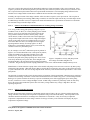
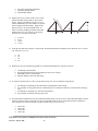
See Figure 5 in the Guide. On June 21, at 2:30 p.m., the sun is at an azimuth of about 90° W of S and an altitude
of about 60°. For the array to point at the sun, it must face at the azimuth direction and must be tilted so the
perpendicular to the array points toward the sun. This means that the tilt must be 30°. Make a sketch to prove this
to yourself.
59. c.
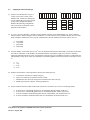
70% of 10/32 is 7/32, because 7 is 70% of 10.
60. c.
Finally, an obvious answer.
61. b.
62. a.
Incorrect polarity can severely damage the electronics in a charge controller or an inverter and, if applied to
batteries, can damage the PV cells, because the batteries will be supplying power to the PV array rather than vice
versa. The power supplied to the PV cells by the batteries will be dissipated as heat.
63. b.
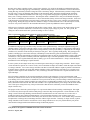
This problem involves successive applications of temperature and voltage drop factors. The temperature
coefficient for power for crystalline silicon PV modules is -0.5%/0C so the temperature losses are 0.875 (-0.5%/0C
x (500C-250C) = -12.5% or 0.875). With the combination of temperature and voltage drop the answer is V =
68.4×0.875×0.984 = 58.9 V. Note that the array maximum-power voltage is not dependent upon irradiance at
higher irradiances and is neglected in this problem.
64. c.
The correct result is obtained by multiplying 4,000 W × .90 (irradiance of 900 w/m2)× .90 (for module tolerance,
array mismatch and dust degradation) × 0.875 ((temperature derate of -.5 %/0C x (500C-250C) = -12.5% or .875)) x
.98 (wiring loss) x .94 (inverter inefficiency) = 2,612 watts, answer c.
52
The correct result is obtained from 4000 × 0.9 ×
× 0.97 × 0.95 = 2522 W.
68.4
65. c.
66. d.
The correct result is obtained from 4000×0.9×0.95×0.97×0.95 = 3152 W. (The MPT charge controller increases
the inverter output power by 630 W, or 25% from the previous example.)
67. a.
This is the anti-islanding feature of the inverter, a requirement of UL 1741 listing.
68. c.
The other answers are also good practices. The point here is that presumably there is a problem. This means that
it is possible that a switch is bad, so that even if it is in the off position, maybe it is not off. So after turning off all
relevant switches to remove power from points where wires are to be attached or removed, the voltages and
currents should be measured to be sure there are no surprises. Even then, gloves and a facemask may be
appropriate (especially on high voltage systems and battery systems) when making the connections.
Study Guide for the Applicant for NABCEP Photovoltaic Installer Certification
Version 3 – August, 2005
59