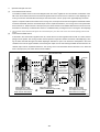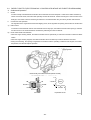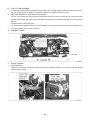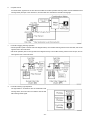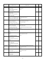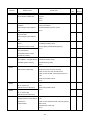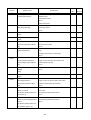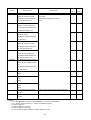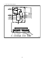
1
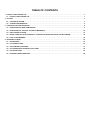
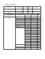
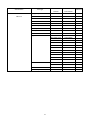
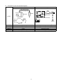
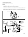
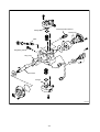
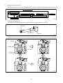
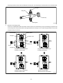
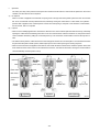
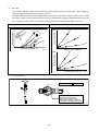
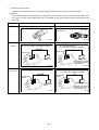
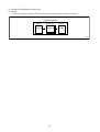
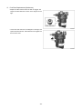
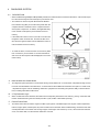
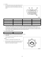
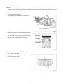
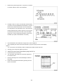
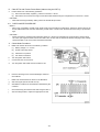
Diesel Injection Pump
SERVICE MANUAL
Common Rail System for
TOYOTA HILUX / KIJYANG INNOVA /
INNOVA 1KD/2KD
OPERATION
July, 2004
00400077
© 2004 DENSO CORPORATION
All Rights Reserved. This book may not be reproduced
or copied, in whole or in part, without the written
permission of the publisher.
TABLE OF CONTENTS
1. PRODUCT APPLICATION LIST . . . . . . . . . . . . . . . . . . . . . . . . . . . . . . . . . . . . . . . . . . . . . . . . . . . . . . . . . . . . . . . . . . . . . . . . . . . 1
1-1. PRODUCT APPLICATION LIST . . . . . . . . . . . . . . . . . . . . . . . . . . . . . . . . . . . . . . . . . . . . . . . . . . . . . . . . . . . . . . . . . . . . . . . 1
2. OUTLINE . . . . . . . . . . . . . . . . . . . . . . . . . . . . . . . . . . . . . . . . . . . . . . . . . . . . . . . . . . . . . . . . . . . . . . . . . . . . . . . . . . . . . . . . . . . . . 3
2-1. OUTLINE OF SYSTEM . . . . . . . . . . . . . . . . . . . . . . . . . . . . . . . . . . . . . . . . . . . . . . . . . . . . . . . . . . . . . . . . . . . . . . . . . . . . . . 3
2-2. SYSTEM CONFIGURATION . . . . . . . . . . . . . . . . . . . . . . . . . . . . . . . . . . . . . . . . . . . . . . . . . . . . . . . . . . . . . . . . . . . . . . . . . . 5
3. CONSTRUCTION AND OPERATION . . . . . . . . . . . . . . . . . . . . . . . . . . . . . . . . . . . . . . . . . . . . . . . . . . . . . . . . . . . . . . . . . . . . . . . 9
3-1. DESCRIPTION OF MAIN COMPONENTS . . . . . . . . . . . . . . . . . . . . . . . . . . . . . . . . . . . . . . . . . . . . . . . . . . . . . . . . . . . . . . . 9
3-2. DESCRIPTION OF CONTROL SYSTEM COMPONENTS . . . . . . . . . . . . . . . . . . . . . . . . . . . . . . . . . . . . . . . . . . . . . . . . . . 23
3-3. EGR CONTROL SYSTEM . . . . . . . . . . . . . . . . . . . . . . . . . . . . . . . . . . . . . . . . . . . . . . . . . . . . . . . . . . . . . . . . . . . . . . . . . . . 37
3-4. DIESEL THROTTLE (ELECTRONICALLY CONTROLLED INTAKE AIR THROTTLE MECHANISM) . . . . . . . . . . . . . . . . 39
3-5. FUEL FILTER WARNING . . . . . . . . . . . . . . . . . . . . . . . . . . . . . . . . . . . . . . . . . . . . . . . . . . . . . . . . . . . . . . . . . . . . . . . . . . . 40
4. DIAGNOSIS SYSTEM . . . . . . . . . . . . . . . . . . . . . . . . . . . . . . . . . . . . . . . . . . . . . . . . . . . . . . . . . . . . . . . . . . . . . . . . . . . . . . . . . . 43
4-1. DESCRIPTION . . . . . . . . . . . . . . . . . . . . . . . . . . . . . . . . . . . . . . . . . . . . . . . . . . . . . . . . . . . . . . . . . . . . . . . . . . . . . . . . . . . . 43
4-2. DTC CHECK/CLEAR . . . . . . . . . . . . . . . . . . . . . . . . . . . . . . . . . . . . . . . . . . . . . . . . . . . . . . . . . . . . . . . . . . . . . . . . . . . . . . . 45
4-3. CHECK MODE PROCEDURE . . . . . . . . . . . . . . . . . . . . . . . . . . . . . . . . . . . . . . . . . . . . . . . . . . . . . . . . . . . . . . . . . . . . . . . . 47
4-4. DTC (DIAGNOSTIC TROUBLE CODE) CHART . . . . . . . . . . . . . . . . . . . . . . . . . . . . . . . . . . . . . . . . . . . . . . . . . . . . . . . . . 48
4-5. FAIL-SAFE CHART . . . . . . . . . . . . . . . . . . . . . . . . . . . . . . . . . . . . . . . . . . . . . . . . . . . . . . . . . . . . . . . . . . . . . . . . . . . . . . . . 54
4-6. EXTERNAL WIRING DIAGRAM . . . . . . . . . . . . . . . . . . . . . . . . . . . . . . . . . . . . . . . . . . . . . . . . . . . . . . . . . . . . . . . . . . . . . . 58
1.
PRODUCT APPLICATION LIST
1-1. PRODUCT APPLICATION LIST
Exhaust
Vehicle Name
Vehicle Model
Engine Model
Reference
HILUX/KIJYANG INNOVA/INNOVA
KUN15R, KUN16R
1KD-FTV
3.0L
IMV; Since August, 2004
HILUX/KIJYANG INNOVA/INNOVA
KUN10R, KUN25R,
2KD-FTV
2.5L
IMV; Since August, 2004
2KD-FTV
KUN26R, KUN40R
Volume
1KD-FTV
DENSO Part
Car Manufacturer
Number
Part Number
Supply pump
SM294000-0350
221000L020
Injector
SM095000-5442
236700L020
Rail
SM095440-0551
238100L010
NE sensor
029600-1151
90919-05050
TDC sensor
029600-0630
90919-05025
Coolant temperature sensor
179700-0451
89422-33030
Fuel temperature sensor
179730-0020
89454-60010-B
Turbo pressure sensor
079800-7470
89421-71020
Air flow meter
VN197400-4000
-
Engine ECU
MA175800-6590
896610K200
MA175800-6600
896610K210
MA175800-6610
896610K220
MA175800-6650
896610K250
MA175800-6640
896610K260
MA175800-6630
896610K290
MA175800-6620
896610K300
MA175800-6660
896610K310
MA175800-6670
896610K320
MA175800-6680
896610K330
MA175800-6710
896610K340
MA175800-6720
896610K350
MA175800-6690
896610K360
MA175800-6670
896610K370
101310-5441
8987071011
101310-5481
8987071021
VN101397-1000
258000L010
198800-3140
7812009010
Vehicle Name
HILUX/KIJYANG INNOVA/INNOVA
1KD-FTV
Part Type
EDU
EGR valve
Accelerator pedal module
-1-
Reference
HP3
DENSO Part
Car Manufacturer
Number
Part Number
Supply pump
SM294000-0350
221000L020
Injector
SM095000-5520
236700L010
Rail
SM095440-0551
238100L010
NE sensor
029600-1151
90919-05050
TDC sensor
029600-0630
90919-05025
Coolant temperature sensor
179700-0451
89422-33030
Fuel temperature sensor
179730-0020
89454-60010-B
Turbo pressure sensor
079800-7470
89421-71020
Air flow meter
VN197400-4000
-
Engine ECU
MA175800-6800
896610K390
MA175800-6740
896610K400
MA175800-6760
896610K410
MA175800-6780
896610K440
MA175800-6790
896610K450
MA175800-6730
896610K460
MA175800-6750
896610K470
MA175800-6770
896610K480
MA175800-6830
896610K490
MA175800-6850
896610K500
MA175800-6870
896610K530
101310-5441
8987071011
101310-5481
8987071021
VN101397-0990
258000L020
198800-3140
7812009010
Vehicle Name
HILUX/KIJYANG INNOVA/INNOVA
2KD-FTV
Part Type
EDU
EGR valve
Accelerator pedal module
-2-
Reference
HP3
2.
OUTLINE
2-1. OUTLINE OF SYSTEM
•
The common rail system was developed primarily to cope with exhaust gas regulations for diesel engines, and aimed for
1. further improved fuel economy; 2. noise reduction; and 3. high power output.
•
This Common Rail System meets the Step III Stage of the
European Emission Regulations as shown in the figure on
the right.
A. System Characteristics:
The common rail system uses a type of accumulation chamber called a rail to store pressurized fuel, and injectors that
contain electronically controlled solenoid valves to spray the pressurized fuel into the cylinders. Because the engine ECU
controls the injection system (including the injection pressure, injection rate, and injection timing), the system is unaffected by the engine speed or load. This ensures a stable injection pressure at all times, particularly in the low engine speed
range, and dramatically decreases the amount of black smoke ordinarily emitted by a diesel engine during start-up and
acceleration. As a result, exhaust gas emissions are cleaner and reduced, and higher power output is achieved.
a.
Injection Pressure Control
• Enables high-pressure injection, even in the low engine speed range.
• Optimizes control to minimize particulate matter and NOx emissions.
b.
Injection Timing Control
Optimally controls the timing to suit driving conditions.
Injection Rate Control
Pilot injection control sprays a small amount of fuel before the main injection.
Common Rail System
Optimization
Common rail system
Speed
Injection timing
NOx
Conventional
pump
Particulate
Common rail system
Injection
pressure
Pilot injection
Main
injection
Crankshaft angle
Injection Quantity Control
Conventional
pump
Speed
Cylinder injection
volume correction
Speed
Optimization, High pressurization
Injection Rate Control
Injection rate
Injection Timing Control
Injection Pressure Control
Injection pressure
c.
㧝 㧟 㧠 㧞
QD0734E
-3-
B. Comparison to the Conventional System
Common Rail System
In-line, VE Pump
High-pressure Pipe
Rail
Momentary High Pressure
Timer
TWV
Nozzle
Supply Pump
Usually High Pressure
Delivery Valve
Governor
System
In-line Pump
Feed Pump SCV (Suction Control Valve)
Injector
Fuel Tank
VE Pump
Injection Quantity Control
Pump (Governor)
Engine ECU, Injector (TWV)*1
Injection Timing Control
Rising Pressure
Distributor
Pump (Timer)
Engine ECU, Injector (TWV)*1
Engine ECU, Supply Pump
Injection Pressure Control
Pump
Pump
Dependent upon Speed and Injection Quantity
Engine ECU, Rail
Engine ECU, Supply Pump (SCV)*2
*1 TWV: Two Way Valve *2 SCVSuction Control Valve
-4-
QD2341E
2-2. SYSTEM CONFIGURATION
A. Main System Components
a.
Location (1)
-5-
b.
Location (2)
-6-
B. Outline of Composition and Operation
a.
Composition
The common rail system consists primarily of a supply pump, rail, injectors, and engine ECU.
Fuel Temperature Sensor
Engine Speed
Accelerator Opening
Intake Air Pressure,
Atmospheric Air Pressure
Intake Air Temperature
Coolant Temperature
Crankshaft Angle
EDU
Engine ECU
Cylinder Recognition Sensor
Intake Airflow Rate
Pressure
Limiter
Rail
Injector
Rail Pressure
Sensor
Check Valve
Fuel
Cooler
Fuel Filter
Fuel Temperature Sensor
Supply Pump
SCV
(Suction
Control Valve) Fuel Tank
Q000705E
b.
(1)
Operation
Supply pump (HP3)
The supply pump draws fuel from the fuel tank, and pumps the high pressure fuel to the rail. The quantity of fuel discharged from the supply pump controls the pressure in the rail. The SCV (Suction Control Valve) in the supply pump
effects this control in accordance with the command received from the ECU.
(2)
Rail
The rail is mounted between the supply pump and the injector, and stores the high-pressure fuel.
(3)
Injector (X2 revised type)
This injector replaces the conventional injection nozzle, and achieves optimal injection by effecting control in accordance
with signals from the ECU. Signals from the ECU determine the length of time and the timing in which current is applied
to the injector. This in turn, determines the quantity, rate and timing of the fuel that is injected from the injector.
(4)
Engine ECU
The engine ECU calculates data received from the sensors to comprehensively control the injection quantity, timing and
pressure, as well as the EGR (exhaust gas recirculation).
-7-
C. Fuel System and Control System
a.
Fuel System
This system comprises the route through which diesel fuel flows from the fuel tank to the supply pump, via the rail, and
is injected through the injector, as well as the route through which the fuel returns to the tank via the overflow pipe.
b.
Control System
In this system, the engine ECU controls the fuel injection system in accordance with the signals received from various
sensors. The components of this system can be broadly divided into the following three types: (1) Sensors; (2) ECU; and
(3) Actuators.
(1)
Sensors
Detect the engine and driving conditions, and convert them into electrical signals.
(2)
Engine ECU
Performs calculations based on the electrical signals received from the sensors, and sends them to the actuators in order
to achieve optimal conditions.
(3)
Actuators
Operate in accordance with electrical signals received from the ECU. Injection system control is undertaken by electronically controlling the actuators. The injection quantity and timing are determined by controlling the length of time and the
timing in which the current is applied to the TWV (Two-Way Valve) in the injector. The injection pressure is determined
by controlling the SCV (Suction Control Valve) in the supply pump.
Sensor
Actuator
Engine Speed
Crankshaft Position Sensor NE
Injector
•Injection Quantity Control
•Injection Timing Control
•Injection Pressure Control
Cylinder Recognition
Cylider Recognition Sensor G
Engine
ECU
Accelerator Position Sensor
Load
Supply Pump (SCV)
•Fuel Pressure Control
Other Sensors and Switches
EGR, Air Intake Control Relay, Light
QD2380E
-8-
3.
CONSTRUCTION AND OPERATION
3-1. DESCRIPTION OF MAIN COMPONENTS
A. Supply Pump (HP3)
a.
Outline
• The supply pump consists primarily of the pump body (eccentric cam, ring cam, and plungers), SCV (Suction Control
Valve), fuel temperature sensor, and feed pump.
• The two plungers are positioned vertically on the outer ring cam for compactness.
• The engine drives the supply pump at a ratio of 1:2. The supply pump has a built-in feed pump (trochoid type), and draws
the fuel from the fuel tank, sending it to the plunger chamber.
• The internal camshaft drives the two plungers, and they pressurize the fuel sent to the plunger chamber and send it to
the rail. The quantity of fuel supplied to the rail is controlled by the SCV, using signals from the engine ECU. The SCV is
a normally closed type (the intake valve closes during de-energization).
Overflow to Fuel Tank
to Rail
Fuel Temperature Sensor
from Fuel Tank
SCV
Q000706E
Injector
Discharge Valve
Rail
Intake Valve
Plunger
Intake pressure
Feed pressure
High pressure
Return pressure
Return Spring
Return
SCV
Fuel Overflow
Regulating Valve
Fuel
Cooler
Feed Pump
Filter
Fuel Inlet
Camshaft
Intake
Fuel Filter (with Priming Pump)
Fuel Tank
Q000707E
-9-
Fuel Temperature Sensor
Plunger
Feed Pump
Filter
Regulating Valve
IN
Ring Cam
SCV
Pump Body
Drive Shaft
Plunger
Q000708E
-10-
b.
Supply Pump Internal Fuel Flow
The fuel that is drawn from the fuel tank passes through the route in the supply pump as illustrated, and is fed into the rail.
Supply pump interior
Regulating valve
Feed pump
Overflow
SCV (Suction Control Valve)
Discharge valve
Rail
Pumping portion (plunger)
Intake valve
Fuel tank
QD0705E
c.
Construction of Supply Pump
The eccentric cam is attached to the drive shaft. The eccentric cam is connected to the ring cam.
Cam Shaft
Eccentric Cam
Ring Cam
QD0706E
• As the drive shaft rotates, the eccentric cam rotates eccentrically, and the ring cam moves up and down while rotating.
Plunger
Eccentric Cam
Ring Cam
Cam Shaft
QD0727E
-11-
• The plunger and the suction valve are attached to the ring cam. The feed pump is connected to the rear of the drive shaft.
Plunger A
Ring Cam
Feed Pump
Plunger B
d.
QD0728E
Operation of the Supply Pump
As shown in the illustration below, the rotation of the eccentric cam causes the ring cam to push Plunger A upwards. Due
to the spring force, Plunger B is pulled in the opposite direction to Plunger A. As a result, Plunger B draws in fuel, while
Plunger A pumps it to the rail.
Suction Valve
Plunger A
Delivery Valve
Eccentric Cam
Ring Cam
SCV
Plunger B
Plunger A: Finish Compression
Plunger B: Finish Intake
Plunger A: Begin IntakePlunger
B: Begin Compression
Plunger A: Begin Compression
Plunger B: Begin Intake
Plunger A: Finish Intake
Plunger B: Finish Compression
QD0707E
-12-
B. Description of Supply Pump Components
a.
Feed Pump
The trochoid type feed pump, which is integrated in the supply pump, draws fuel from the fuel tank and feeds it to the two
plungers via the fuel filter and the SCV (Suction Control Valve). The feed pump is driven by the drive shaft. With the rotation of the inner rotor, the feed pump draws fuel from its suction port and pumps it out through the discharge port. This
is done in accordance with the space that increases and decreases with the movement of the outer and inner rotors.
Outer Rotor
To
Pump Chamber
Quantity Decrease
Quantity Decrease
(Fuel Discharge)
Inner Rotor
Intake Port
From
Fuel Tank
b.
Discharge
Port
Quantity Increase
Quantity Increase
(Fuel Intake)
QD0708E
SCV: Suction Control Valve
• A linear solenoid type valve has been adopted. The ECU controls the duty ratio (the duration in which current is applied
to the SCV), in order to control the quantity of fuel that is supplied to the high-pressure plunger.
• Because only the quantity of fuel that is required for achieving the target rail pressure is drawn in, the actuating load of
the supply pump decreases.
• When current flows to the SCV, variable electromotive force is created in accordance with the duty ratio, moving the valve
needle to the right side, and changing the opening of the fuel passage to regulate the fuel quantity.
• With the SCV ON, the valve spring contracts, completely opening the fuel passage and supplying fuel to the plungers.
(Full quantity intake and full quantity discharge)
• When the SCV is OFF, the force of the valve spring moves the valve needle to the left, closing the fuel passage (normally
closed).
• By turning the SCV ON/OFF, fuel is supplied in an amount corresponding to the actuation duty ratio, and fuel is discharged by the plungers.
-13-
A)
In case of long duty ON
Long duty ON => large valve opening => maximum intake quantity
Feed Pump
Plunger
SCV
Valve Needle
Large Opening
Valve Needle
3'
-14-
B)
In case of short duty ON
Short duty ON => small valve opening => minimum intake quantity
Feed Pump
Plunger
SCV
Valve Needle
Small Opening
Valve Needle
3'
-15-
C. Rail
a.
Outline
• Stores pressurized fuel (0 to 160 MPa) that has been delivered from the supply pump and distributes the fuel to each
cylinder injector. A rail pressure sensor and a pressure discharge valve (low-pressure valve) are adopted in the rail.
• The rail pressure sensor (Pc sensor) detects fuel pressure in the rail and sends a signal to the engine ECU, and the pressure limiter controls the excess pressure. This ensures optimum combustion and reduces combustion noise.
Rail Pressure Sensor
#1
OUT
#2
OUT
#3
OUT
IN
#4
OUT
Relief Passage
Pressure Limiter
Q000712E
b.
Pressure Limiter
The pressure limiter opens to release the pressure if an abnormally high pressure is generated.
Q000257E
• When the rail pressure reaches approximately 200 MPa
(2038 kg/cm2), it trips the pressure limiter (the valve
opens). When the pressure drops to approximately 50 MPa
(509.5 kg/cm2), the pressure limiter returns to its normal
state (the valve closes) in order to maintain the proper
Valve Open
200 MPa (2038 kg/cm2)
pressure.
Valve Close
50 MPa (509.5 kg/cm2)
Q000271E
-16-
D. Injector (X2 revised type)
a.
Outline
The injectors inject the high-pressure fuel from the rail into the combustion chambers at the optimum injection timing,
rate, and spray condition, in accordance with commands received from the ECU.
A)
Characteristics
• A compact, energy-saving solenoid-control type TWV (Two-Way Valve) injector has been adopted.
• QR codes displaying various injector characteristics and the ID codes showing these in numeric form (30 base 16 characters) are engraved on the injector head. The 1KD-FTV common rail system optimizes injection volume control using
this information. When an injector is newly installed in a vehicle, it is necessary to enter the ID codes in the engine ECU
using the DST-2.
b.
Construction
QR Codes
30 Base 16 Characters
Solenoid Valve
Control Chamber
Pressurized Fuel
(from Rail)
Command Piston
Multiple Hole Filter
Filter Orifice Dimensions: φ0.045x2025
Nozzle Spring
Pressure Pin
Leak Passage
Nozzle Needle
Seat
Pressurized Fuel
Q000713E
-17-
c.
Operation
The TWV (Two-Way Valve) solenoid valve opens and closes the outlet orifice to control both the pressure in the control
chamber, and the start and end of injection.
A)
No injection
When no current is supplied to the solenoid, the spring force is stronger than the hydraulic pressure in the control chamber. Thus, the solenoid valve is pushed downward, effectively closing the outlet orifice. For this reason, the hydraulic
pressure that is applied to the command piston causes the nozzle spring to compress. This closes the nozzle needle,
and as a result, fuel is not injected.
B)
Injection
• When current is initially applied to the solenoid, the attraction force of the solenoid pulls the solenoid valve up, effectively
opening the outlet orifice and allowing fuel to flow out of the control chamber. After the fuel flows out, the pressure in the
control chamber decreases, pulling the command piston up. This causes the nozzle needle to rise and the injection to
start.
• The fuel that flows past the outlet orifice flows to the leak pipe and below the command piston. The fuel that flows below
the piston lifts the piston needle upward, which helps improve the nozzle's opening and closing response.
• When current continues to be applied to the solenoid, the nozzle reaches its maximum lift, where the injection rate is also
at the maximum level. When current to the solenoid is turned OFF, the solenoid valve falls, causing the nozzle needle to
close immediately and the injection to stop.
Leak pipe
Solenoid
Actuation
current
Valve spring
TWV
Outlet orifice
Actuation
current
Actuation
current
Rail
Inlet orifice
Command
piston
Nozzle
needle
No injection
Control chamber
pressure
Control chamber
pressure
Control chamber
pressure
Injection rate
Injection rate
Injection rate
Injection
End of injection
Q000149E
-18-
d.
QR codes
• Conventionally, adjusting resistors were used for fuel injection quantity correction. However, QR *1 (Quick Response)
codes have been adopted to enhance correction precision.
• Using QR codes has resulted in a substantial increase in the number of fuel injection quantity correction points, and thus
the injection quantity control precision has improved. The characteristics of the engine cylinders have been further unified, contributing to improvements in combustion efficiency, reductions in exhaust gas emissions and so on.
Adjusting Resistance Correction Points (Conventional).
[2KD]
135MPa
105MPa
±1.2
54MPa
±1.0
±0.7
±0.6
160
Injection Quantity Q
Injection Quantity Q
±1.5
QR Code Correction Points (New)
32MPa
70
32
±1.0
Actuating Pulse Width TQ
Actuating Pulse Width TQ
QD1543E
135
Injection Quantity Q
[1KD]
80
32
Actuating Pulse Width TQ
Q000714E
*1: Location of QR codes
QR Codes (
9.9mm)
10EA 01EB
03EA 01EB
0300 0000
0000 BC
ID Codes
(30 base 16 characters)
Base 16 characters nothing
fuel injection quantity correction
information for market service use.
Q000715E
-19-
e.
Repair Procedure Changes
Differences in comparison with the conventional adjusting correction resistor injectors are as shown below.
< CAUTION >
• When replacing injectors with QR codes, or the engine ECU, it is necessary to record the ID codes (QR codes) in the
ECU. (If the ID codes of the installed injector are not registered correctly, engine failure such as rough idling and noise
will result.)
Conventional (Injector with Correction Resistor)
New (Injector with QR Codes)
25612 (almost infinite)
combinations
52 (25) combinations
ID Code
10EA 01EB
03EA 01EB
0300 0000
0000 BC
Q000716E
QD1532E
Replacing the
Injector
"Electrical recognition of correction resistance"
"No correction resistance,
so no electrical recognition capability"
Spare Injector
ѱ
Spare Injector
Engine ECU
* Necessary to record
the injector ID codes
in Engine ECU
Engine ECU
QD1534E
QD1536E
Replacing the
Engine ECU
"Electrical recognition of correction resistance"
"No correction resistance,
so no electrical recognition capability"
Vehicle-side
Injector
Vehicle-side
Injector
Spare Engine
ECU
QD1535E
-20-
ѱ
Spare Engine ECU
* Necessary to record
the injector ID codes
in the engine ECU
QD1537E
E. Engine ECU (Electronic Control Unit)
a.
Outline
This is the command center that controls the fuel injection system and engine operation in general.
(Outline Diagram)
Sensor
Engine ECU
Actuator
Detection
Calculation
Actuation
QD2352E
-21-
F. EDU (Electronic Driving Unit)
a.
Outline
The EDU has been adopted to support the high-speed actuation of the injectors. The high-speed actuation of the injector
solenoid valve is made possible through the use of a high-voltage generating device (DC/DC converter).
b.
EDU Operation
The high-voltage generating device converts the battery voltage into high voltage. The engine ECU sends signals to terminals B through E of the EDU in accordance with the signals from the sensors. Upon receiving these signals, the EDU
outputs signals to the injectors via terminals N through K. At this time, terminal F outputs the Ijf injection verification signal
to the ECU. The pressure discharge valve is controlled by PRD signals coming to terminal R.
COM2
Battery
High-voltage
Generating
Circuit
COM1
IJt#1
INJ#1
IJt#4
INJ#4
IJt#2
IJt#3
Control
Circuit
INJ#2
INJ#3
IJf
GND
Q000717E
-22-
3-2. DESCRIPTION OF CONTROL SYSTEM COMPONENTS
A. Engine Control System Diagram
-23-
B. Description of Sensors
a.
Crankshaft Position Sensor (NE)
An NE pulsar attached to the crankshaft timing gear outputs a signal for detecting the crankshaft angle and engine speed.
The pulsar gear contains 34 gears, with 2 gears missing (for 2 pulses), and the sensor outputs 34 pulses for 360°CA.
b.
Cylinder Recognition Sensor (G)
A cylinder recognition sensor (G pulsar) is attached to the supply pump timing gear, and outputs a cylinder recognition
signal. The sensor outputs 1 pulse for each 2 engine revolutions.
34 Pulses/360°CA
*1 Pulses/720°CA
Cylinder Recognition Sensor Rotor
* The pulsar gear used for actual control is shown
within the broken-lined circle.
QD2356E
Crankshaft Timing Gear
-24-
Circuit Diagram
Exterior View Diagram
ECU
G
G Input Circuit
NE
NE Input Circuit
G+
G-
* The engine ECU identifies the No. 1 cylinder when it detects the missing-tooth NE pulse
and the cylinder recognition pulse (G Pulse) simultaneously.
G Pulse
NE Pulse
720 °CA
#3 TDC
#1 TDC
115 °CA
0 1 2 3 4 5 6 7 8 9 1011121314151617 0 1 2 3 4 5 6 7 8 9 101112131415
30 °CA
10 °CA
90 °CA
180 °CA
360 °CA
QD2357E
-25-
c.
Accelerator Position Sensor
The accelerator position sensor is a non-contact point type sensor with a lever that rotates in unison with the accelerator
pedal. The voltage (VPA1, VPA2) of the output terminal varies in accordance with the rotational angle of the lever. As a
safety measure against problems such as an open circuit, the sensor contains two output voltage systems. (The output
voltage has an offset of 0.8V.)
VPA2
EP2
VCP2
VPA1
E P1
VCP1
Linear Output Characteristics Graph
(V)
5
Wiring Diagram
Sensor
VPA2
3.988V
Linear Output
Voltage
(DC5V Applied)
Hall Element (2)
4
VPA1
3
2
VPA1
0.047µF
EP1
1.6V
0.047µF
VcP1
3.188V
1
0.8V
-5
0
5
0.29
10
15
20
VPA2
25
0.047µF
15.9° [Stroke: 47mm]
Magnet
(Effective Operating Angle)
Fully Closed
Fully Open
Maximum Rotation Angle: 20.27°
Pedal Rotation Angle (°)
EP2
0.047µF
VcP2
Full Stroke
Q000719E
-26-
d.
Intake Air Pressure Sensor
This is a type of semi-conductor pressure sensor. It utilizes the characteristics of the electrical resistance changes that
occur when the pressure applied to a silicon crystal changes. Because a single sensor is used to measure both intake
air pressure and atmospheric pressure, a VSV is used to alternate between atmospheric and intake air pressure measurement.
[Exterior View]
VC
PIM
E2
TRIM
Intake Air
Pressure
Sensor
Intake Manifold
Pressure Characteristics
VC = 5 V
PIM (V)
Atmosphere
VSV
4.5
ECU
Atmospheric Pressure Measurement Conditions:
The VSV turns ON for 150msec to detect the atmospheric pressure
when one of the conditions "(1)" to "(3)" given below is present.
(1) Engine speed = 0rpm
(2) Starter is ON
(3) Idle is stable
Intake Air Pressure Measurement Conditions:
The VSV turns OFF to detect the intake air pressure if the atmospheric
pressure measurement conditions are absent.
1
13.3
253.3
100
1900
Absolute Pressure
kPa (abs)
mmHg (abs)
Q000720E
-27-
Coolant Temperature Sensor (THW)
• The coolant temperature sensor (Pc sensor) is attached to the engine cylinder block and detects the engine coolant temperature.
• The sensor uses a thermistor. The thermistor has a characteristic in which the resistance changes with the temperature,
and the change in resistance value is used to detect the coolant temperature changes.
• Its characteristic is that the resistance value decreases as the temperature increases.
Initial Resistance Value Characteristics
Temperature Resistance Value
(°C)
(kΩ)
Thermistor
-30
(25.4)
-20
15.04 +1.29
-1.20
-10
(9.16)
0
(5.74)
10
(3.70)
20
2.45+0.14
-0.13
30
(1.66)
40
(1.15)
50
(0.811)
60
(0.584)
70
(0.428)
80
0.318±0.008
90
(0.240)
100
(0.1836)
110
0.1417±0.0018
120
(0.1108)
ECU
5V
THW
(THA)
Thermistor
e.
E2
Q000721E
-28-
f.
Fuel Temperature Sensor (THF)
• The fuel temperature sensor is mounted on the supply pump, and detects the fuel temperature, sending a signal to the
engine ECU.
• The detection component utilizes a thermistor.
Resistance Value Characteristics
Temperature Resistance Value
(°C)
(kΩ)
Thermistor
-30
(25.4)
-20
15.0±1.5
-10
(9.16)
0
(5.74)
10
(3.70)
20
2.45±0.24
30
(1.66)
40
(1.15)
50
(0.811)
60
(0.584)
70
(0.428)
80
0.318±0.031
90
(0.240)
100
(0.1836)
110
(0.1417)
120
(0.1108)
Fuel Temperature
Sensor
Q000722E
-29-
C. Various Types of Controls
a.
Outline
This system effects fuel injection quantity and injection timing control more appropriately than the mechanical governor
and timer used in the conventional injection pump. The engine ECU performs the necessary calculations in accordance
with the sensors installed on the engine and the vehicle. It then controls the timing and duration of time in which current
is applied to the injectors, in order to realize both optimal injection and injection timing.
b.
Fuel Injection Rate Control Function
Pilot injection control injects a small amount of fuel before the main injection.
c.
Fuel Injection Quantity Control Function
The fuel injection quantity control function replaces the conventional governor function. It controls the fuel injection to an
optimal injection quantity based on the engine speed and accelerator position signals.
d.
Fuel Injection Timing Control Function
The fuel injection timing control function replaces the conventional timer function. It controls the injection to an optimal
timing based on the engine speed and the injection quantity.
e.
Fuel Injection Pressure Control Function (Rail Pressure Control Function)
The fuel injection pressure control function (rail pressure control function) controls the discharge volume of the pump by
measuring the fuel pressure at the rail pressure sensor and feeding it back to the ECU. It effects pressure feedback control so that the discharge volume matches the optimal (command) value set in accordance with the engine speed and
the injection quantity.
-30-
D. Fuel Injection Quantity Control
a.
Outline
This control determines the fuel injection quantity by adding coolant temperature, fuel temperature, intake air temperature, and intake air pressure corrections to the basic injection quantity calculated by the engine ECU, based on the engine operating conditions and driving conditions.
Injection Quantity Calculation Method
Accelerator Opening
Injection Quantity
The calculation consists of a comparison of the following two
values: 1. The basic injection quantity obtained from the governor
pattern, which is calculated from the accelerator position and
the engine speed, and 2. The injection quantity obtained by
adding various types of corrections to the maximum injection
quantity that is obtained from the engine speed.
The lesser of the two injection volumes is used as the basis
for the final injection quantity.
-31-
Injection Pressure Correction
Atmospheric Pressure Correction
Ambient Temperature Correction
Cold Operation Maximum
Injection Quantity Correction
Intake Air Pressure Correction
Engine Speed
Maximum
Injection
Quantity
Engine Speed
Engine Speed
Corrected
Final Injection
Quantity
Individual Cylinder Correction
Quantity
Basic Injection
Quantity
Intake Air Temperature Correction
Accelerator
Opening
Low Quantity
Side
Engine Speed
Injection Quantity
b.
EDU Actuation
Timing Calculation
QB0715E
c.
Basic Injection Quantity
The basic injection quantity is determined by the engine
quantity is increased when the accelerator position signal
is increased while the engine speed remains constant.
Basic Injection Quantity
speed (NE) and the accelerator opening. The injection
Accelerator Opening
Engine Speed
QB0716E
d.
Maximum Injection Quantity
The maximum injection quantity is calculated by adding the
rection, atmospheric pressure correction, ambient temperature correction, and the cold operation maximum injection
quantity correction to the basic maximum injection quantity
determined by the engine speed.
Basic Maximum Injection
Quantity
intake air pressure correction, intake air temperature cor-
Engine Speed
QB0717E
Starting Injection Quantity
When the starter switch is turned ON, the injection quantity
is calculated in accordance with the starting base injection
quantity and the starter ON time. The base injection quan-
change in accordance with the coolant temperature and
the engine speed.
Injection Quantity
tity and the inclination of the quantity increase/decrease
Base Injection
Quantity
STA ON Duration
Starting
STA/ON
Coolant Temperature
Low
High
Injection Quantity
e.
STA ON Duration
STA/ON
Starting
QB0718E
-32-
f.
Idle Speed Control (ISC) System
This system controls the idle speed by regulating the injection quantity in order to match the actual speed to the target
speed calculated by the engine ECU.
Conditions for Start of Control
Idle S/W
Accelerator Opening
Control Conditions
•Coolant Temperature
•Air Conditioner Load
•Gear Position
Target Speed
Calculation
Coolant Temperature
Air Conditioner S/W
Neutral S/W
Injection
Quantity
Correction
Injection Quantity
Determination
Vehicle Speed
Target Speed
Calculation
Comparison
Speed
Detection
QB0720E
g.
Idle Vibration Reduction Control
To reduce engine vibrations during idle, this function compares the angle speeds (times) of the cylinders and regulates
the injection quantity for the individual cylinders if there is a large difference, in order to achieve a smooth engine operation.
#1
#3
∆t1
#4
∆t4
∆t3
(Controls to make the cylinder ∆t equal)
#1
#3
#4
#2
#1
#3
#4
#2
Angle
Speed
Crankshaft Angle
Correction
Crankshaft Angle
QD2451E
-33-
E. Fuel Injection Timing Control
a.
Outline
Fuel injection timing is controlled by varying the timing in which current is applied to the injectors.
b.
(1)
Main and Pilot Injection Timing Control
Main Injection Timing
The engine ECU calculates the basic injection timing based on the engine speed and the final injection quantity, and
adds various types of corrections in order to determine the optimal main injection timing.
(2)
Pilot Injection Timing (Pilot Interval)
Pilot injection timing is controlled by adding a pilot interval to the main injection timing. The pilot interval is calculated
based on the final injection quantity, engine speed, coolant temperature, ambient temperature, and atmospheric pressure (map correction). The pilot interval at the time the engine is started is calculated from the coolant temperature and
engine speed.
Main Injection
Top Dead Center (TDC)
Pilot Injection
Interval
QB0723E
-34-
c.
Injection Timing Calculation Method
[1] Outline of Timing Control
0
Actual TDC
1
NE Pulse
Solenoid Valve Control Pulse
Pilot Injection
Main Injection
Nozzle Needle Lift
Pilot Injection Timing
Pilot Interval
Main Injection Timing
[2] Injection Timing Calculation Method
Basic Injection
Timing
-35-
Main Injection
Timing
Voltage Correction
Intake Air Pressure Correction
Intake Air Temperature Correction
Corrections
Coolant Temperature Correction
Injection Quantity
Atmospheric Pressure Correction
Engine Speed
QB0724E
F. Fuel Injection Rate Control
a.
Outline
While the injection rate increases with the adoption of high-pressure fuel injection, the ignition lag, which is the delay from
the time fuel is injected to the beginning of combustion, cannot be shortened to less than a certain value. As a result, the
quantity of fuel that is injected until main ignition occurs increases, resulting in an explosive combustion at the time of
main ignition. This increases both NOx and noise. For this reason, pilot injection is provided to minimize the initial ignition
rate, prevent the explosive first-stage combustion, and reduce noise and NOx.
Pilot Injection
Normal Injection
Injection Rate
Large First-stage
Combustion
(NOx and Noise)
Small First-stage
Combustion
Heat Release
Rate
-20
TDC
20
-20
40
Crankshaft Angle (deg)
TDC
20
40
Crankshaft Angle (deg)
QD2362E
G. Fuel Injection Pressure Control
a.
Fuel Injection Pressure
The engine ECU determines the fuel injection pressure
based on the final injection quantity and the engine speed.
The fuel injection pressure at the time the engine is started
Final Injection Quantity
is calculated from the coolant temperature and engine
speed.
Rail
Pressure
Engine Speed
-36-
QB0727E
3-3. EGR CONTROL SYSTEM
A. Outline and Operation
a.
Outline
By sensing the engine driving conditions and actual amount of EGR valve opening, the engine ECU electrically operates
the E-VRV, which controls the magnitude of vacuum introduced into diaphragm of EGR valve and throttle opening position with stepping motor and the amount of recirculating exhaust gas is regulated.
-37-
b.
Operation Principle of E-VRV
(1)
To increase the EGR volume:
In the stable condition shown in the center diagram,when the current* applied to the coil increases, the attraction force
FM of the coil increases. When this force becomes greater than the vacuum force FV that acts on the diaphragm, the
moving core moves downward. Because the port that connects the vacuum pump to the upper diaphragm chamber
opens in conjunction with the movement of the moving core, the output vacuum becomes higher and the EGR volume
increases. Meanwhile, because "increased output vacuum equals increased FV", the moving core moves upward with
the increase in FV. When FM and FV are equal, the port closes and the forces stabilize. Because the vacuum circuit of
the EGR is a closed loop, it maintains the vacuum in a stabilized state, providing there are no changes in the amperage.
*1: The engine ECU outputs sawtooth wave signals with a constant frequency. The value of the current is the effective (average) value of these
signals.
To decrease the EGR volume:
A decrease in the current that is applied to the coil, causes the FV to become greater than the FM. As a result, the diaphragm moves upward. The moving core also moves upward in conjunction with the movement of the diaphragm, causing the valve that seals the upper and lower diaphragm chambers to open. This causes the atmosphere in the lower
chamber to flow into the upper chamber, thus lowering the output vacuum and reducing the EGR volume. Because "decreased output vacuum equals decreased FV", the moving core moves downward with the decrease in FV. When FM
and FV are equal, the port closes and the forces stabilize.
from Vacuum Pump
to EGR Valve
Vacuum
FV
Current
Decrease
Atmosphere
(2)
FV
Diaphragm
Valve
FM
Current
Increase
FV
FM
Spring
Moving Core
FM
Coil
to Stabilized
State
to Stabilized
State
Stator Core
When applied current
decreases, (FV > FM),
and output vacuum is low.
EGR Volume: Decreased
Atmosphere
(Vacuum Force FV =
Solenoid Attraction Force FM)
Stable
When applied current
increases, (FV < FM),
and output vacuum is high.
EGR Volume: Increased
QB0787E
-38-
3-4. DIESEL THROTTLE (ELECTRONICALLY CONTROLLED INTAKE AIR THROTTLE MECHANISM)
A. Outline and Operation
a.
Outline
An electronically controlled intake air throttle valve mechanism has been adopted. Located in the intake manifold upstream of the EGR valve, this mechanism optimally controls the intake air throttle valve angle to control the flow of the
EGR gas, and reduce noise and exhaust gas emissions. The diesel throttle Assy is made by another manufacturer.
b.
Construction and Operation
The signals from the engine ECU actuate the stepping motor, which regulates the opening of the intake air throttle valve.
A)
EGR Control
To further increase the EGR volume when the EGR valve is fully open, the intake air throttle valve opening is reduced
and the vacuum in the intake manifold is increased by restricting the flow of intake air.
B)
Noise and Exhaust Gas Reduction
• When the engine is being started, the intake air throttle valve is opened fully to reduce the emission of white and black
smoke.
• When the engine is being stopped, the intake air throttle valve is closed fully to reduce vibrations and noise.
• During normal driving, the opening is regulated in accordance with the operating conditions of the engine, the coolant
temperature, and the atmospheric pressure.
Stepping Motor
Electronically Controlled Restrictor (Diesel Throttle)
A
ACOM
A
B
BCOM
ACOM
A
B
Rotor
A
B
BCOM
B
Equivalent Circuit
Connector
QD2363E
-39-
3-5. FUEL FILTER WARNING
•
A fuel filter warning light has been added to notify the driver when fuel filter clogging is detected. Although it does not
form part of the common rail system, it is included for reference as a related fuel system function.
A. Role of the Fuel Filter in the Common Rail System
The role of the fuel filter is to remove foreign material and moisture from the fuel. In particular, the common rail system
requires constantly high fuel quality as demonstrated in the following point, and the filter thus plays an extremely important role.
• Fuel lubricates the entire supply pump.
• The extremely high discharge pressure (maximum 160MPa) of the supply pump means that foreign material adhesion
may result in sliding part and valve malfunction.
B. Installation Position
C. System Operation
a.
General Description
When the fuel filter clogs, the detection switch installed on the fuel filter operates to turn ON the fuel filter warning light
on the instrument cluster.
-40-
b.
Complete Circuit
As shown below, signals from the two sensors installed on the filter (fuel filter warning switch and fuel sedimenter level
warning switch) are input to the meter ECU, and the meter ECU actuates the fuel filter warning light.
c.
Fuel Filter Clogging Warning Operation
• Normal operation (refer to the left side of the diagram below): The fuel filter warning switch contact is closed, and an ON
signal is sent to the meter ECU.
• Abnormal operation (refer to the right side of the diagram below): The fuel filter warning switch contact is open, and an
OFF signal is sent to the meter ECU.
d.
Fuel Filter Warning Light Operation
The light blinks in accordance with the sedimenter level
warning switch, and turns ON in accordance with the fuel
filter warning switch signal.
-41-
D. Fuel Filter Replacement (Reference)
• Replace the filter element when the filter is clogged. The
shape of the filter element is shown in the diagram on the
right.
• Loosen the case as shown in the diagram on the right, and
replace the filter element. Filter elements are supplied via
the TOYOTA route.
-42-
4
DIAGNOSIS SYSTEM
4-1. DESCRIPTION
• When troubleshooting Multiplex OBD (M-OBD) vehicles, the vehicle must be connected to the DST-2. Various data output
from the vehicle's Engine Control Unit (ECU) can then be read.
• The vehicle's on-board computer illuminates the Malfunction Indicator Lamp (MIL) on the instrument panel when the
computer detects a malfunction in the computer itself or in
drive system components. In addition, the applicable Diagnostic Trouble Codes (DTCs) are recorded in the ECU
memory.
• If the malfunction does not reoccur, the MIL turns ON until
the ignition switch is turned OFF, and then the MIL turns
OFF when the ignition switch is turned ON but the DTCs remain recorded in the ECU memory.
• To check the DTCs, connect the DST-2 to the DLC3 (Data
Link Connector 3) on the vehicle or connect terminals TC
and CG on the DLC3 (DTCs will be displayed in the combination meter).
A. Normal Mode and Check Mode
a.
The diagnosis system operates in "normal mode" during normal vehicle use. In normal mode, 2 trip detection logic is used
to ensure accurate detection of malfunctions. A "check mode" is also available to technicians as an option. In check mode,
1 trip detection logic is used for simulating malfunction symptoms and increasing the system's ability to detect malfunctions, including intermittent malfunctions.
B. 2 Trip Detection Logic
a.
When a malfunction is first detected, the malfunction is temporarily stored in the ECU memory (1st trip). If the same malfunction is detected during the next subsequent drive cycle, the MIL is illuminated (2nd trip).
C. Freeze Frame Data
a.
The freeze frame data records the engine conditions (fuel system, calculated engine load, engine coolant temperature,
fuel trim, engine speed, vehicle speed, etc) when a malfunction is detected. When troubleshooting, the freeze frame data
can help determine if the vehicle was running stopped, if the engine was warmed up or not, if the air-fuel ratio was lean
or rich, and other data, from the time the malfunction occurred.
-43-
D. DLC3
a.
The vehicle's ECU uses the ISO 14230 (M-OBD) communication protocol. The terminal arrangement of the DLC3
complies with ISO 15031-03 and matches the ISO 14230
format.
Symbols (Terminal No.)
Terminal Description
Condition
Specified Condition
SIL (7) - SG (5)
Bus "+" line
During transmission
Pulse generation
CG (4) - Body ground
Chassis ground
Always
Below 1Ω
SG (5) - Body ground
Signal ground
Always
Below 1Ω
BAT (16) - Body ground
Battery positive
Always
9 to 14 V
< NOTE >
• Connect the cable of the DST-2 to the DLC3, turn the ignition switch ON and attempt to use the DST-2. If the display
informs that a communication error has occurred, there is a problem either with the vehicle or with the tester.
• If communication is normal when the tester is connected to another vehicle, inspect the DLC3 on the original vehicle.
• If communication is still impossible when the tester is connected to another vehicle, the problem is probably in the tester
itself. Consult the Service Department listed in the tester's instruction manual.
E. Inspect Battery Voltage
Battery voltage
a.
11 to 14 V
If the voltage is below 11 V, recharge the battery before proceeding.
F. Check MIL
a.
The MIL illuminates when the ignition switch is turned ON
and the engine is not running.
< NOTE >
• If the MIL is not illuminated, check the MIL circuit.
b.
When the engine is started, the MIL should turn OFF. If the
lamp remains ON, the diagnosis system has detected a
malfunction or abnormality in the system.
-44-
4-2. DTC CHECK/CLEAR
< CAUTION >
• DST-2 only: When the diagnosis system is changed from normal mode to check mode, or vice versa, all the DTCs and
freeze frame data recorded in normal mode are erased. Before changing modes, always check and make a note of any
DTCs and freeze frame data.
A. Check DTC (using the DST-2)
a.
Connect the DST-2 to the DLC3.
b.
Turn the ignition switch ON and turn the DST-2 ON.
c.
Enter the following menus: Powertrain/Engine and ECT/
DTC.
d.
Check and make a note of DTCs and freeze frame data.
e.
See page 48 to confirm the details of the DTCs.
B. Check DTC (not using the DST-2)
a.
Turn the ignition switch ON.
b.
Using SST (09843-18040), connect between terminals 13
(TC) and 4 (CG) of the DLC3.
-45-
c.
Read DTCs by observing the MIL. If any DTC is not detected, the MIL blinks as shown in the illustration.
d.
Example: If DTCs 12 and 31 are detected, the MIL flashes
once (for 0.5 second) and flashes twice after the 1.5 second
interval, then, flashes 3 times after a 2.5 second interval
from the previous DTC and flashes once. If the interval between the previous DTC and the next DTC is 4.5 seconds,
it means the previous DTC is the last one of the multiple
string DTCs. The MIL repeats the indication of DTCs from
the initial cycle (refer to the illustration on the left).
e.
Check the details of the malfunction using the DTC chart on page 48.
f.
After completing the check, disconnect terminals 13 (TC) and 4 (CG) and turn off the display.
< NOTE >
• If 2 or more DTCs are detected, the MIL will indicate the smaller number DTC first.
g.
See page 48 to confirm the details of the DTCs.
C. Clear DTCs and Freeze Frame Data (using the DST-2)
a.
b.
Connect the DST-2 to the DLC3.
Turn the ignition switch ON (do not start the engine) and
turn the DST-2 ON.
c.
Enter the following menus: Powertrain/Engine and ECT/
DTC/Clear.
d.
Erase DTCs and freeze frame data by pressing the YES
button on the tester.
-46-
D. Clear DTCs and Freeze Frame Data (without using the DST-2)
a.
Perform either one of the following operations.
(1)
Disconnect the battery negative (-) cable for more than 1 minute.
(2)
Remove the EFI fuse from the engine room R/B located inside the engine compartment for more than 1 minute.
< CAUTION >
• When disconnecting the battery cable, perform the INITIALIZE procedure.
4-3. CHECK MODE PROCEDURE
< NOTE >
• DST-2 only: Compared to normal mode, check mode is more sensitive to malfunctions. Therefore, check mode can detect the malfunctions that cannot be detected by normal mode. In check mode, the ECU sets DTCs using 1 trip detection
logic.
< CAUTION >
• All the stored DTCs and freeze frame data are erased if: 1) the ECU is changed from normal mode to check mode or
vice versa; 2) the ignition switch is turned from ON to ACC or OFF while in check mode. Before changing modes, always
check and make a note of any DTCs and freeze frame data.
A. Check Mode Procedure
a.
Make sure that the vehicle is in the following condition:
(1)
Battery voltage 11 V or more.
(2)
Throttle valve fully closed.
(3)
Shift lever in N position.
(4)
A/C switch turned OFF.
b.
Turn the ignition switch OFF.
c.
Connect the DST-2 to the DLC3.
d.
Turn the ignition switch ON and turn the DST-2 ON.
e.
Enter the following menus: Powertrain/Engine and ECT/
Check Mode.
f.
Make sure the MIL flashes as shown in the illustration.
g.
Start the engine (the MIL should turn off).
h.
Simulate the conditions of the malfunction described by the
customer.
i.
Check the DTC(s) and freeze frame data using the DST-2.
j.
After checking the DTC, inspect the appropriate circuits.
-47-
4-4. DTC (DIAGNOSTIC TROUBLE CODE) CHART
< NOTE >
• The parameters listed in the chart are for reference only. Factors such as instrument type may cause readings to differ
slightly from stated values.
• If any DTCs are displayed during a check mode DTC check, check the circuit for the DTCs listed in the table below.
DTC No.
P0045*3
Detection Item
*1
*2
MIL
Memory
Ο
Ο
Ο
Ο
Ο
Ο
Ο
Ο
Ο
Ο
Ο
Ο
Ο
Ο
Trouble Area
Turbo/Super Charger Boost
- Turbo motor driver
Control Solenoid Circuit/Open
- Open or short in turbo motor driver circuit
[Turbocharger system malfunc-
- ECU
tion]
P0087/49
Fuel Rail/System Pressure - Too
- Open or short in fuel pressure sensor circuit
Low
- Fuel pressure sensor
[Fuel pressure sensor system
- ECU
malfunction]
P0088/78
Fuel Rail/System Pressure - Too
- Supply pump (suction control valve)
High
- Pressure limiter
[Common rail system malfunc-
- Short in supply pump (suction control valve) cir-
tion]
cuit
- ECU
P0093/78
Fuel System Leak Detected -
- Fuel line between supply pump and common rail
Large Leak
- Fuel line between common rail and each injector
[Fuel leaks in common rail sys-
- Supply pump
tem]
- Common rail
- Injectors
- Pressure limiter
- Open or short in EDU circuit (P0200 set simultaneously)
- Open or short in injector circuit
- EDU (P0200 set simultaneously)
- ECU
P0095/23*3,*4 Intake Air Temperature Sensor 2
Circuit
[Intake air temperature sensor
- Open or short in diesel turbo IAT sensor circuit
- Diesel turbo IAT sensor
- ECU
(intake air connector)]
P0097/23*3,*4 Intake Air Temperature Sensor 2
Circuit Low
[Intake air temperature sensor
low input (intake air connector)]
P0098/23*3,*4 Intake Air Temperature Sensor 2
Circuit High
[Intake air temperature sensor
high input (intake air connector)]
-48-
DTC No.
P0100/31*3
Detection Item
*1
*2
MIL
Memory
Ο
Ο
Ο
Ο
Ο
Ο
Ο
Ο
Ο
Ο
Ο
Ο
Ο
Ο
Ο
Ο
Ο
Ο
Ο
Ο
Trouble Area
Mass or Volume Air Flow Circuit
- Open or short in MAF meter circuit
[Mass air flow meter]
- MAF meter
- ECU
P0102/31*3
P0103/31*3
Mass or Volume Air Flow Meter
- Open or short in MAF meter circuit
Circuit Low Input
- MAF meter
[Mass air flow meter low input]
- ECU
Mass or Volume Air Flow Meter
Circuit High Input
[Mass air flow meter high input]
P0105/31
Manifold Absolute Pressure/
Barometric Pressure Circuit
[Intake air pressure sensor]
- Open or short in manifold absolute pressure sensor circuit
- Manifold absolute pressure sensor
- Turbocharger sub-assy
- EGR valve assy
- ECU
P0107/31
Manifold Absolute Pressure/
Barometric Pressure Circuit Low
P0108/31
- Open or short in manifold absolute pressure sensor circuit
Input
- Manifold absolute pressure sensor
[Intake air pressure sensor low
- Turbocharger sub-assy
input]
- EGR valve assy
Manifold Absolute Pressure/
- ECU
Barometric Pressure Circuit High
Input
[Intake air pressure sensor high
input]
P0110/24
P0112/24
Intake Air Temperature Circuit
- Open or short in IAT sensor circuit
[Intake air temperature sensor
- IAT sensor (built into MAF meter)
(built into mass air flow meter)]
- IAT sensor*4,*5
Intake Air Temperature Circuit
- ECU
*1
Low Input
[Intake air temperature sensor
(built into mass air flow meter)
low input]
P0113/24
Intake Air Temperature Circuit
High Input
[Intake air temperature sensor
(built into mass air flow meter)
high input]
P0115/22
Engine Coolant Temperature Cir- - Open or short in ECT sensor circuit
cuit
- ECT sensor
[Engine coolant temperature
- ECU
sensor]
-49-
*1
*2
MIL
Memory
Ο
Ο
Ο
Ο
Ο
Ο
Ο
Ο
Ο
Ο
- Fuel temperature sensor
Ο
Ο
Fuel Temperature Sensor "A"
- Open or short in fuel temperature sensor circuit
Ο
Ο
Circuit
- Fuel temperature sensor
[Fuel temperature sensor]
- ECU
Ο
Ο
Ο
Ο
Ο
Ο
Ο
Ο
Ο
Ο
DTC No.
P0117/22
Detection Item
Trouble Area
Engine Coolant Temperature Cir- - Open or short in ECT sensor circuit
cuit Low Input
- ECT sensor
[Engine coolant temperature
- ECU
sensor low input]
P0118/22
Engine Coolant Temperature Circuit High Input
[Engine coolant temperature
sensor high input]
P0120/41
P0122/41
P0123/41
Throttle/Pedal Position Sensor/
- Open or short in throttle position sensor circuit
Switch "A" Circuit[Intake shutter
- Throttle position sensor
(throttle valve) position sensor]
- ECU
Throttle/Pedal Position Sensor/
- Throttle position sensor
Switch "A" Circuit Low
- Open or short in VLU circuit
Input[Intake shutter (throttle
- Open in VC circuit
valve) position sensor low input]
- ECU
Throttle/Pedal Position Sensor/
- Throttle position sensor
Switch "A" Circuit High
- Open in E2 circuit
Input[Intake shutter (throttle
- VC and VTA circuits are short-circuited
valve) position sensor high input] - ECU
P0168/39
Fuel Temperature Too High
[Fuel temperature sensor rationality]
P0180/39
P0182/39
Fuel Temperature Sensor "A"
Circuit Low Input
[Fuel temperature sensor low
input]
P0183/39
Fuel Temperature Sensor "A"
Circuit High Input
[Fuel temperature sensor high
input]
P0190/49
Fuel Rail Pressure Sensor Cir-
- Open or short in fuel pressure sensor circuit
cuit[Fuel pressure sensor]
- Fuel pressure sensor
- ECU
P0192/49
P0193/49
Fuel Rail Pressure Sensor Cir-
- Open or short in fuel pressure sensor circuit
cuit Low Input
- Fuel pressure sensor
[Fuel pressure sensor low input]
- ECU
Fuel Rail Pressure Sensor Circuit High Input
[Fuel pressure sensor high input]
-50-
DTC No.
P0200/97
Detection Item
*1
*2
MIL
Memory
Ο
Ο
Ο
Ο
Ο
Ο
Ο
Ο
Trouble Area
Injector Circuit/Open[EDU sys-
- Open or short in EDU circuit
tem for injector malfunction]
- Injector
- EDU
- ECU
P0234*3
P0299*3
Turbo/Super Charger Overboost
- Turbocharger sub-assy
Condition
- Turbo motor driver
[Turbocharger system malfunc-
- Manifold absolute pressure sensor
tion]
- ECU
Turbo/Super Charger Underboost Condition
[Turbocharger system malfunction]
P0335/12
P0339/13
Crankshaft Position Sensor "A"
- Open or short in crankshaft position sensor circuit
Circuit
- Crankshaft position sensor
[Crankshaft position sensor]
- Sensor plate (crankshaft timing pulley)
Crankshaft Position Sensor "A"
- ECU
/
Ο
- Open or short in camshaft position sensor circuit
Ο
Ο
Ο
Ο
Ο
Ο
Circuit Intermittent
[Crankshaft position sensor
intermittent problem]
P0340/12
Camshaft Position Sensor "A"
Circuit (Bank 1 or Single Sensor) - Camshaft position sensor
[Camshaft position sensor]
- Camshaft timing pulley
- ECU
P0400*4,*5
Exhaust Gas Recirculation Flow
- EGR valve stuck
[EGR system malfunction]
- EGR valve does not move smoothly
- Open or short in E-VRV for EGR circuit
- Open or short in EGR valve position sensor circuit
- EGR valve position sensor
- ECU
P0405*4,*5
Exhaust Gas Recirculation Sensor "A" Circuit Low
P0406*4,*5
- Open or short in EGR valve position sensor circuit
[EGR lift sensor malfunction]
- EGR valve position sensor
Exhaust Gas Recirculation Sen-
- ECU
Ο
Ο
- Open or short in diesel throttle control motor cir-
Ο
Ο
sor "A" Circuit High
[EGR lift sensor malfunction]
P0488/15
Exhaust Gas Recirculation
Throttle Position Control Range/
cuit
Performance
- Open or short in diesel throttle valve fully opened
[Intake shutter]
switch circuit
- Diesel throttle valve assy
- ECU
-51-
*1
*2
MIL
Memory
Ο
Ο
/
Ο
/
/
Ο
Ο
Ο
Ο
Ο
Ο
Ο
Ο
Ο
Ο
- ECU
Ο
Ο
Intake Manifold Runner Control
- VSV for swirl control valve
Ο
Ο
Circuit/Open (Bank 1)
- Open or short in VSV for swirl control valve
[Swirl control system malfunc-
- Intake manifold (swirl control valve)
tion]
- ECU
Throttle/Pedal Position Sensor/
- Open or short in accelerator pedal position sen-
Ο
Ο
Ο
Ο
DTC No.
P0500/42
Detection Item
Trouble Area
Vehicle Speed Sensor "A"
- Open or short in speed sensor circuit
[Vehicle speed sensor]
- Speed sensor
- Combination meter
- ECU
- Skid control ECU
P0504/51
Brake Switch "A"/"B" Correlation
- Short in stop lamp switch signal circuit
[Stop lamp rationality]
- Stop lamp switch
- ECU
P0606
ECU/PCM Processor
- ECU
[ECU]
P0607
Control Module Performance
[ECU]
P0627
P1229/78
Fuel Pump Control Circuit/Open
- Open or shot in suction control valve circuit
[Common rail system malfunc-
- Suction control valve
tion]
- ECU
Fuel Pump System[Common rail
- Short in supply pump (suction control valve) cir-
system malfunction]
cuit
- Supply pump (suction control valve)
- ECU
P1251*3
P1601/89
Step Motor For Turbocharger
- Turbo motor driver
Control Circuit (Intermittent)
- Open or short in turbo motor driver circuit
[Turbocharger system malfunc-
- Turbocharger sub-assy
tion]
- ECU
Injector Correction Circuit (EE-
- Injector compensation code
PROM)
- ECU
[ECU]
P1611/17
IC Circuit Malfunction
[ECU]
P2008*3
P2120/19
Switch "D" Circuit
P2121/19
sor circuit
[Accelerator pedal position sen-
- Accelerator pedal position sensor
sor (sensor 1)]
- ECU
Throttle/Pedal Position Sensor/
- Accelerator pedal position sensor circuit
Switch "D" Circuit Range/Perfor-
- Accelerator pedal position sensor
mance
- ECU
[Accelerator pedal position sensor rationality (sensor 1)]
-52-
DTC No.
P2122/19
Throttle/Pedal Position Sensor/
Switch "D" Circuit Low Input
P2123/19
*1
*2
MIL
Memory
Ο
Ο
Ο
Ο
Ο
Ο
Ο
Ο
Ο
Ο
Ο
Ο
Ο
Ο
Ο
Ο
Ο
Ο
- Open or short TCM and ECU circuit- TCM- ECU
/
Ο
- Immobilizer system
/
Ο
Detection Item
Trouble Area
- Open or short in accelerator pedal position sensor circuit
[Accelerator pedal position sen-
- Accelerator pedal position sensor
sor low input (sensor 1)]
- ECU
Throttle/Pedal Position Sensor/
Switch "D" Circuit High Input
[Accelerator pedal position sensor high input (sensor 1)]
P2125/19
Throttle/Pedal Position Sensor/
Switch "E" Circuit
[Accelerator pedal position sensor (sensor 2)]
P2127/19
Throttle/Pedal Position Sensor/
Switch "E" Circuit Low Input
[Accelerator pedal position sensor low input (sensor 2)]
P2128/19
Throttle/Pedal Position Sensor/
Switch "E" Circuit High Input
[Accelerator pedal position sensor high input (sensor 2)]
P2138/19
Throttle/Pedal Position Sensor/
Switch "D"/"E" Voltage Correlation
[Accelerator pedal position sensor malfunction]
P2226/A5*6
Barometric Pressure Circuit
- ECU
[ECU]
P2228/A5*6
Barometric Pressure Circuit Low
Input
[ECU]
P2229/A5*6
Barometric Pressure Circuit High
Input
[ECU]
U0001/A2*6
High Speed CAN Communication Bus
B2799
Engine Immobilizer System Malfunction
< NOTE >
• *1: "Ο": MIL (Malfunction Indicator Lamp) illuminates, "/": MIL does not illuminate.
• *2: "Ο": DTC is stored in the ECU, "/": DTC is not stored in the ECU.
• *3: Only for 1KD-FTV.
• *4: Only for 2KD-FTV (w/ CAC).
• *5: Only for 2KD-FTV (w/o CAC).
• *6: "A" in the above table indicates that the MIL flashes 10 times.
-53-
4-5. FAIL-SAFE CHART
A. Fail-Safe Chart
If any of the following DTCs are set, the ECU enters fail-safe mode to allow the vehicle to be driven temporarily.
DTC No.
P0045
Detection Item
Fail-Safe Operation
Fail-Safe Deactivation
Conditions
Limits engine power
Ignition switch OFF
Limits engine power
Ignition switch OFF
Limits engine power
Ignition switch OFF
Fuel System Leak Detected - Large
Limits engine power for 1 minute and
Ignition switch OFF
Leak
then stalls the engine
Turbo/Super Charger Boost Control
Solenoid Circuit/Open
[Turbocharger system malfunction]
P0087/49
Fuel Rail/System Pressure - Too Low
[Fuel pressure sensor system malfunction]
P0088/78
Fuel Rail/System Pressure - Too High
[Common rail system malfunction]
P0093/78
[Fuel leaks in common rail system]
P0095/23*1,*2 Intake Air Temperature Sensor 2 Circuit
Intake air (intake manifold) tempera-
Pass condition detected
ture fixed at 145°C (293°F)
[Intake air temperature sensor (intake
air connector)]
P0097/23*1,*2 Intake Air Temperature Sensor 2 Circuit Low
[Intake air temperature sensor low
input (intake air connector)]
P0098/23*1,*2 Intake Air Temperature Sensor 2 Circuit High
[Intake air temperature sensor high
input (intake air connector)]
P0100/31*1
Mass or Volume Air Flow Circuit
Limits engine power
[Mass air flow meter]
P0102/31*1
Mass or Volume Air Flow Meter Circuit
Low Input
[Mass air flow meter low input]
P0103/31
*1
Mass or Volume Air Flow Meter Circuit
High Input
[Mass air flow meter high input]
-54-
Pass condition detected
DTC No.
Detection Item
P0105/31
Manifold Absolute Pressure/Baromet-
Fail-Safe Operation
Fail-Safe Deactivation
Conditions
Turbo pressure fixed at specified value Pass condition detected
ric Pressure Circuit
[Intake air pressure sensor]
P0107/31
Manifold Absolute Pressure/Barometric Pressure Circuit Low Input
[Intake air pressure sensor low input]
P0108/31
Manifold Absolute Pressure/Barometric Pressure Circuit High Input
[Intake air pressure sensor high input]
P0110/24
Intake Air Temperature Circuit
Intake air (mass air flow meter) tem-
[Intake air temperature sensor (built
perature value fixed
Pass condition detected
into mass air flow meter)]
P0112/24
Intake Air Temperature Circuit Low
Input
[Intake air temperature sensor (built
into mass air flow meter) low input]
P0113/24
Intake Air Temperature Circuit High
Input
[Intake air temperature sensor (built
into mass air flow meter) high input]
P0115/22
P0117/22
Engine Coolant Temperature Circuit
Fuel temperature sensor output fixed
[Engine coolant temperature sensor]
at specified value (fixed value varies
Engine Coolant Temperature Circuit
depending on conditions)
Pass condition detected
Low Input
[Engine coolant temperature sensor
low input]
P0118/22
Engine Coolant Temperature Circuit
High Input
[Engine coolant temperature sensor
high input]
P0120/41
Throttle/Pedal Position Sensor/Switch
Limits engine power
Ignition switch OFF
Limits engine power
Pass condition detected
"A" Circuit
P0122/41
Throttle/Pedal Position Sensor/Switch
"A" Circuit Low Input
P0123/41
Throttle/Pedal Position Sensor/Switch
"A" Circuit High Input
P0168/39
Fuel Temperature Too High
[Fuel temperature sensor rationality]
-55-
DTC No.
P0180/39
P0182/39
Detection Item
Fail-Safe Operation
Fuel Temperature Sensor "A" Circuit
Fuel temperature fixed at 40°C
[Fuel temperature sensor]
(104°F)
Fail-Safe Deactivation
Conditions
Pass condition detected
Fuel Temperature Sensor "A" Circuit
Low Input
[Fuel temperature sensor low input]
P0183/39
Fuel Temperature Sensor "A" Circuit
High Input
[Fuel temperature sensor high input]
P0190/49
Fuel Rail Pressure Sensor Circuit
Limits engine power
Ignition switch OFF
Limits engine power
Ignition switch OFF
Limits engine power
Ignition switch OFF
Limits engine power
Ignition switch OFF
Limits engine power
Pass condition detected
Limits engine power
Pass condition detected
Limits engine power
Ignition switch OFF
Vehicle speed fixed at 0 km/h (0 mph)
Pass condition detected
Limits engine power
Pass condition detected
Limits engine power
Ignition switch OFF
Limits engine power
Ignition switch OFF
Limits engine power
Ignition switch OFF
[Fuel pressure sensor]
P0192/49
Fuel Rail Pressure Sensor Circuit Low
Input
[Fuel pressure sensor low input]
P0193/49
Fuel Rail Pressure Sensor Circuit High
Input
[Fuel pressure sensor high input]
P0200/97
Injector Circuit/Open
[EDU system for injector malfunction]
P0234*1
Turbo/Super Charger Exessive Boost
[Turbocharger system malfunction]
P0299
*1
Turbo/Super Charger Insufficient
Boost
[Turbocharger system malfunction]
P0335/12
Crankshaft Position Sensor "A" Circuit
[Crankshaft position sensor]
P0340/12
Camshaft Position Sensor "A" Circuit
(Bank 1 or Single Sensor)
[Camshaft position sensor]
P0488/15
Exhaust Gas Recirculation Throttle
Position Control Range/Performance
[Intake shutter]
P0500/42
Vehicle Speed Sensor "A"
[Vehicle speed sensor]
P0627/78
Fuel Pump Control Circuit/Open
[Common rail system malfunction]
P1229/78
Fuel Pump System[Common rail system malfunction]
P1251*1
Turbo/Super Charger Excessive Boost
(Too High)
[Turbocharger system malfunction]
P1611/17
IC Circuit Malfunction[ECU]
-56-
DTC No.
Detection Item
P2120/19
Throttle/Pedal Position Sensor/Switch
Fail-Safe Operation
Fail-Safe Deactivation
Conditions
Limits engine power
Ignition switch OFF
Atmospheric pressure fixed
Pass condition detected
"D" Circuit
[Accelerator pedal position sensor
(sensor 1)]
P2121/19
Throttle/Pedal Position Sensor/Switch
"D" Circuit Range/Performance
[Accelerator pedal position sensor
rationality (sensor 1)]
P2122/19
Throttle/Pedal Position Sensor/Switch
"D" Circuit Low Input
[Accelerator pedal position sensor low
input (sensor 1)]
P2123/19
Throttle/Pedal Position Sensor/Switch
"D" Circuit High Input
[Accelerator pedal position sensor
high input (sensor 1)]
P2125/19
Throttle/Pedal Position Sensor/Switch
"E" Circuit
[Accelerator pedal position sensor
(sensor 2)]
P2127/19
Throttle/Pedal Position Sensor/Switch
"E" Circuit Low Input
[Accelerator pedal position sensor low
input (sensor 2)]
P2128/19
Throttle/Pedal Position Sensor/Switch
"E" Circuit High Input
[Accelerator pedal position sensor
high input (sensor 2)]
P2138/19
Throttle/Pedal Position Sensor/Switch
"D"/"E" Voltage Correlation
[Accelerator pedal position sensor
malfunction]
P2226/A5
Barometric Pressure Circuit
[ECU]
P2228/A5
Barometric Pressure Circuit Low Input
[ECU]
P2229/A5
Barometric Pressure Circuit High Input
[ECU]
< NOTE >
• *1: Only for 1KD-FTV.
• *2: Only for 2KD-FTV (w/ CAC).
• *3: Only for 2KD-FTV (w/o CAC).
-57-
4-6. EXTERNAL WIRING DIAGRAM
A. External ECU Wiring Diagram
a.
Wiring Diagram (1)
-58-
b.
Wiring Diagram (2)
-59-
c.
Wiring Diagram (3)
-60-
B. ECU Connector Diagram
a.
Connector Terminal Layout
Connector Terminal Configuration: 135 pin
34P
35P
1
E01 E02
VNTI
7
35
PCV+ PCV-
E1
VNTC
SCV
THA
THF E2
28
34
75
VCT
EGR
VG
G+
EGLS EVG
G-
31P
70
LUSL
EGRC
ALT
NE+ PCR1 INJF #1 #2 #3 #4 THIA THW VC
NE-
35P
41
PI
BATT
105
STA NSW
EOM GREM GIND
STP ST1- VCH
CAN+ CAN- HSW ACT AC1 SPD
VLU PIM
62
69
OILM
97
IMI IMO
104
130
111
TACH DM THW0 +B
W TC IREL IGSW MREL
VPA2 VPA CCS
WFSE SIL
EPA2 EPA
VCP2 VCPA
135
Q000938E
< NOTE >
• The standard normal voltage between each pair of ECU terminals is shown in the table below. The appropriate conditions
for checking each pair of terminals are also indicated.
• The result of checks should be compared with the standard normal voltage for that pair of terminals, displayed in the
Specified Condition column.
• The illustration above can be used as a reference to identify the ECU terminal locations.
Symbols (Terminal No.)
BATT (E6-2) - E1 (E8-7)
Wiring Color
L-BR
Terminal Description
Battery (for measuring
Condition
Specified Condition
Always
9 to 14 V
Ignition switch
Ignition switch ON
9 to 14 V
Power source of ECU
Ignition switch ON
9 to 14 V
MAIN Relay
Ignition switch ON
9 to 14 V
Ignition switch OFF
0 to 1.5 V
Ignition switch ON
4.5 to 5.5 V
Accelerator pedal posi-
Ignition switch ON, acceler-
0.5 to 11 V
tion sensor (for engine
ator pedal fully released
control)
Ignition switch ON, acceler-
battery voltage and for
ECU memory)
IGSW (E5-9) - E1 (E8-7)
+B (E5-1) - E1 (E8-7)
MREL (E5-8) - E1 (E8-7)
VC (E7-18) - E1 (E8-7)
B-O-BR
B-BR
W-G-BR
R-W-BR
Power source of sensor
(a specific voltage)
VPA1 (E5-22) - EP1 (E5-28)
W-L-BR-W
2.6 to 4.5 V
ator pedal fully depressed
VPA2 (E5-23) - EP2 (E5-29)
GR-G-BR-Y
Accelerator pedal posi-
Ignition switch ON, acceler-
tion sensor (for sensor
ator pedal fully released
malfunction detection)
Ignition switch ON, acceler-
1.2 to 2.0 V
3.4 to 5.0 V
ator pedal fully depressed
VCP1 (E5-26) - EP1 (E5-28)
LG-R-BR-W
Power source of acceler- Ignition switch ON
4.5 to 5.0 V
ator pedal position sensor (for VPA)
VCP2 (E5-27) - EP2 (E5-29)
BR-R-BR-Y
Power source of acceler- Ignition switch ON
4.5 to 5.0 V
ator pedal position sensor (for VPA2)
VG (E8-24) - EVG (E8-32)
W-R-B-W
MAF meter
Idling, A/C switch OFF
0.5 to 3.4 V
THA (E7-31) - E2 (E7-28)
Y-B-BR
IAT sensor
Idling, intake air tempera-
0.5 to 3.4 V
Y-G-BR
THIA (E7-20) - E2 (E7-28)
Y-G-BR
ture at 20°C (68°F)
Diesel turbo IAT sensor
Atmospheric air temperature
-61-
0.5 to 3.4 V
Symbols (Terminal No.)
THW (E7-19) - E2 (E7-28)
Wiring Color
R-L-BR
Terminal Description
ECT sensor
Condition
Specified Condition
Idling, engine coolant tem-
0.2 to 1.0 V
perature at 80°C (176°F)
STA (E5-7) - E1 (E8-7)
B-Y-BR
Starter signal
Cranking
6.0 V or more
Injector
Idling
Pulse generation
Camshaft position sen-
Idling
Pulse generation
Idling
Pulse generation
L-Y-BR
#1 (E7-24) - E1 (E8-7)
B-W-BR
#2 (E7-23) - E1 (E8-7)
R-BR
#3 (E7-22) - E1 (E8-7)
V-BR
#4 (E7-21) - E1 (E8-7)
Y-R-BR
G + (E8-23) - G - (E8-31)
Y-L
sor
NE + (E7-27) - NE - (E7-34)
Y-L
Crankshaft position sensor
STP (E6-15) - E1 (E8-7)
G-W-BR
Stop lamp switch
Ignition switch ON, brake
7.5 to 14 V
pedal depressed
Ignition switch ON, brake
0 to 1.5 V
pedal released
ST1 - (E6-14) - E1 (E8-7)
R-L-BR
Stop lamp switch
Ignition switch ON, brake
(opposite to STP)
pedal depressed
Ignition switch ON, brake
0 to 1.5 V
7.5 to 14 V
pedal released
TC (E5-11) - E1 (E8-7)
P-W-BR
Terminal TC of DLC3
Ignition switch ON
9 to 14 V
W (E5-12) - E1 (E8-7)
R-B-BR
MIL
MIL illuminated
0 to 3 V
MIL not illuminated
9 to 14 V
SP1 (E6-17) - E1 (E6-7)
SIL (E5-18) - E1 (E6-7)
V-R-BR
R-Y-BR
Speed signal from com-
Ignition switch ON, rotate
bination meter
driving wheel slowly
Terminal SIL of DLC3
Connect the DST-2 to the
Pulse generation
Pulse generation
DLC3
PIM (E8-28) - E2 (E7-28)
L-B-BR
Manifold absolute pres-
Apply negative pressure of
sure sensor
40 kPa (300 mmHg, 11.8
1.2 to 1.6 V
in.Hg)
Same as atmospheric pres-
1.3 to 1.9 V
sure
Apply positive pressure of
3.2 to 3.8 V
69 kPa (518 mmHg, 20.4
in.Hg)
IREL (E5-10) - E1 (E8-7)
B-W-BR
EDU relay
Ignition switch OFF
9 to 14 V
Idling
0 to 1.5 V
TACH (E5-4) - E1 (E8-7)
B-W-BR
Engine speed
Idling
Pulse generation
PCR1 (E7-26) - E2 (E7-28)
R-Y-BR
Common rail pressure
Idling
1.3 to 1.8 V
sensor (main)
GREL (E5-15) - E1 (E8-7)
R-BR
GLOW relay
-62-
Cranking
9 to 14 V
Idling
0 to 1.5 V
Symbols (Terminal No.)
THF (E7-29) - E2 (E7-28)
ALT (E7-8) - E1 (E6-7)
PCV + (E7-2) - PCV - (E7-1)
INJF (E7-25) - E1 (E8-7)
Wiring Color
Terminal Description
G-B-BR
Fuel temperature sensor
Ignition switch ON
G-BR
Generator duty ratio
Idling
Pulse generation
G-W-G-Y
Suction control valve
Idling
Pulse generation
EDU
Idling
Pulse generation
P-BR
Condition
Specified Condition
0.5 to 3.4 V
VNTO (E7-10) - E1 (E8-7)
B-O-BR
Turbo motor driver
Ignition switch ON
Pulse generation
VNTI (E7-17) - E1 (E8-7)
R-B-BR
Turbo motor driver
Ignition switch ON
Pulse generation
VLU (E8-29) - E2 (E7-28)
B-BR
Throttle position sensor
Ignition switch ON, intake
3.0 to 4.0 V
shutter (throttle valve) fully
opened
Ignition switch ON, intake
0.4 to 1.0 V
shutter (throttle valve) fully
closed
LUSL (E8-4) - E2 (E7-28)
EGLS (E8-33) - E2 (E7-28)
GR-BR
L-Y-BR
Diesel throttle duty sig-
Engine warmed up, racing
nal
engine
EGR valve position sen-
Ignition switch ON
sor
-63-
Pulse generation
0.6 to 1.4 V
C. EDU External Wiring Diagram
I
Battery
A
High-voltage
Generating
Circuit
H
IJt#1
IJt#4
IJt#2
B
J
C
K
Control
Circuit
D
IJt#3
L
E
IJf
COM2
M
COM1
INJ#1
INJ#4
INJ#2
INJ#3
F
G
A
I
H
J K
GND
L
M
F B C
D E G
Q000928E
-64-
Published
: July 2004
Edited and published by:
DENSO CORPORATION
Service Department
1-1 Showa-cho, Kariya, Aichi Prefecture, Japan