1
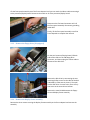
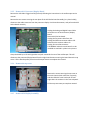
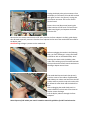
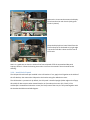
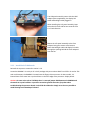
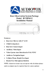
©2015 SIMMCONN LABS, LLC. All rights reserved
NewScope-T1 Operation
Manual
For Kits with Main Board Serial Number T1001 and above
May 17, 2015
NewScope-T1 Operation Manual
1
Introduction .......................................................................................................................................... 3
2
Installation ............................................................................................................................................ 4
3
2.1
Initial Inspection ............................................................................................................................ 4
2.2
Installation of the NewScope-T1 Kit ............................................................................................. 4
2.2.1
Prepare the unit for installation............................................................................................ 4
2.2.2
Remove the front-panel assembly ........................................................................................ 4
2.2.3
Remove the floppy drive (if equipped) ................................................................................. 5
2.2.4
Remove the display-frame assembly .................................................................................... 5
2.2.5
Remove A11 Processor/Display Board.................................................................................. 6
2.2.6
Remove the top cover ........................................................................................................... 6
2.2.7
Remove A30 Display Assembly ............................................................................................. 6
2.2.8
Install the LCD panel ............................................................................................................. 8
2.2.9
Install the LCD kit boards ...................................................................................................... 9
2.2.10
Finishing installation ........................................................................................................... 11
Operations .......................................................................................................................................... 12
3.1
Intensity controls ........................................................................................................................ 12
1 Introduction
The NewScope-T1 Color LCD replacement Kit is designed to replace the color CRT displays used in
Tektronix® TDS 500, 600 and 700 series digital oscilloscopes. The Kit supports 6.5” TFT color LCD at VGA
(640 x 480) resolution. The key features of the Kit include:
•
•
•
•
•
•
•
Digitally reproduces all the original colors designed for the CRT
Supports individual intensity adjustment of the display elements
Supports Insta-Vu, DPO, highlighted and persistence waveform display
Symmetric mounting bracket to allow different viewing direction preferences
Easy installation, no soldering required
Standard LCD panels with long-life, high brightness LED backlight
Does not use the rear VGA output port, free from A-to-D conversion background noise
Figure 1 NewScope-T1 Kit shown with highlighted four channel waveform display
2 Installation
2.1 Initial Inspection
Refer to Table 1 for a list of parts included in the NewScope-T1 Kit. Verify that all parts listed are
included in your kit. Note: items 5 through 9 are pre-assembled together as LCD panel assembly.
Table 1 NewScope-5 Kit Content
Item
1
2
3
4
5
6
7
8
8
9
Qty
1
1
1
1
1
1
1
1
1
4
Reference
NewScope-T1
PowerPlug-B
18-0001-001
18-0001-005A
18-0001-003
19-0001-008
LVDS_ADP
Description
Main board, NewScope LCD Kit
Power Supply (Butterfly) Board
Display Link Cable, LVDS, 20-Conductor, Shielded
Sync Cable, 5 Conductor
Back light Cable, 2 Conductor
LCD Mounting Bracket, 6.5 Inch
LCD Panel, 6.5 Inch
LVDS adapter, for TTL LCD panels only
LCD Panel gasket
M2 x 3mm Pan-head T5 screw
Note
2.2 Installation of the NewScope-T1 Kit
Installation should be performed by a qualified technical person who is familiar with the host test
equipment.
The Kit installation time is approximately 30 minutes. Please refer to test equipment service manuals for
location of the assemblies.
Caution: CRT could have lethal voltage on the anode. Use proper precautions when handling CRT
Assembly.
Note: Dispose of display within your state’s hazardous materials guidelines for CRT’s and electronics.
2.2.1 Prepare the unit for installation
Disconnect AC power cord. Remove the rear cover and cabinet from the equipment. Follow the
manufacturer’s ESD precaution guidelines in the unit’s service manual.
Remove the front trim ring. When removing the trim ring, grasp its back edge and vigorously flex it
upward before pulling it forward.
DO NOT touch the carbon contact points on the menu buttons installed in the trim ring. Also, do not
touch the exposed contacts on the flex circuit when you remove the trim ring.
2.2.2
Remove the front-panel assembly
Lift the front-panel assembly out of the front subpanel until you can reach the ribbon cable connecting it
to the processor/display board. Disconnect that cable at J2 of the processor/display board.
Disconnect the flex-board connector at P3 of
the front-panel assembly. Disconnect grounding
cable W76.
Finally, lift the front-panel assembly out of the
front subpanel to complete the removal.
2.2.3
Remove the floppy drive (if equipped)
On the A11 Processor/Display board, lift both
ends of the slider on the J38 floppy drive
connector, and then unplug the ribbon cable to
disconnect the disk drive.
Remove the disk drive by unscrewing the two
retaining Phillips screws on the sides of the disk
(indicated by red arrows in picture). Then pull
out the disk drive. On some units, there is only
one screw at the screw driver location.
Remove the metal shield between the floppy
drive and display-frame assembly.
2.2.4 Remove the display-frame assembly
Remove the three screws securing the display-frame assembly to the front subpanel and remove the
assembly.
2.2.5 Remove A11 Processor/Display Board
Remove the A29 Video Trigger board (if present) following the instructions in the oscilloscope service
manual.
Remove the two screws securing the rear plate of the A23 SerPar board assembly (or a place holder),
disconnect the cable connector from the processor-display circuit board connector, and pull out the A23
SerPar Board assembly.
Unplug the Analog and Digital Power Cable
connectors on the A11 Processor/Display
Board.
Remove A12 D1 bus board.
Unplug the fan power cable from J20.
Unplug the GPIB interconnect cable at J35.
Disconnect the monitor cable at J5.
Unplug J51 rear VGA connector.
The RAMDAC where the main board is to be
installed are marked in yellow in the picture.
Grasp the board by its left and right sides and pull it towards the rear of the oscilloscope. This will
disconnect the processor/display board from the eight board mounts securing the board above the top
cover. Lift the board up away from the oscilloscope chassis to complete the removal.
2.2.6
Remove the top cover
Remove the screws securing the top cover to
the main chassis (with red circles in picture),
and then slide the cover back until its front
edge clears the retainers in the front subpanel.
Lift the top cover away to complete removal.
2.2.7
Remove A30 Display Assembly
Unplug the display tube yoke connectors from
the display circuit board (J170 and J305 marked
with green circles in the picture). Unplug the
LCD shutter connector J570 on the smaller
vertical board.
Loosen the screw (blue arrow) securing the
video board to the CRT neck. Pull back on the
video board slightly and separate the board
from the CRT.
Remove the two screws that secure the CRT safety band to the front subpanel. Carefully guide display
tube forward to partially remove it from the front subpanel and to access the anode lead connected to
the display tube.
CAUTION! High-voltage is present on the anode lead.
Before unplugging the anode in the following
step, you must discharge it: using a flat-blade
screwdriver with an insulated handle, while
touching the chassis with the blade, probe
under the insulating cap of the anode lead with
the tip and touch the lead’s metal conductor to
discharge. Repeat several times.
The anode lead has two hooks (see picture).
Push the center of the rubber cap downward
and sideways to release one hook from the CRT
anode, and then push the cap to the other side
to release the other hook and the lead will be
free.
After unplugging the anode lead, touch its
metal conductor to the chassis a few times to
further ensure discharge.
Pull the display tube out through the front
subpanel.
Note: Dispose of CRT within your state’s hazardous materials guidelines for CRT’s and electronics.
Remove the six screws that mount the displaydriver board to the main chassis (with green
circles in picture).
Grasp the display driver board. Work from the
front and top to tilt the board so its right edge
is up and its left side is down and lift it out of
the chassis.
Now it is a good time to clean the inside of the front-subpanel off of the accumulated dust with
isopropyl alcohol. Follow the cleaning instructions in the service manual if the unit needs further
cleaning.
2.2.8 Install the LCD panel
The LCD panel should come pre-installed in the LCD bracket. If not, apply the LCD gasket to the inside of
the LCD bracket, then mount the LCD panel to the bracket using four M2x3mm screws.
The LCD bracket is symmetrical. By default, the LCD panel is installed upright (wider edge on the floppy
drive side) for best contrast when viewed head-on or from above the screen (12 o’clock). If the
oscilloscope is viewed from below the screen (6 o’clock) most of the time, the LCD panel together with
the bracket should be turned 180 degrees.
The LCD panel assembly comes with the LVDS
adapter (where applicable), the display link
cable and backlight cable plugged in.
When installing the LCD panel assembly, keep
this end on the left side for best contrast from
12 o’clock direction.
Mount the LCD panel assembly to the front
subpanel using two screws at the bottom.
Route the backlight cable and display link cable
through the opening behind the front subpanel
near the fan.
2.2.9 Install the LCD kit boards
Reinstall the top cover removed in section 2.2.6.
Locate the RAMDAC. It is a 44-pin IC in PLCC package with part number ADV471 or BT471. On earlier TDS
color oscilloscopes, the RAMDAC is located near the floppy drive connector. On later models, it is
located close to the metal can crystal oscillator on the front edge of the processor- display board.
Caution: On some units such as TDS784A, there is a two-pin jumper J502 between the RAMDAC and
the metal can crystal oscillator. It provides convenient ground connection for probes when
troubleshooting the processor board. It should be de-soldered or simply cut as short as possible to
avoid shorting to the NewScope-T1 board.
Align the PLCC socket on the NewScope-T1
board with the RAMDAC using the chamfered
corner. Put thumbs on top of the T1 board.
With other fingers supporting the processordisplay board from the back, apply even force
and snap the NewScope-T1 board onto the
RAMDAC. Install the T1 board firmly until you
feel a ‘click’ when the RAMDAC reaches the
bottom of the PLCC socket. Do not apply
excessive force beyond that.
Reinstall the A11 processor- display board by reversing steps in section 2.2.5.
While pressing the T1 board in place with one
hand, plug the display link cable connector to
the T1 board P2 with another hand. This is to
avoid the T1 board from dislodging from the
RAMDAC due to the insertion force of the
display link cable connector.
Connect the back light cable to P1 on the Power
Supply board. When installing the Power Supply
board to J5 of the A11 display-processor board,
first close the locking levers half-way. Make
sure the receptacle is aligned with the header
pins in J5, and then push the receptacle into J5.
Close the locking levers to complete the
installation.
Connect the Sync Cable from Power Supply
board P2 to main board P1. Note pin 1 of the
Sync Cable connector (marked with a white dot)
should be near U2.
Alternatively, the T1 main board may be
installed with the display link cable attached
and after the A11 processor- display board has
been put back in place. Rock the T1 board
slightly left and right when plugging in, until the
PLCC connector has been fully seated on top of
the RAMDAC IC.
2.2.10 Finishing installation
Remove the protective shipping film from the
LCD panel assembly.
Remove the protective paper backings from the
anti-glare acrylic sheet. Put the acrylic sheet on
top of the LCD panel bracket with the matte
side out.
Reinstall the display-frame assembly by
reversing the steps in section 2.2.4.
Reinstall the floppy drive (if equipped), the front-panel assembly and the trim ring by reversing the steps
in sections 2.2.3 and 2.2.2.
When reinstalling the cabinet, be careful not to catch or pinch the Sync Cable.
Reinstall the cabinet and the rear cover to complete the installation.
3 Operations
3.1 Intensity controls
The intensity controls work as before. The LCD back light brightness is determined by the intensity
settings of waveform and text, whichever is higher. By reducing the back light brightness, the life of the
backlight LED may be further extended.
Revision History
Revision
1.0
1.1
Date
Notes
4/27/2015 Initial revision for serial numbers T1001 and above
5/17/2015 Updated CRT anode lead removal procedure
Fixed sync cable pin 1 location (to be near U2)
Updated intensity control to remove the backlight intensity control limitations