1
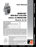
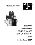
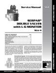
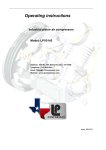
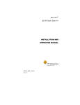
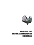
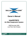
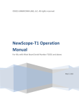
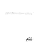
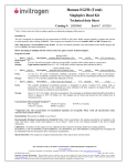
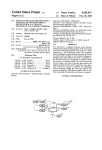
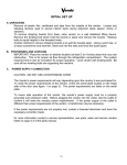
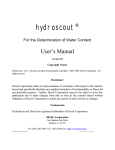
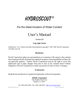
ROSS CONTROLS
®
SERPAR®
CROSSFLOW
DOUBLE VALVES
with D-S MONITOR
Service Manual W358C
TABLE OF CONTENTS
Page
INTRODUCTION.............................................................................................2
VALVE OPERATION
Normal Valve Operation...........................................................................3
Valve Conditions Resulting From a Malfunction..................................4
INSTALLATION NOTES..................................................................................5
TEST PROCEDURE.......................................................................................6
MAINTENANCE..............................................................................................6
TROUBLESHOOTING....................................................................................7
REPAIR PROCEDURES........................................................................... 8-11
CAUTIONS....................................................................................................11
WARRANTY..................................................................................................12
INTRODUCTION
The SERPAR® Crossflow double valve has two main valve
elements that move quickly and simultaneously during
normal operation. If either valve element fails to move or
moves too slowly, the D-S monitor is designed to detect this
condition. It then disconnects the electrical power to the
pilot solenoids, thereby inhibiting further valve operation.
The valve is then said to be “locked out” and cannot return
to normal operation until the monitor is reset. A lock-out
is not necessarily an indication that the valve has become
faulty. Rather, it is an indication that the monitor has
detected slow movement of one or both of the main valve
elements, and that there is a condition in the system that
needs correction.
The SERPAR® Crossflow double valve with D-S monitor
consists of four interconnected assemblies as shown inthe
illustration below.
Pilot Assembly – Consists of two 3/2 normally closed,
solenoid-controlled pilot valves in a single housing. Each
pilot valve controls one of the valve elements in the valve
body assembly.
Valve Body Assembly – A valve body having parallel
flow paths including two in-to-out crossflow paths, two 3/2
normally closed poppet valve elements, plus spool elements
to control air flow in the crossflow passages. A silencer is
bolted directly to the exhaust port.
Pressure Indicator Assembly – Contains two pistons
actuated by monitoring air pressures.
D-S Monitor Assembly – Consists of an encapsulated
electronic module with two proximity switches, monitoring
circuitry, and a terminal strip, all enclosed in an aluminum
housing.
2
ROSS CONTROLS®
NORMAL VALVE OPERATION
CONDITIONS AT START
Inlet air is blocked from the outlet by the two normally closed
valve elements “A” and “B” (see Figure 1). The outlet port
2 is connected to the exhaust port 3. Pilot supply air is
carried via passage 4 and supplies the two 3/2 normally
closed, solenoid controlled pilot valves “F”.
SOLENOIDS ENERGIZED
Simultaneously energizing the two solenoids “a” and “b”
(see Figure 2) causes the two pilot poppets “E” to shift
and close pilot exhaust passages. The open pilots allow
pilot air to move via passages 5 to the main valve piston
poppets “J”. Pressure on the piston poppets causes the
main valve elements to shift, closing off exhaust port 3.
At the same time, the inlet port 1 is opened to outlet port 2
via crosflow passages 10 and 11.
As the main valve poppets “U” and “V” open, monitoring
passages 6 are opened to inlet pressure. This pressure is
directed to the two pressure indicator pistons “K” and “L”
via monitoring air passages 6. As the pistons are actuated,
the indicator pins “C” and “D” extend into the magnetic
fields of the proximity switches “W” and “X”. Signals from
the proximity switches are interpreted by the monitor’s
circuitry. Because each pair of solenoids, pilot valves, main
valve elements, and pressure indicators has responded in
unison, the signals generated by the proximity switches
”W” and “X” will also be in unison. The monitor then reads
these signals as “normal valve operation.”
Figure 1 — Solenoids Not Energized
SOLENOIDS DE-ENERGIZED
Simultaneously de-energizing solenoids “a” and “b” allows
the two pilot poppets “E” to return to their normally closed
positions. Pilot pressure on the main valve pistons “J” is
exhausted through the main exhaust port 3 via internal
exhaust passages. Main valve piston poppets “J” and
inlet poppets “U” and “V” return to their normal positions.
Main valve inlet air is again blocked by poppets “U” and
“V”. Pressure at outlet port 2, at pressure indicator
pistons “K” and “L,” and in monitoring passages 6 is
exhausted through exhaust port 3. This completes the
normal operating cycle, and the valve is returned to the
CONDITIONS AT START described above.
Figure 2 — Solenoids Energized
www.rosscontrols.com
3
VALVE CONDITIONS RESULTING FROM A MALFUNCTION
DURING A MALFUNCTION
Due to a mechanical or electrical malfunction, one of the valve
elements may not respond to the energizing signal, or alternatively,
may not return to its normal position after the signal is removed. In
either case, there is a condition such as depicted in Figure 3 — one
valve element closed and one open. Inlet air flowing past open inlet
poppet U and into crossflow passage 10 is practically blocked by
spool H on valve element “B”. Although some air can pass around
spool ”H”, the amount is so small and the exhausting capacity of
the valve so large that the pressure at outlet 2 will not exceed two
percent of inlet pressure.
At the same time a monitoring air signal to pressure indicator K via
passage 6 causes the indicator pin “C” to be extended and actuate
proximity switch W. When the time interval between the signal to
a solenoid and the signal from its corresponding proximity switch
exceeds the design limit of approximately 175 milliseconds, the D-S
monitor will break the solenoid supply circuits as soon as solenoid
power is removed. Therefore, the solenoids cannot be re-energized
and the valve is made inoperative. The valve is said to “locked
out” because it cannot be returned to normal operation until the D-S
monitor is reset.
If the exhaust silencer becomes clogged, the valve elements may
move more slowly than normal. The monitor will detect this condition
and produce a lockout even though the valve elements may be moving
simultaneously as they should. It does this by measuring the time
interval between the signal to each solenoid and the signal from the
corresponding proximity switch, both on actuation and deactuation. If
this interval exceeds 175 milliseconds, the monitor breaks the supply
circuits to the solenoids, thereby producing a lockout. Note that on
actuation the lockout does not occur until solenoid power is removed.
Figure 3 – Faulted Mode: One Valve
Element Open and One Closed
Terminals are provided on the monitor for the connection of an
external fault indicator (see Figure 5). The fault indicator terminals
are internally connected when a lockout occurs or when power for
the monitor is interrupted.
FOLLOWING A LOCKOUT
With the electrical circuits to the solenoids broken by the lockout,
the pilot poppets “E”, the main inlet poppet “U”, and the pressure
indicator piston “K” return to their deactuated positions. Inlet
pressure is thereby completely blocked from the outlet. However,
if an inlet poppet remains open or partially open (perhaps due to
foreign material on the poppet seat), outlet pressure remains at no
more than two percent of inlet pressure. The smallness of this outlet
pressure is due to the blocking effect of the spools “G” and “H”, plus
the large exhausting capacity of the valve.
RESETTING THE D-S MONITOR
Following a lockout, the monitor must be reset before another
valve cycle can be initiated. To reset the monitor, an external reset
switch must be momentarily closed, then opened. Reset will occur
after a delay of approximately two seconds. However, as a safety
precaution, reset cannot occur if the solenoid supply circuits are
energized (voltage greater than 4.0 volts).
Reset can also be accomplished by momentarily interrupting the
power supply to the monitor.
CAUTION: Interrupting power to the monitor will accomplish a reset
whether or not the supply circuits to the solenoids are energized. If
reset is to be performed in this way, care must be taken to be sure
that the solenoids are de-energized so that the valve does not
immediately cycle and produce a potentially hazardous condition.
4
ROSS CONTROLS®
Figure 4 – All Elements Returned to
De-actuated Positions After Lockout,
but Electrical Supply Circuits Remain Open
INSTALLATION NOTES
Pneumatic equipment should be installed only by persons
trained and experienced in the installation of such
equipment.
Air Lines. Before installing a ROSS double valve in an
existing system, the air lines must be blown clean of all
contaminants in the system. Experience has shown that
one of the leading causes of lockouts is foreign material
from the air lines which becomes lodged in the valve. It is
strongly recommended that an air filter be installed ahead
of and close to the double valve.
Valve Inlet 1. See Figure 6. DO NOT RESTRICT AIR
SUPPLY. Any restriction of the air supply lines (for example,
sharp bends or undersized lines) will reduce the speed with
which the outlet volume is pressurized. A restricted air
supply can produce nuisance lockouts. See Inadequate
Air Supply, page 8.
Valve Outlet 2. For faster pressurizing and exhausting
of the outlet volume, locate the valve as close as possible
to the mechanism being operated. Also, avoid restrictions
in the outlet lines.
Valve Exhaust 3. DO NOT RESTRICT THE EXHAUST.
Limiting the exhausting speed decreases an important
safety feature of the double valve. During a malfunction
in which only one of the valve elements has shifted, air
escaping past the spool in the valve stem of the closed
valve element (see Figure 4) must be quickly exhausted
to keep outlet pressure at or below two percent of inlet
pressure. Therefore, only a properly sized and designed
silencer should be used. See CAUTION on page 9.
on the label affixed to the pilot housing. A supply voltage
that does not fall within this range can cause nuisance
lockouts or premature solenoid burnout. If electrical
power is supplied by a transformer, it should be capable
of handling the inrush current of the solenoids without a
significant voltage drop.
Power is supplied to solenoid “a” via terminals ”A” and “B”
(see Figure 5 below), and to solenoid “b” via terminals “C”
and “D”. The solenoids may be wired independently or in
parallel. The solenoid voltage should match the monitor
voltage.
Monitor Electrical Supply. Power is supplied via
terminals ”E” and “F”. A label on the monitor gives the
electrical power requirements: 120 VAC or 24 VDC.
Monitor Reset. An external switch for the reset function
is connected to the monitor at terminals “G” and “H”. The
reset switch should be normally-open & momentary.
CAUTION: Do NOT apply power to the reset terminals
”G” and “H”. To do so would damage the monitor.
Fault Indicator. An external fault indicator (a light,
for example) can be connected through terminals “J”
and “K”. These terminals are internally connected when
the monitor is faulted or when monitor power is off. A
maximum current of 5 amperes is allowable through
these terminals.
Mounting Position. It is recommended that double
valves be mounted with the pilot assembly at the top
whenever possible.
Pressure Range. The SERPAR® Crossflow double
valve with D-S monitor has an operating inlet pressure
range of 30 to 100 psig (2 to 7 bar). Pressure below
30 psig (2 bar) will reduce the speed of pressurizing the
outlet line, and can cause the valve elements to respond
erratically, and lead to intermittent lockouts. Pressure
above 100 psig (7 bar) will produce excessive poppet
impact during operation, thereby shortening the life of
the valve.
Temperature Range. The operating media (usually
air) tem-perature range is 40°F to 175°F (4°C to 80°C),
and the ambient temperature range is 40°F to 120°F
(4°C to 50°C). Shortening of valve life can result if these
temperature limits are not observed.
Solenoid Electrical Supply. It is very important that the
electrical supply match the voltage and frequency of the
monitor supply. ROSS solenoids are rated for continuous
duty at 85 percent to 110 percent of the voltage shown
www.rosscontrols.com
Figure 5 – D-S Monitor;
120 VAC Unit Illustrated;
24 VDC Unit also Available.
5
TEST PROCEDURES
ROSS valves are tested after assembly to assure proper
operation, but it is recommended that the following tests
be made when the valve is initially installed, or whenever
the valve has been disassembled. These tests should be
made at the repair bench and at the installation. At the
installation, take normal press operation safety precautions
during these tests to avoid the potential for personal injury
or damage to equipment. All tests should be performed
only by persons trained and experienced in the testing of
pneumatic equipment.
Before beginning these tests, make the electrical connections
outlined in the Installation Notes on page 5. These tests
call for the use of the manual overrides. If your valve is
not so equipped, use the corresponding solenoids instead.
This will require wiring the solenoids so that they can be
individually energized. If the valve fails any of the following
tests refer to Troubleshooting on page 7.
1. Remove silencer. Apply compressed air in the 30 to
100psig (2 to 7 bar) range to inlet port 1 (see Figure 6). There
should be no pressure at outlet port 2 or exhaust port 3.
2. Connect outlet port 2 to a small volume (25–50 cubic
inches) fitted with a damped pressure gauge. Simultaneously
energize both pilot solenoids. Inlet and outlet pressures
should be equal. There should be no leakage at the exhaust
port. De-energize both solenoids.
3. Simultaneously energize both pilot solenoids, then
depress manual override “N” (Figure 6). De-energize both
solenoids while holding override “N” depressed. There
should be a small flow of exhaust air. Release the manual
override. Exhaust air flow should stop.
4. Try to energize both pilot solenoids. The procedure
instep 3 should have caused the D-S monitor to lock out
sothat it is not possible to energize the solenoids. No
pressure should appear at either the outlet or exhaust port.
Turn off the electrical supply to the pilot solenoids.
5. Reset the monitor (see page 5). Simultaneously
energize both pilot solenoids. Inlet and outlet pressures
should be equal. There should be no leakage at the exhaust
port. De-energize both solenoids.
6. Simultaneously energize both pilot solenoids, then
depress manual override “P”. De-energize both solenoids
while holding override “P” depressed. There should be a
small flow of exhaust air. Release the manual override.
Exhaust air flow should stop.
7. Try to energize both pilot solenoids. The procedure
instep 6 should have caused the D-S monitor to lock out so
that it is not possible to energize the solenoids. No pressure
should appear at either the outlet or exhaust port. Turn off
the electrical supply to the pilot solenoids.
8. Repeat step 5.
9. Re-install silencer. Valve is ready for normal operation.
MAINTENANCE
Pneumatic equipment should be maintained only by persons
trained and experienced in the maintenance of such equipment.
Supply Clean Air. Foreign material lodging in valves is a
major cause of breakdowns. The use of a 5-micron-rated
air filter located close to the valve is strongly recommended.
The filter bowl should be drained regularly, and if its location
makes draining difficult, the filter should be equipped with
an automatic drain.
Check Lubricator Supply Rate. A lubricator should put a
fine oil mist into the air line in direct proportion to the rate
of air flow. Excessive lubrication can cause puddling in
the valve and lead to malfunctions. For most applications
an oil flow rate in the lubricator of one drop per minute
is adequate. (Note that the double valve itself does not
require air line lubrication.)
Compatible Lubricants. Although this valve does not require air line lubrication, it may be used with lubricated air
being supplied to other mechanisms. Some oils contain
additives that can harm seals or other valve components
and so cause the valve to malfunction. Avoid oils with
phosphate additives (e.g.,zinc dithiophosphate), and diester
oils; both types can harm valve components. The best
oils to use are generally petroleum base oils with oxidation
inhibitors, an aniline point between 180°F (82°C) and 220°F
(104°C), and an ISO 32 or lighter viscosity.
Some compatible oils are listed above at the right. These oils,
although believed to be compatible, could change without
notice because manufacturers sometimes reformulate their
oils. Therefore, use oils specifically compounded for air line
service. If it is a synthetic oil, contact the oil manufacturer
for compatibility information.
Cleaning the Valve. If the air supplied to the valve has not
been well filtered, the interior of the valve may accumulate
6
COMPATIBLE LUBRICANTS
MAKER
BRAND NAME
Amoco............................. American Industrial Oil 32
Amoco Spindle Oil C
Amolite 32
Citgo................................ Pacemaker 32
Exxon............................... Spinesstic 22
Teresstic 32
Mobil................................ Velocite 10
Non-Fluid Oil.................... Air Lube 10H/NR
Shell................................. Turbo T32
Sun.................................. Sunvis 11; Sunvis 722
Texaco............................. Regal R & O 32
Union............................... Union Turbine Oil
dirt and varnish which can affect the valve’s performance.
Although very tolerant of dirty air, the valve may sometimes
need cleaning.
To clean the valve use any good commercial solvent
orkerosene. Do not use a chlorinated solvent or abrasive
materials. The former damages seals, and abrasives can
do permanent damage to metal parts. Before reassembling
the valve, lubricate all sliding surfaces with a grease such
as Dow Corning BR-2.
Electrical Contacts. In the electrical circuits associated
with the valve solenoids, keep all switches or relay contacts
in good condition to avoid solenoid malfunctions.
Replace Worn Components. In most cases it is not
necessary to remove the valve from its installation for
servicing. However, turn off the electrical power to the
valve, shut off the air supply, and exhaust the air in the
system before beginning any disassembly operation.
ROSS CONTROLS®
TROUBLESHOOTING
The SERPAR® Crossflow double valve with D-S monitor is
designed to monitor the outlet pressures of the main valve
elements, and the electrical signals to the solenoids. If the valve
elements move too slowly or fail to move simultaneously, the
monitor is designed to detect this condition, act to shut down the
valve, and thus inhibit further operation. This is called a “lockout,”
but is not necessarily an indication that the valve is faulty. Rather,
it indicates that the monitor has detected incorrect movement of
the main valve elements, and that there is a condition in the
system that needs correcting. Troubleshooting involves finding
and correcting the condition that caused the lockout.
Troubleshooting should be done only by persons trained and
experienced in the servicing of pneumatic equipment. If the
troubleshooting is done at the installation instead of the repair
bench, take normal press operation safety precautions to avoid
personal injury or damage to equipment.
The Troubleshooting Chart below can serve as a guide to locating
and correcting malfunctions. After the valve is repaired, it should
be tested by following the Test Procedure on page 6. If valve
operation is still abnormal, repeat the troubleshooting procedure
or call ROSS in the U.S.A. at 1-888-TEK-ROSS for assistance.
Figure
6 – External Ports and Overrides
N, P
C
1
2
3
13
Manual overrides
Reset Solenoid
Inlet Port
Outlet Port
Exhaust Silencer
Electrical Conduit Port
TROUBLESHOOTING CHART
If the valve locks out, look for the Symptoms described in the first column. Possible Causes are given in the second column,
and Repair Procedures in the third column. Repair Procedures are detailed on the following pages.
After repairs are made, follow the Test Procedure on page 5 before returning the valve to service.
REPAIR
SYMPTOMS
POSSIBLE CAUSES
PROCEDURES
Valve locks out intermittently.
Inadequate air supply volume
A
Inadequate voltage at one or both solenoids
B
Sluggish pilot valve
D
Main inlet poppet not sealing
G
Transient foreign material in valve
E
Varnish deposits in valve
H
Excessive lubrication
L
Dirty or undersize silencer
F
Leaking piston poppet seal
J
Leaking pressure indicator seal
K
Stuck indicator pin
M
Valve locks out on first cycle Consider all of the above possible causes
—
after monitor is reset.
Faulty solenoid
C
Leaking pilot poppet
D
Loose pilot cover
C
Monitor will not reset.
Metal particles activating proximity switch
N
Solenoid control circuit energized: voltage> 4.0 V
P
Jammed solenoid plunger
C
Stuck indicator pin
M
Transient foreign material in valve
E
Main inlet poppet not sealing
G
Faulty monitor
P
www.rosscontrols.com
7
REPAIR PROCEDURES
A
INADEQUATE AIR SUPPLY VOLUME
Even though the air supply pressure is in the
correct 2 to 7 bar (30 to 100 psig) range, the air
volume supplied can be too little. An inadequate air supply
volume causes an excessive pressure drop during valve
actuation. Pilot air supply is sufficient to unseat the main
valve elements, but the pressure drop resulting from filling
the outlet volume depletes the pilot air supply. The main
valve elements may be only partially actuated, or may
reach the fully actuated position more slowly than normal.
The lowered pilot pressure can also exaggerate the effects
of small differences in the operating characteristics of
pilots and valve elements so that the valve elements may
not move simultaneously.
Any of these abnormal movements of the valve elements
will be sensed by the D-S monitor and result in a lockout. A
marginal air supply may result in only intermittent lockouts,
but a severely restricted air supply can produce a lockout
on each valve cycle.
Check for very long, undersize, or pinched supply lines,
sharp bends, and restrictive fittings. All can reduce the air
supply volume. Of course, the air volume supplied can also
be insufficient if more pneumatic devices are connected to
a circuit than the compressor is designed to serve.
B
INCORRECT VOLTAGE AT SOLENOIDS
Solenoids are rated for continuous duty at 85
percent to 110 percent of the voltage shown on the
pilot housing. A supply voltage that does not fall within this
range can cause nuisance lockouts, premature solenoid
burnout, or impact damage.
To check the electrical supply, first remove the switch box
cover at the bottom of the valve. Attach voltmeter leads to
terminals “A” and “B” (see Figure 5). Read the voltmeter
while the solenoids are energized. Repeat for terminals “C”
and “D”. If the voltage falls below the allowable operating
range, the electrical supply is inadequate, even though the
supply voltage might be correct without the solenoid load.
A voltage that exceeds the allowable maximum can
cause premature solenoid burnout, loss of air gap due to
impact damage, or a stuck solenoid plunger. See Repair
Procedure C below.
C
FAULTY SOLENOID OPERATION
Before removing solenoids for inspection, check
the following:
Loose pilot cover Q (Figure 8). A loose pilot cover can
give the symptoms of a defective solenoid because it
prevents full travel of one of both pilot valves. However,
the valve can operate normally if manual actuation is used.
This is because the gap between solenoid and pilot valve
is closed by the pressure of manual actuation. If loose,
tighten the cover and check for normal valve operation.
Jammed solenoid plunger.
Great overheating or
delamination of the plunger can cause it to jam. A solenoid
with such damage must be replaced.
Defective solenoid coil. Check the resistance of each coil
with an ohmmeter. A coil is defective if resistance is zero
or infinite. The most common cause of solenoid burnout
is incorrect supply voltage. See Repair Procedure B. If
the coils are not defective, examine the solenoids for the
following conditions.
Broken shading coil. See “S”, Figure 7. Copper shading
coils reduce the solenoid’s tendency to buzz when operated
on alternating current. If a shading coil is loose or broken,
the solenoid must be replaced.
Wear that causes a loss of air gap. There must be a
small gap between the solenoid plunger and the field frame
when the solenoid is energized. See air gap 15, Figure 7. If
significant wear is apparent in areas 16, the air gap can be
lost and the solenoid will buzz loudly when energized. With
this much wear, the solenoid should be replaced.
Lubrication will help to prolong solenoid life by preventing
some of the above troubles. Solenoids should be lubricated
periodically with a lithium based grease. Put grease on the
plunger and all impact surfaces.
D
FAULTY PILOT INSERT
Shut off electrical power to solenoids; shut off,
exhaust, and lock out the air supply. Disassemble
pilot section in the following way:
1. Remove pilot cover “Q” (Figure 8).
2. Slip leads off solenoid tab terminals and lift out both
solenoids. To check solenoids see Repair Procedure “C”.
3. Remove pilot body from valve body.
4. Remove rubber cushions “CA” from tops of pilot insert
assemblies.
5. With Truarc type pliers, remove retaining rings “CB”.
6. Remove inserts by grasping them at the shoulder area
and pulling with a circular motion. Removing inserts by
pulling on the spring or stem may damage the inserts.
7. Be sure that poppet return springs “CC” are remove
from insert cavity. Check action of each insert by pressing
lightly on the spring protruding from the top. It should
move easily with light finger pressure and should not jerk
or grab during its travel (approximately .03 inch). It does
not perform smoothly, the insert must be replaced.
16
S
If operation remains abnormal, turn off the electrical power
to the solenoids, remove the pilot cover, remove both
solenoids and check for the following:
8
ROSS CONTROLS®
15
Figure 7 – Solenoid
REPAIR PROCEDURES
Q
CA
CB
CA
CB
F
E
CC
9
5
F
E
CC
5
Figure 8 – Cross-section of Pilot Section
Inspect the poppets “E” and their seats for foreign particles or
damage. Carefully clean out foreign material. If the poppets
are swollen or have deteriorated, improper lubricants may
be the cause. Be sure to use only compatible lubricants as
described on page 6.
If a poppet or inlet (upper) seat is worn or defective, the
pilot insert must be replaced. Before installing a new insert,
blowout pilot air passages 5 and 9 to remove any loose dirt
particles.
E
TRANSIENT FOREIGN MATERIAL
If the valve resumes normal operation after
being reset, the cause of the lockout may have been
a transient foreign particle. A bit of scale or other foreign
material could lodge at various points in the valve to cause
a lockout. After resetting, the air flow of the next operating
cycle can “wash” the foreign material out so that the valve
continues to operate normally. This situation is most
common after a period of press inactivity. An efficient and
well maintained filter close to the valve can help to eliminate
this problem.
A stubborn bit of foreign material can also prevent the
monitor’s being reset. Using the manual overrides, cycle
the valve several times. If the monitor still cannot be reset, it
will be necessary to disassemble the valve for cleaning.
If a silencer other than the ROSS SERPAR® silencer is
used, be sure that it is of the correct capacity. Otherwise,
excessive back pressure may be immediately present and
cause sluggish operation of the valve. If a valve locks out
intermittently but performs normally when the silencer is
removed, clean the silencer or replace it with one of the
correct capacity.
G
MAIN INLET POPPET NOT SEALING
If one of the inlet poppets is not sealing, air can
be detected escaping at the exhaust port. Foreign
particles are sometimes responsible for holding a poppet
off its seat. Manually cycle the valve several times to see if
the flow of air through the valve will flush out the particles.
Take normal press operation safety precautions during this
procedure to avoid injury or damage to equipment. If cycling
does not clear the valve, it will be necessary to disassemble
and clean the valve.
To disassemble the valve, first turn off the electrical power
to the valve. Shut off, exhaust, and lock out the air supply.
Remove the pilot assembly, D-S monitor and housing, and
pressure indicator assembly.
ROSS expressly disclaims all warranties and responsibility
for any unsatisfactory performance or injuries caused by the
use of he wrong type, wrong size, or inadequately maintained
silencer installed with a ROSS product.
Disassembly Note. Before removing the pilot assembly
the solenoid leads must be slipped off the solenoid
terminals. When removing the monitor housing, exercise
care in with-drawing the solenoid leads from the passage
through the valve body. To remove the valve elements, first
remove the snap rings ”M” (Figure 9), end plugs “Y”, and
springs “Z” at the lower ends of the bores. Pull inlet poppets
“U” and “V” off the valve stems, and remove the remaining
parts of the valve elements through the top of the valve
body. If the inlet poppets “U” and “V” are damaged or have
deteriorated, replace them. Deteriorated poppet material
suggests the use of incompatible lubricants. Only lubricants
such as those described on page 6 should be used.
The silencer supplied with SERPAR® Crossflow double
valves is designed to create minimum back pressure.
However, after long usage with contaminant-laden air it
may become clogged. The increased back pressure can
then cause erratic motion of the valve elements and lead to
While the valve is disassembled, also inspect the piston
poppets J for damage or deterioration. Inspect the
bores for varnish deposits or excess wear. See Repair
Procedures H and J.
Lightly lubricate moving parts and re-assemble the valve.
F
UNDERSIZE or PLUGGED SILENCER
CAUTION: Restricting the exhaust port of a
double valve can adversely affect its operation and
create the potential for injury. Silencers must be resistant to
clogging and have a flow capacity greater than the exhaust
capacity of the valve. Silencers supplied by ROSS satisfy
these criteria.
intermittent lockouts. A dirty silencer should be removed and
cleaned with a water soluble detergent solution.
www.rosscontrols.com
9
REPAIR PROCEDURES
Figure 9 – Cross-section of Valve Body and Pressure Indicator Assembly
H
VARNISH DEPOSITS
Varnish deposits in the valve may affect the
movement of a piston and cause intermittent
lockouts. Varnish results from the action of oxygen on
lubricating oils and can be aggravated by excess heat.
Varnish can also come from overheated compressor oil
carried over into the air lines and deposited in the valve.
To disassemble for cleaning, first turn off electrical power to
the valve. Shut off the air supply and exhaust the air in the
system. Remove the pilot assembly, monitor and housing,
and pressure indicator assembly. See Repair Procedure K
and Disassembly Note in Repair Procedure G.
Use a water soluble detergent for cleaning varnished
areas. Avoid chlorinated solvents and abrasive materials.
The former can damage seals and poppets, and abrasives
can do permanent damage to metal parts.
Inspect all components for wear or damage.
lubricate moving parts before re-assembling.
Lightly
J
LEAKING PISTON POPPET SEAL
A worn or damaged piston poppet seal T (see Figure
9) can allow pilot pressure to leak past the piston
and cause erratic valve action and intermittent lockout.
Disassemble to inspect seals. See Disassembly Note in
Repair Procedure G. When installed, the seals should have
some compression in the bore. It is advisable at this time
also to inspect for varnish deposits, and wear or damage to
piston and inlet poppets and their seats.
Replace poppets and/or seals if damaged or worn. If the
seals show signs of deterioration, incompatible lubricants
or solvents may be the cause. See information about
compatible lubricants and cleaning on page 6.
K
LEAKING PRESSURE INDICATOR SEAL
A leaking pressure indicator seal “ PA” (see Figure 9)
can cause the pressure indicator to respond too slowly,
thereby causing a lockout. To disassemble for inspection,
first turn off the electrical powerto the valve. Shut off the
air supply and exhaust the air in the system. Remove
10
monitor and housing. See Disassembly Note in Repair
Procedure G. Remove end caps ”PB” and springs “PC” at
bottom of pressure indicator assembly. Pull out pressure
indicator pistons “K” and “L”, and inspect seals for wear or
damage. Also inspect piston bores for varnish deposits.
Clean bores and replace seals as necessary. Lightly
lubricate bores and re-assemble. Pistons should move
smoothly in bores when re-inserted.
L
EXCESSIVE LUBRICATION
Excess oil on the piston walls can sometimes
cause erratic valve action and result in intermittent
lockouts. Although lubrication is not required for this valve,
if a lubricator is used it should deposit only a thin film of
oil on the piston walls. Check lubricator in supply line; it
may be injecting too much oil for the existing rate of air
flow. Remove excess oil and re-assemble valve. Check
lubricator flow rate (see page 6).
M
STUCK INDICATOR PIN
If an indicator pin is stuck in the de-actuated
position, the monitor will lock the valve out on
the first cycle following reset. Each reset is followed
by a lockout. If an indicator pin is stuck in the actuated
position, the monitor will lock the valve out, but it will not be
possible to reset the valve. By removing the cover of the
monitor housing the movement of the indicator pins can be
observed as each of the manual overrides is depressed.
If either pin is stuck, it will be necessary to disassemble the
pressure indicator assembly. See Repair Procedure K for
disassembly instructions.
N
METAL PARTICLES IN MONITOR HOUSING
Whenever the monitor housing cover is removed,
care must be taken to prevent chips or other bits
of metal from entering the enclosure. Loose bits of metal
in the housing can trigger the proximity switches “W”
and “X”. This can cause one or both switches to remain
actuated so that themonitor will indicate a fault and will
not reset.
ROSS CONTROLS®
REPAIR PROCEDURES
P
MONITOR WILL NOT RESET
If the monitor indicates a fault but will not reset, the
monitor may be defective. However, all other possible
mechanical and electrical malfunctions should be checked
before concluding that the monitor is defective. Refer to
Repair Procedures C, G, M, and N particularly.
Verify that the solenoid control circuit is not energized. If it
is energized, the monitor cannot be reset. To be certain,
remove the monitor housing cover and check with a voltmeter
at terminals “A-B” (see Figure 5) and “C-D”. If a voltage is
present at either pair of terminals there is a defect in the
external solenoid control circuit.
Pull-down resistors (10K ohms, 2 watts) can be used
to eliminate leakage current from solid state switches.
Resistors would be connected across terminals “A-B”
and “C-D”.
With the solenoid control circuit de-energized, cycle the
valve several times by using the manual overrides. Take
normal press operation safety precautions during this test to
avoid personal injury or damage to equipment.
If the monitor cannot be reset, the monitor is defective and
must be replaced.
CAUTIONS
PRE-INSTALLATION or SERVICE
1. Before servicing a valve or other pneumatic component,
besure that the electrical supply is turned off, the entire
pneumatic system is shut off and exhausted, and all power
sources are locked out.
2. All ROSS products, including service kits and parts,
should be installed and/or serviced only by persons having
training and experience with pneumatic equipment. Because
any installation can be tampered with or need servicing after
installation, persons responsible for the safety of others or
the care of equipment must check every installation on a
regular basis and perform all necessary maintenance.
3. All applicable instructions should be read and complied
with before using any fluid power system in order to prevent
harm to persons or equipment. In addition, overhauled
or serviced valves must be functionally tested prior to
installation and use.
4. Each ROSS product should be used within its specification
limits. In addition, use only ROSS parts to repair ROSS
products. Failure to follow these directions can adversely
affect the performance of the product or result in the potential
for human injury.
FILTRATION and LUBRICATION
5. Dirt, scale, moisture, etc. are present in virtually every
air system. Although some valves are more tolerant of
these contaminants than others, best performance will be
realized if a filter is installed to clean the air supply, thus
preventing contaminants from interfering with the proper
performance of the equipment. ROSS recommends a filter
with a 5-micron rating for normal applications.
6. All standard ROSS filters and lubricators with
polycarbonate plastic bowls are designed for compressed
air applications only. Do not fail to use the metal bowl
guard, where provided, to minimize danger from high
pressure fragmentation in the event of bowl failure. Do not
expose these products to certain fluids, such as alcohol or
liquefied petroleum gas, as they can cause bowls to rupture,
creating a combustible condition, hazardous leakage,
and the potential for human injury. Immediately replace
a crazed, cracked, or deteriorated bowl. When bowl gets
dirty, replace it or wipe it with a clean dry cloth.
7. Only use lubricants which are compatible with materials
used in the valves and other components in the system.
Normally, com-patible lubricants are petroleum base oils
with oxidation inhibitors, an aniline point between 180°F
(82°C) and 220°F (104°C), and an ISO 32, or lighter,
viscosity. Avoid oils with phosphate type addi-tives which
can harm polyurethane components, potentially lead-ing
to valve failure and/or human injury.
AVOID INTAKE/EXHAUST RESTRICTION
8. Do not restrict the air flow in the supply line. To do
so could reduce the pressure of the supply air below the
minimum require-ments for the valve and thereby cause
erratic action.
9. Do not restrict a poppet valve’s exhaust port as this can
adversely affect its operation. Exhaust silencers must be
resistant to clogging and have flow capacities at least as
great as the exhaust capacities of the valves. Contamination
of the silencer can result in reduced flow and increased back
pressure.
ROSS expressly disclaims all warranties and responsibility
for any unsatisfactory performance or injuries caused by
the use of the wrong type, wrong size, or inadequately
maintained silencer in-stalled with a ROSS product.
POWER PRESSES
10. Mechanical power presses and other potentially
hazardous machinery using a pneumatically controlled
clutch and brake mechanism must use a press control double
valve with a monitoring device. A double valve without a
self-contained monitoring device should be used only in
conjunction with a control system which assures monitoring
of the valve. All double valve installations involving hazardous
applications should incorporate a monitoring system which
inhibits further operation of the valve and machine in the
event of a failure within the valve mechanism.
ENERGY ISOLATION/EMERGENCY STOP
11. Per specifications and regulations, ROSS L-O-X® and
L-O-X/EEZ-ON® products are defined as energy isolation
devices, NOT AS EMERGENCY STOP DEVICES.
www.rosscontrols.com
11
GLOBAL Reach with a LOCAL Touchsm
ROSS EUROPA® GmbH
ROSS CONTROLS®
Langen, Germany
Telephone: + 49-6103-7597-0
Fax: + 49-6103-74694
Email: [email protected]
www.rosseuropa.com
Troy, MI., U.S.A.
Telephone: + 1-248-764-1800
Fax: + 1-248-764-1850
In the United States:
Safety Department: 1-248-764-1816
Customer Service: 1-800-GET ROSS
(438-7677)
Technical Service: 1-888-TEK-ROSS
(835-7677)
www.rosscontrols.com
ROSS ASIA® K.K.
Kanagawa, Japan
Telephone: + 81-427-78-7251
Fax: + 81-427-78-7256
www.rossasia.co.jp
ROSS UK Ltd.
Birmingham, United Kingdom
Telephone: + 44-121-559-4900
Fax: + 44-121-559-5309
Email: [email protected]
ROSS CONTROLS (CHINA) Ltd
ROSS SOUTH AMERICA Ltda.
São Paulo, Brazil CEP 09725-020
Telephone: + 55-11-4335-2200
Fax: + 55-11-4335-3888
Email: [email protected]
Your local ROSS distributor is:
Shanghai, China
Telephone: + 86-21-6915-7951
Fax: + 86-21-6915-7960
Email: [email protected]
ROSS CONTROLS® INDIA Pvt. Ltd.
Chennai, India
Telephone: + 91-44-2624-9040
Fax: + 91-44-2625-8730
Email: [email protected]
DIMAFLUID s.a.s.
Saint Ouen, France
Telephone: + 33-01-49-45-65-65
Fax: + 33-01-49-45-65-30
Email: [email protected]
www.dimafluid.com
Warranty
Products manufactured by ROSS are warranted to be free of defects in material and workmanship for a period of one year
from the date of purchase. ROSS’ obligation under this warranty is limited to repair or replacement of the product or refund of
the purchase price paid solely at the discretion of ROSS and provided such product is returned to ROSS freight prepaid and
upon examination by ROSS such product is found to be defective. This warranty shall be void in the event that product has
been subject to misuse, misapplication, improper maintenance, modification or tampering. THE WARRANTY EXPRESSED
ABOVE IS IN LIEU OF AND EXCLUSIVE OF ALL OTHER WARRANTIES AND ROSS EXPRESSLY DISCLAIMS ALL
OTHER WARRANTIES EITHER EXPRESSED OR IMPLIED WITH RESPECT TO MERCHANTABILITY OR FITNESS
FOR A PARTICULAR PURPOSE. ROSS MAKES NO WARRANTY WITH RESPECT TO ITS PRODUCTS MEETING THE
PROVISIONS OF ANY GOVERNMENTAL OCCUPATIONAL SAFETY AND/OR HEALTH LAWS OR REGULATIONS. IN NO
EVENT SHALL ROSS BE LIABLE TO PURCHASER, USER, THEIR EMPLOYEES OR OTHERS FOR INCIDENTAL OR
CONSEQUENTIAL DAMAGES WHICH MAY RESULT FROM A BREACH OF THE WARRANTY DESCRIBED ABOVE OR
THE USE OR MISUSE OF THE PRODUCTS. NO STATEMENT OF ANY REPRESENTATIVE OR EMPLOYEE OF ROSS
SHALL EXTEND THE LIABILITY OF ROSS AS SET FORTH HEREIN.
Printed in the U.S.A. - Rev. 08/08
© 2007, 2008 ROSS CONTROLS®. All Rights Reserved.
Form SM057