1
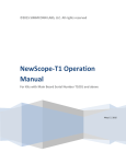
©2014 SIMMCONN Labs, LLC All rights reserved
NewScope-8 Operating
Manual
For Kits with Main Board Serial Number 8001 and above
March 31, 2015
NewScope-8 Operating Manual
1
Introduction .......................................................................................................................................... 4
2
Installation ............................................................................................................................................ 5
3
4
2.1
Initial Inspection ............................................................................................................................ 5
2.2
Installation of the NewScope-8 Kit ............................................................................................... 7
2.2.1
Read before installation ........................................................................................................ 7
2.2.2
Prepare the 85662A unit ....................................................................................................... 7
2.2.3
Remove the front panel ........................................................................................................ 7
2.2.4
Remove the metalized glass window .................................................................................... 8
2.2.5
Replace the Front Bezel (required if the kit comes with a modified bezel).......................... 9
2.2.6
Remove the XYZ driver boards (Optional) .......................................................................... 10
2.2.7
Remove the CRT and high voltage module ......................................................................... 10
2.2.8
Install the NewScope-8 main board .................................................................................... 11
2.2.9
Wire connections on the 85662A main board .................................................................... 13
2.2.10
Install the Power Plug board ............................................................................................... 14
2.2.11
Install LCD panel and 85662A Bridge board (5.7” VGA Kit) ................................................ 14
2.2.12
Install LCD panel (6.5” VGA Kit) .......................................................................................... 16
2.2.13
Install LCD panel (6.5” XGA Kit) ........................................................................................... 16
2.2.14
Finishing installation ........................................................................................................... 16
Operations .......................................................................................................................................... 17
3.1
Intensity control .......................................................................................................................... 17
3.2
Focus control ............................................................................................................................... 17
3.3
Align control ................................................................................................................................ 17
3.4
Display on/off control ................................................................................................................. 18
3.5
LCD panel pixel geometry ........................................................................................................... 18
3.6
LEDs ............................................................................................................................................. 18
3.7
Jumpers ....................................................................................................................................... 18
3.8
Other Onboard Connectors ........................................................................................................ 19
Adjustment.......................................................................................................................................... 19
4.1
Zero-Span Fast Sweep Vertical Adjustment ................................................................................ 19
2
4.1.1
Equipment Needed ............................................................................................................. 19
4.1.2
Adjustment Procedure ........................................................................................................ 20
3
1 Introduction
The NewScope-8 Color LCD replacement Kit is designed to replace the monochrome CRT in the HP®
85662A spectrum analyzer display. The Kit may be equipped with 5.7”, 6.4”, 6.5” or 7” TFT color LCD
with VGA (640 x 480), XGA (1024 x 768) or WXGA (1280x800) resolutions. The key features of the Kit
include:
•
•
•
•
•
•
•
Bitmap font with hand-optimized glyphs gives better clarity over the original vector font when
rendered on a raster LCD panel.
Enlarged marker in distinct shape and color.
Resolution enhancement takes advantage of the 1024 point original resolution of the 85662A
display and gives a smooth curve with reduced jaggedness.
Four display schemes selectable by the align pot
Sweeps of 10ms and below are now digitized and stored in trace A memory, which can be
captured via GPIB. The X axis is timed with a crystal oscillator that requires no adjustment.
Compatible with existing GPIB automation software.
The LCD backlight is powered from the source that was used for the CRT high voltage module.
Figure 1 NewScope-8 6.4” VGA Kit shown with default (NewScope) display scheme
4
2 Installation
2.1 Initial Inspection
Refer to the following tables for a list of parts included in the NewScope-8 Kit. Verify that all parts listed
are included in your kit. Note: items may differ with different LCD panel configurations.
Table 1 NewScope-8 5.7” VGA Kit Content
Item
1
2
3
4
5
6
7
Qty
1
1
1
1
1
1
1
Reference
NewScope-8
LVDS_ADP
Pwr_plg
85662A_Bridge
18-0001-018
18-0001-015
18-0001-019
8
9
1
4
18-0001-017
Description
Main board for VGA kit
Display Board (LVDS Adapter)
Power Plug board
85662A Bridge board
Display Link Cable, LVDS, 20-Conductor
Display Board Control Cable, 6-Conductor
Power Plug Board Control Cable, 3Conductor
LCD Backlight Cable
#4 x 3/8” Pan-head Philips self-tapping
screw
5.7” LCD Panel
5.7” LCD Panel Bracket
Nylon Flat Washer, 3.5x7x1mm
M3x8 Flat-head Philips screw
6-32 x ½” Flat-head Philips Screw
6-32 KEP® Nut
Foam strip w/ adhesive backing, 10mm
2” Wire for LRTRC and FS connection
14” Wire for CRT_DSBL connection
Coax cable for Y connection
Nylon wire ties 4”
Note
Description
Main board for VGA kit
Display Board (LVDS Adapter)
Power Plug board
85662A Bridge board
Display Link Cable, LVDS, 20-Conductor
Display Board Control Cable, 6-Conductor
Power Plug Board Control Cable, 3 to 5Conductor
LCD Backlight Cable
Note
10
1
11
1
19-0001-011
12
4
13
2
14
2
15
2
16
1
17
2
18
1
19
1
20
2
Note:
1. Shipped pre-assembled as LCD panel assembly.
1
1
1
1
1
1
1
Table 2 NewScope-8 6.5" VGA Kit Content
Item
1
2
3
4
5
6
7
Qty
1
1
1
1
1
1
1
8
1
Reference
NewScope-8
LVDS_ADP
Pwr_plg
85662A_Bridge
18-0001-018
18-0001-015
18-0001-019
1, For TTL Panels only
1
Cable may differ
depending on LCD Panel
Cable may differ
5
9
1
CCFL Backlight Inverter, 12VDC
depending on LCD Panel
For 6.5” CCFL Panels
only
1
1
2
1
10
1
6.5” VGA LCD Panel
11
1
19-0001-012
LCD Panel Bracket
12
1
19-0001-013
Modified 85662A bezel for 6.5” LCD panel
13
4
M2 x 3 Pan-head T-6 screw
14
2
M3 x 8 Flat-head Philips screw
15
2
6-32 x ½” Flat-head Philips Screw
16
2
6-32 KEP Nut
17
2
2” Wire for LRTRC and FS connection
18
1
14” Wire for CRT_DSBL connection
19
1
Coax cable for Y connection
20
2
Nylon wire ties 4”
Note:
1. Shipped pre-assembled as LCD panel assembly.
2. The LCD panel assembly is installed on the 85662A bezel for shipping purpose. Please remove the LCD
panel assembly from the bezel for installation.
Table 3 NewScope-8 6.5" XGA Kit Content
Item
1
2
3
4
5
6
Qty
1
1
1
1
1
1
Reference
NewScope-8
Pwr_plg
85662A_Bridge
18-0001-008
18-0001-015
18-0001-019
7
1
Description
Main board for XGA/WXGA kit
Power Plug board
85662A Bridge board
Display Link Cable, LVDS, 20-Conductor
Display Board Control Cable, 6-Conductor
Power Plug Board Control Cable, 3 to 5Conductor
LCD Backlight Cable, 12 conductor
8
1
LED Backlight driver, 12VDC input
9
10
11
12
13
14
15
16
17
18
19
20
1
1
1
1
4
2
2
2
2
1
1
2
18-0001-021
19-0001-009
19-0001-013
LED Backlight driver cable, 6 conductor
6.5” XGA LCD Panel
LCD Panel Bracket
Modified 85662A bezel for 6.5” LCD panel
M2 x 3 Pan-head T-6 screw
M3x8 Flat-head Philips screw
6-32 x ½” Flat-head Philips Screw
6-32 KEP Nut
2” Wire for LRTRC and FS connection
14” Wire for CRT_DSBL connection
Coax cable for Y connection
Nylon wire ties 4”
Note
1
Cable may differ
depending on LCD Panel
1, Cable may differ
depending on LCD Panel
1, For Power Plug board
without LED driver
1
1
1
2
1
6
Note:
1. Shipped pre-assembled as LCD panel assembly.
2. The LCD panel assembly is installed on the 85662A bezel for shipping purpose. Please remove the LCD
panel assembly from the bezel for installation.
2.2 Installation of the NewScope-8 Kit
Installation should be performed by a qualified technical person who is familiar with the 85662A unit.
The Kit installation time is approximately 3 hours. Please refer to spectrum analyzer service manuals for
location of the assemblies.
2.2.1 Read before installation
Please treat the parts and assemblies with care during installation. Take the following guidelines when
installing the kit:
1) Do not use power tools to fasten screws. Use a manual screwdriver so that you can see and feel if
something is not well aligned. If you meet considerable resistance when fastening a screw, back off and
try again.
2) The connectors are fragile. If you meet resistance when trying to make a connection, wiggle the
connector gently left and right, let it find its way and then gradually plug in. Do the same when
disconnecting a cable.
3) Do not force anything into position. If something doesn't seem to fit, give it a little wiggle room and it
will likely correct itself.
4) Before you try to modify some part that doesn’t seem to fit, take a short break and read the manual
one more time. Chances are some steps in the manual may not be very clear or well understood. Ask
questions and we'll get back to you as soon as we can.
2.2.2 Prepare the 85662A unit
Disconnect AC power cord. Remove all cables connecting the 85662A IF section to the 8566/67/68 RF
section, separate the IF section from the RF section. Remove the top and bottom covers from the
85662A.
2.2.3 Remove the front panel
Refer to the 85662A service manual (HP part # 85662-90085) section A1A1 for procedures to remove
the front panel:
7
Remove the plastic trim strip on the top of the
unit by inserting a small flat screwdriver into
the slot and lifting upwards. Remove two
screws located under trim strip.
Remove adhesive trim strips from both sides of
instrument. Remove two screws located under
each trim strip. Remove all four screws, two on
each side.
Remove two screws from bottom of instrument
used to secure front panel to frame.
Pull front panel forward to separate from the
frame.
Disconnect the two 14-pin DIP ribbon cable
connectors from the motherboard sockets.
Disconnect the 50-pin ribbon cable connector
from the top edge of the A1A1 keyboard. Front
panel is now loose from instrument.
2.2.4 Remove the metalized glass window
Remove the two small screws from the bottom of the plastic CRT bezel.
With the front panel assembly on its back so the glass cannot fall out, gently pull the plastic CRT bezel
bottom forward until it clears the mounting tabs on the inner bezel casting, then slide it downward to
free its upper retaining tabs and remove it.
Carefully remove the metalized glass window from the inner bezel casting. Clean the glass with glass
cleaner.
8
2.2.5
Replace the Front Bezel (required if the kit comes with a modified bezel)
Loosen the set screws on the “Level” and
“Intensity” knobs using 0.050” hex wrench.
Remove the knobs and the retaining nuts
underneath them. Lift the front dress panel and
set it aside.
On some units, the front dress panel is taped to
the front subpanel. Remove the nine 4-40 panhead Philips screws and remove the front panel
PCB. Slowly separate the front dress panel from
the subpanel by pushing from the PCB side.
Remove the eight 4-40 flat-head screws on the
front of the front subpanel. Remove the
subpanel from the front bezel.
In the kit that you received, the LCD panel
assembly is installed in the bezel for shipping
purpose. It needs to be removed for
installation. (6.5” VGA panel assembly shown)
Undo the four screws on the top, bottom and
side of the bezel. Remove the LCD panel
assembly. Save the fasteners for installation.
9
Replace the original bezel with the modified
bezel. Install the subpanel and keyboard PCB
A1A1 to the new bezel. Replace the front dress
panel, retaining nuts, “Level” knob, and
“Intensity” knob.
Return the undamaged original bezel to the Kit
vendor to receive the core charge refund.
2.2.6 Remove the XYZ driver boards (Optional)
NOTE: If the XYZ output function is no longer needed, A1A2, A1A4 and A1A5 boards may be removed
from the unit. On some later model 85662A units, a single board replaces the A1A2, A1A4, and A1A5
boards. To retain the XYZ output function, no change is required to the above boards.
2.2.7 Remove the CRT and high voltage module
Warning! Potentially Lethal Voltages Present!
Review the 8566/67/68 service manual for safety guidelines, CRT warnings and high voltage power
supply warnings before proceeding.
Remove the A1A3 shielding cage cover. In older
85662A units, the A1A6/A7/A8 cage cover and
the A1C3 capacitor cover may also need to be
removed. They will be reinstalled later.
Remove the rear CRT mount.
10
Carefully discharge the CRT and high voltage
power supply.
Disconnect and remove the CRT as per the
8566/67/68 service manual.
Remove the four 6-32 screws securing the
A1A3 high voltage power supply and the
shielding cage to the mother board. Remove
the A1A3 high voltage power supply.
Separate the high voltage power supply from
the shielding cage. The A1A3 shielding cage can
be left loose in the unit with cable clips
attached. It will be installed later.
2.2.8
Install the NewScope-8 main board
On the top cover of the A3 card cage near the
SMB connectors, mark the color of the cables
for later installation.
Disconnect the three SMB cables that are
connected to the top of the A3 card cage.
Remove the top cover of the A3 card cage.
Remove A3A4 from the A3 card cage (the card
with YELLOW extraction levers).
11
Make two loops with wire ties. These will be
the extraction aid should you need to remove
the board later. Rest the loop in the PCB notch.
Feed the display link cable and display board
control cable through the venting holes into
the A3 card cage.
Plug the display board control cable (6conductor) to the NewScope-8 Main board
P19.
Plug the display link cable to the NewScope-8
Main board P2. Note the end with a white dot
aligns with the triangle on the PCB.
Install the main board into the A3A4 card cage
slot, route the display link cable and the display
board control cable between the A3 card cage
and the A1A3 shielding cage to the LCD panel
area.
Set Main board jumper P1 base on the orientation of the LCD panel. See section 3.5 LCD panel pixel
geometry.
Replace the A3 card cage top cover.
Reconnect the three SMB cables that were connected through the top cover of the A3 card cage.
12
2.2.9 Wire connections on the 85662A main board
Note: The signal names provided in parenthesis () in this section are for referencing to the HP service
manual. They may or may not be labeled on the PCB.
This is the overview of the wiring locations from
bottom of the unit.
Solder a 2” wire between A3XA2P2 pin 27 and
A3XA4P1 pin 6 (signal name LRTRC) on the
underside of the A3 motherboard.
Solder a 2” wire between A3XA2P2 pin 23 and
A3XA4P1 pin 24 (signal name FS).
Route a coax cable under the 50-pin ribbon
cable and solder the center conductor to
A3XA4P1 pin-8 (signal name Y) and the shield
(GND) to A3XA4P1 pin-26.
On the other end of the cable, solder the center
conductor to A3XA2P1 pin-4 and the shield to
A3XA2P1 pin-21 (located diagonally from pin-4).
13
Solder a 14” wire between A4XA9P1 pin 3
(signal name CRT_DSBL) and A3XA4P1 pin 1.
Run the wire under the 50-pin ribbon cable.
De-solder and discard the eight L-shaped pins that the CRT plugged into on the motherboard. This step
helps to prevent the pins from shorting to the instrument cover.
2.2.10 Install the Power Plug board
Plug the 6-pin end of the Power Plug Board
control cable on the Power Plug board. Install
the Power Plug board in A1XA3P1. Note that
pin 1 is facing the front of the unit.
Route the cable through the large round
opening on the A1A3 high voltage power supply
shielding cage. For older units without the large
round hole, work the connector through one of
the small round holes in the front and install
the grommet.
Reinstall the A1A3 shielding cage cover. Ensure
the display link cable and the display board
control cable pass in front of the A1A3 cage.
Engage cards A1A7 and A1A8 into their guide
slots if removed. Reinstall the A1C3 and
A1A6/A7/A8 covers if removed in step 2.2.6.
Reconnect all cable clamps that were
disconnected from the A1A3 and A1A6/A7/A8
assemblies.
2.2.11 Install LCD panel and 85662A Bridge board (5.7” VGA Kit)
Apply foam strips to four edges on the front side of the LCD panel. Remove the protective plastic
shipping film from the front of the LCD screen. Be careful not to scratch the LCD screen.
14
Place the LCD panel assembly face down into
the front bezel cavity for the CRT.
Connect the LCD panel backlight cable to the
LCD Panel.
Connect the Display Link Cable to the Display
Board (LVDS Adapter) mounted on the back of
the LCD panel.
Connect the Power Plug Board Control Cable,
Display Board Control Cable and LCD Backlight
Cable to the 85662A Bridge Board.
Plug the 85662A Bridge Board to the
motherboard A1J1.
Connect A1A1W1 to the 14-pin DIP socket on
top of the 85662A Bridge Board.
Re-connect the remaining front panel cables to
the 85662A by connecting the 50-pin ribbon
cable to the keyboard and the remaining 14-pin
DIP cable from the keyboard to A3J1.
Fit the front bezel back into the front frame.
Fasten the LCD mounting bracket using M3 flathead Philips screws on top and bottom (Green
Arrow in picture).
Fasten the front bezel using the ½” 6-32 screws
from the left side of the unit. Engage the KEP
nuts while feeding the screw. Tighten the
screws first, then the KEP nuts.
Install the remaining frame screws that were removed in step 2.2.2. Be careful not to pinch any cables
between the front panel and the frame.
15
Turn the unit face-up. Replace the EMI glass and the plastic CRT bezel removed in step 2.2.3.
2.2.12 Install LCD panel (6.5” VGA Kit)
On the 6.5” TTL panel, the Display Board (LVDS
Adapter) is very close to the lower side
mounting hole. Use the original mounting
screw and do not install the KEP nut at this
location.
Use the supplied ½” 6-32 screw and install the
KEP nut at the upper side mounting hole only.
Refer to previous section 2.2.11 for other
installation steps.
2.2.13 Install LCD panel (6.5” XGA Kit)
On the 6.5” XGA panel, the LVDS cable is very
close to the lower side mounting hole. Use
caution not to damage the wires when
installing the KEP nut.
Refer to previous section 2.2.11 for other
installation steps.
2.2.14 Finishing installation
Replace the bottom cover.
Turn the front panel intensity knob to the 12 o’clock position.
Reconnect the 85662A to the spectrum analyzer RF section with the interconnect cables. Reconnect AC
power.
Turn on spectrum analyzer and verify correct operation.
Replace top cover.
16
3 Operations
3.1 Intensity control
The intensity knob works as before. You may not be able to completely dim the backlight with the
intensity knob with LCD panels using CCFL backlight, due to the minimum operating current requirement
of the CCFL tube.
A noisy intensity pot may cause surges in the backlight operating current. It should be cleaned or
replaced. The intensity is set to max for the original CRT circuit.
3.2 Focus control
The Focus control does not have any effect to the NewScope display. The Focus pot voltage is forwarded
to the main board.
3.3 Align control
The Align control is used by the NewScope display to switch between display schemes. There are four
preset, user configurable display schemes. Turning the pot clockwise with a screw driver or a tuning tool
will change the display scheme from 1 to 4. The preset display schemes are listed in Table 2. The Align
control is set to center (0V) for the original CRT circuit.
Table 4 Default Display Schemes for 6.4” VGA Kit
Display Items
NewScope
8560EC
Sample picture
See Figure 1
See Figure 3
Background
Black
Black
Label
Cyan
White
Display Line
Orange
Orange
Marker
Red (Bitmap)
Red
Resolution Enhancement
Yes
No
Trace A
White
Yellow
Trace B
66% White
75% Cyan
Trace C
50% Yellow
75% Magenta
Graticule Lines
Green
50% Cyan
Graticule Style
Dotted*
Solid
Small Font (D1)
Bitmap+Vector Bitmap+Vector
Medium Font (D2)
Bitmap
Bitmap
Large Font (D3)
Bitmap+Vector Bitmap+Vector
Large Font (Bex)
Vector
Vector
*Dotted graticule is not available on 5.7” or 7” LCD Panels
Original Mono
See Figure 4
Black
Green
89% Green
White
No
Green
75% Green
63% Green
50% Green
Solid
Bitmap+Vector
Vector
Vector
Vector
Inverted
See Figure 5
White
Black
Orange
Red (Bitmap)
No
50% Green
Magenta
Blue
Green
Solid
Bitmap+Vector
Bitmap, Bold
Bitmap+Vector
Vector
17
Figure 2 8560EC Display Scheme
Figure 3 Original Display Scheme
Figure 4 Inverted Display Scheme
3.4 Display on/off control
Display-off and -on (shift-g and shift-h) still work as before. The backlight is turned off and the LCD
outputs blank screen when shift-g is pressed. Except for the display, the instrument operation is not
affected.
When shift-h is pressed, the NewScope display firmware is reinitialized. Shift-g and shift-h can be used
to reset the NewScope display in case of malfunction.
3.5 LCD panel pixel geometry
The Resolution Enhancement in the NewScope display scheme is sensitive to the LCD panel pixel
geometry. The jumper P1 pin 1-3 selects matching geometry for the best result. When the jumper block
is not installed, the NewScope display expects an R-G-B pixel order (from left to right). A jumper block
should be installed if the panel is installed with B-G-R pixel order.
The NewScope-8 Kit is shipped with correct jumper setting. If the user is not sure about the pixel order,
he/she should try a different setting if apparent color fringes appear on the sides of the graphic curves.
3.6 LEDs
There are two LEDs on the main board, D1 and D2. D1 serves as ‘activity’ LED. Its duty ratio roughly
indicates the display CPU utilization. The longer it stays on, the lower the utilization. D2 serves as ‘FPGA
configuration done’, indicating a successful FPGA configuration.
3.7 Jumpers
There are four jumpers on the NewScope-8 main board. Their usage is explained in Table 3
Table 5 Jumper Settings
Jumper
P1
Position
1-3
P3
2-4
1-3
On
Use alternate pixel
geometry
Reserved
5.7” LCD Panel
OFF
Use default pixel
geometry
Reserved
6.5” LCD Panel
Note
Refer to section 3.5
Set LCD panel configuration
18
2-4
Used for recovery from
unsuccessful firmware
update only
P17*
1-2
LCD image scan direction LCD image scan
Change LCD image scan
line #1 High
direction line #1 Low
direction.
Some LCD panels require
3-4
LCD image scan direction LCD image scan
installing both jumpers to
line #2 High
direction line #2 Low
rotate image 180°. Other
LCD panels require only
one jumper. If image
rotation is desired, try both
jumpers until display image
is satisfactory.
P20
1-2
Jumper installed on the right side
Use Digital (PWM) dimming
2-3
Jumper installed on the left side
Use Analog dimming.
Dimming type
(PWM/Analog) is set at the
factory to the LCD panel
requirement.
*P17 pin 5 and 6 are reserved for factory use. Do not change the factory setting.
3.8
Return to factory setting
Normal operation
Other Onboard Connectors
Other onboard connectors such as P10 and P12 are reserved for factory use. P12 may be used by
advanced users to update firmware and/or communicate to the main board. Its usage is described in the
NewScope-8 Programming Manual
4 Adjustment
4.1 Zero-Span Fast Sweep Vertical Adjustment
The zero-span with sweep speed 10ms or below is digitized and stored in the trace memory. The
horizontal sweep of the digitizing system is timed by a crystal oscillator and requires no adjustment. The
vertical gain and offset need to be adjusted in order to be consistent with the ADC in the 85662A.
The Zero-Span Fast Sweep Vertical adjustment should be performed after the Track and Hold
adjustments in the 8568/8566 Performance Tests and Adjustments Manual.
4.1.1 Equipment Needed
Any RF signal generator that is capable of generating AM modulated signal up to 90% modulation depth,
with output carrier frequency within the frequency range of the spectrum analyzer, such as HP® 8656B.
The modulating signal needs to be between 400Hz and 1KHz. It can be any kind of repetitive signal, such
as sine wave or square wave. An external audio signal generator is needed if the RF signal generator
does not have internal modulation source.
19
4.1.2 Adjustment Procedure
Connect the output of the RF signal generator to the input of the spectrum analyzer. Set RF carrier
frequency to any frequency (100MHz for example), level to -10dBm, AM modulation depth to 90% and
audio frequency to 400Hz or 1KHz. Turn on the AM modulation and RF output.
Set the spectrum analyzer center frequency to the RF carrier frequency. Set frequency span to zero Hz.
Set sweep speed to 20ms, linear scale, free run, video trigger. Set RBW and VBW high enough (>10KHz)
to not attenuate the modulating signal. Adjust reference level and trigger level for a stable modulation
waveform display.
Adjust reference level such that the positive peak is within the top division of the graticule, AND
negative peak is within the bottom division. Set the sweep speed back and forth between 10ms and
20ms; adjust reference level and modulation depth as needed, such that the above condition is met at
both sweep speeds.
Set sweep speed to 20ms, press CF step size button. The trace color should change to the reference line
color (orange by default), and the active function readout should display ‘CAL START’, indicating CAL
procedure begins.
Set sweep speed to 10ms, press CF step size button. The trace color should change back to normal, and
the active function readout should display ‘CAL OK’, indicating CAL procedure complete. The gain and
offset values are calculated automatically and saved in the on-board flash memory. They are in effect
until the next adjustment.
If the active function readout displays ‘CAL FAIL’, check the position of the positive and negative peaks
on the displayed modulation waveform and repeat the procedure.
20
Revision History
Revision
1.0
1.1
1.2
Date
Notes
11/3/2014 Initial revision for serial numbers 8001 and above
11/23/2014 Updated kit content table with pre-assembly information
Added section 2.2.12 Install LCD panel (6.5” VGA Kit)
Added pictures in section 2.2.9 Wire connections on the 85662A main board
Updated jumper P17 pin positions in jumper settings table
3/30/2015 Added kit content table for 6.5” VGA and XGA kits
Added section 2.2.1 Read before installation.
Added LCD assembly removal picture in section 2.2.5
Removed the resistor changes in section 2.2.6 as they are no longer needed.
Added section 2.2.13 Install LCD panel (6.5” XGA Kit)
Replaced the 85662A bridge board installation picture in section 2.2.11
Other minor edits to text
21