1
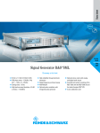
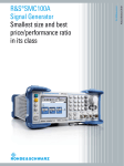
Titel.indd 1 Data Sheet | 01.00 Test & Measurement R&S®FSV Signal Analyzer Specifications 12.06.2008 17:54:00 CONTENTS Specifications.................................................................................................................................................................. 3 Frequency ...............................................................................................................................................................................................3 Sweep time .............................................................................................................................................................................................4 Resolution bandwidths............................................................................................................................................................................4 Level .......................................................................................................................................................................................................5 Measurement speed ...............................................................................................................................................................................7 Trigger functions .....................................................................................................................................................................................8 I/Q data ...................................................................................................................................................................................................8 Inputs and outputs ..................................................................................................................................................................................9 General data .........................................................................................................................................................................................10 Options .......................................................................................................................................................................... 11 ® R&S FSV-B3 audio demodulator..........................................................................................................................................................11 ® R&S FSV-B5 additional interfaces .......................................................................................................................................................11 Ordering information .................................................................................................................................................... 12 Options..................................................................................................................................................................................................12 Recommended extras ...........................................................................................................................................................................13 ® Power sensors supported by R&S FSV-K9 option ...............................................................................................................................13 2 ® R&S FSV Signal Analyzer Version 01.00, June 2008 Specifications Specifications apply under the following conditions: 30 minutes warm-up time at ambient temperature, specified environmental conditions met, calibration cycle adhered to, and all internal automatic adjustments performed. Data without tolerances: typical values only. Data designated "nominal" applies to design parameters and is not tested. Rohde & Schwarz equipment is designed for reliable operation up to an altitude of 3000 m above sea level, and for transport up to an altitude of 4500 m above sea level. Frequency Frequency range ® R&S FSV 3 DC coupled AC coupled ® R&S FSV 7 DC coupled AC coupled ® with R&S FSV-B29 option, DC coupled Frequency resolution Reference frequency, internal Accuracy Aging per year Temperature drift (+5 °C to +45 °C) Max. initial calibration accuracy standard ® with R&S FSV-B4 OCXO reference frequency option standard ® with R&S FSV-B4 OCXO reference frequency option standard ® with R&S FSV-B4 OCXO reference frequency option Frequency readout Marker resolution Uncertainty Number of sweep (trace) points Marker tuning frequency step size default value range marker step size = sweep points marker step size = standard Frequency counter resolution Count accuracy Display range for frequency axis Resolution Max. span deviation Spectral purity SSB phase noise Residual FM Version 01.00, June 2008 frequency = 500 MHz, carrier offset 100 Hz 1 kHz 10 kHz 100 kHz 1 MHz 10 MHz frequency = 500 MHz, RBW = 1 kHz, sweep time = 100 ms 9 kHz to 3.6 GHz 1 MHz to 3.6 GHz 9 kHz to 7 GHz 1 MHz to 7 GHz 20 Hz to fmax 0.01 Hz (time since last adjustment × aging rate) + temperature drift + calibration accuracy –6 1 × 10 –7 1 × 10 –6 1 × 10 –7 1 × 10 –7 5 × 10 –8 5 × 10 1 Hz ±(marker frequency × reference uncertainty + 10 % × resolution bandwidth + ½ (span / (sweep points –1)) + 1Hz) 691 101 to 32001 span / (sweep points – 1) span / (default sweep points – 1) 0.001 Hz ±(frequency × reference uncertainty + ½ (last digit)) 0 Hz, 10 Hz to max. frequency 0.1 Hz 0.1 % <–84 dBc (1 Hz) <–101 dBc (1 Hz) <–106 dBc (1 Hz) <–115 dBc (1 Hz) <–134 dBc (1 Hz) typ. –150 dBc (1 Hz) <3 Hz, nominal ® R&S FSV Signal Analyzer 3 -60 -70 -80 SSB phase noise (dBc(1Hz)) center frequency < 20 MHz -90 center frequency 200 MHz -100 center frequency 500 MHz -110 center frequency 1 GHz -120 center frequency 3 GHz -130 center frequency 6 GHz -140 -150 -160 100 Hz 1 kHz 10 kHz 100 kHz 1 MHz 10 MHz Typical phase noise at different center frequencies Sweep time Range span = 0 Hz span ≥ 10 Hz, swept span ≥ 10 Hz, FFT span = 0 Hz span ≥ 10 Hz, swept 1 µs to 16000 s 1 1 ms to 16000 s 2 7 μs to 16000 s 0.1%, nominal 3 %, nominal span ≥ 10 Hz, sweep filters span ≥ 10 Hz, FFT filters span = 0 Hz ® with R&S FSV-B70 option, span = 0 Hz 1 Hz to 10 MHz in 1/2/3/5 sequence 1 Hz to 300 kHz in 1/2/3/5 sequence 20 MHz, 28 MHz additionally 40 MHz additionally <3%, nominal <5, nominal standard (RRC = root raised cosine) Bandwidth accuracy Shape factor 60 dB:3 dB 100 Hz, 200 Hz, 300 Hz, 500 Hz 1, 1.5, 2, 2.4, 2.7, 3, 3.4, 4, 4.5, 5, 6, 8.5, 9, 10, 12.5, 14, 15, 16, 18 (RRC), 20, 21, 24.3 (RRC), 25, 30, 50, 100, 150, 192, 200, 300, 500 kHz 1, 1.228, 1.28 (RRC), 1.5, 2, 3, 3.84 (RRC), 4.096 (RRC), 5, ,10, 20, 28 MHz 40 MHz additionally <2 %, nominal <2, nominal EMI filters Bandwidths (–6 dB) Bandwidth uncertainty Shape factor 60 dB:3 dB 200 Hz, 9 kHz, 120 kHz, 1 MHz <3 %, nominal <6, nominal Sweep time accuracy Resolution bandwidths Sweep filters and FFT filters Resolution bandwidths (–3 dB) Bandwidth uncertainty Shape factor 60 dB:3 dB Channel filters Bandwidths (–3 dB) ® with R&S FSV-B70 option 1 Net sweep time without additional hardware settling time. 2 Time for data acquisition for FFT calculation. 4 R&S FSV Signal Analyzer ® Version 01.00, June 2008 Video bandwidths with R&S FSV-B70 option 1 Hz to 10 MHz in 1/2/3/5 sequence, 20 MHz, 28 MHz 40 MHz additionally standard ® with R&S FSV-B70 option 28 MHz, nominal 40 MHz, nominal ® Signal analysis bandwidth Level Display range Maximum input level DC voltage CW RF power Pulse spectral density Max. pulse voltage Max. pulse energy Intermodulation 1 dB compression of input mixer Third-order intercept point (TOI) Second harmonic intercept (SHI) Version 01.00, June 2008 displayed noise floor up to +30 dBm AC coupled DC coupled RF attenuation 0 dB RF preamplifier = OFF ® with R&S FSV-B22 option, RF preamplifier = ON RF attenuation ≥10 dB RF preamplifier = OFF ® with R&S FSV-B22 option, RF preamplifier = ON RF attenuation 0 dB, RF preamplifier = OFF RF attenuation ≥ 10 dB RF attenuation ≥ 10 dB, 10 µs 50 V 0V 20 dBm (= 0.1 W) 13 dBm (= 0.02 W) 30 dBm (= 1 W) 23 dBm (= 0.2 W) 97 dB µV/MHz 150 V 1 mWs RF attenuation 0 dB RF preamplifier = OFF +3 dBm, nominal ® with R&S FSV-B22 option, –12 dBm, nominal RF preamplifier = ON level 2 × –10 dBm, ∆f > 5 × RBW or 10 kHz, whichever is larger, RF preamplifier = OFF 10 MHz ≤ fin < 100 MHz >12 dBm, typ. 15 dBm 300 MHz ≤ fin < 3.6 GHz >13 dBm, typ. 16 dBm 3.6 GHz ≤ fin ≤ 7 GHz >15 dBm, typ. 18 dBm ® with R&S FSV-B22 option, RF preamplifier = ON, level 2 × –10 dBm, ∆f > 5 × RBW or 10 kHz, whichever is larger 10 MHz ≤ fin < 100 MHz –3 dBm, nominal 300 MHz ≤ fin < 3.6 GHz –2 dBm, nominal 3.6 GHz ≤ fin ≤ 7 GHz 0 dBm, nominal 100 MHz < fin ≤ 3.5 GHz RF preamplifier = OFF typ. 40 dBm ® with R&S FSV-B22 option, 25 dBm, nominal RF preamplifier = ON ® R&S FSV Signal Analyzer 5 Displayed average noise level 0 dB RF attenuation, termination 50 Ω, log. scaling, normalized to 1 Hz RBW, RBW = 1 kHz, VBW = 3 kHz, zero span, sweep time 50 ms, sample detector, trace average, sweep count = 20, mean marker, RF preamplifier = OFF 9 kHz ≤ f < 100 kHz <–130 dBm, typ. –140 dBm 100 kHz ≤ f < 1 MHz <–145 dBm, typ. –150 dBm 1 MHz ≤ f < 1 GHz <–152 dBm, typ. –155 dBm 1 GHz ≤ f < 3.6 GHz <–150 dBm, typ. –153 dBm 3.6 GHz ≤ f < 6 GHz <–148 dBm, typ. –151 dBm 6 GHz ≤ f ≤ 7 GHz <–146 dBm, typ. –149 dBm ® with R&S FSV-B22 option, RF preamplifier = ON 0 dB RF attenuation, termination 50 Ω, log. scaling, normalized to 1 Hz RBW, RBW = 1 kHz, VBW = 3 kHz, zero span, sweep time 50 ms, sample detector, trace average, sweep count = 20, mean marker 100 kHz ≤ f < 1 MHz <–150 dBm, typ. –155 dBm 1 MHz ≤ f < 1 GHz <–162 dBm, typ. –165 dBm 1 GHz ≤ f < 3.6 GHz <–160 dBm, typ. –163 dBm 3.6 GHz ≤ f < 6 GHz <–158 dBm, typ. –161 dBm 6 GHz ≤ f ≤ 7 GHz <–156 dBm, typ. –159 dBm ® with R&S FSV-B29 option, RF preamplifier = OFF 0 dB RF attenuation, termination 50 Ω, log. scaling, normalized to 1 Hz RBW, RBW = 5 Hz, VBW = 5 Hz, zero span, sweep time 500 ms, sample detector, trace average, sweep count = 20, mean marker 20 Hz <–100 dBm, typ. –110 dBm 100 Hz <–110 dBm, typ. –120 dBm 1 kHz <–120 dBm, typ. –130 dBm Spurious responses Image response Intermediate frequency response Residual spurious response Local oscillator related spurious Other interfering signals Subharmonic of 1st LO Harmonic of 1st LO fin – 2 × 8410 MHz (1st IF) fin – 2 × 730 MHz (2nd IF) fin – 2 × 90 MHz (3rd IF) 1st IF (8410 MHz) 2nd IF (730 MHz) 3rd IF (90 MHz) 0 dB RF attenuation f ≤ 1 MHz f > 1 MHz 1 kHz ≤ offset from carrier ≤ 10 MHz offset from carrier > 10 MHz spurious at 8410 MHz – 2 × fin mixer level <–25 dBm, spurious at fin – 4205 MHz Level display Logarithmic level axis Linear level axis Number of traces Trace detector EMI detectors Trace functions Setting range of reference level Units of level axis 6 ® R&S FSV Signal Analyzer logarithmic level display linear level display typ.<–80 dBc <–80 dBc <–80 dBc typ.<–70 dBc <–80 dBc <–80 dBc <–90 dBm <–103 dBm <–70 dBc <–80 dBc <–70 dBc <–70 dBc 1 dB to 200 dB, in steps of 1/2/5 10 % of reference level per level division, 10 divisions or logarithmic scaling 6 Max Peak, Min Peak, Auto Peak (Normal), Sample, RMS, Average Quasi Peak Clear/Write, Max Hold, Min Hold, Average, View –130 dBm to (–10 dBm + RF attenuation –RF preamplifier gain), in steps of 0.01 dB dBm, dBµV, dBmV, dBµA, dBpW µV, mV, µA, mA, pW, nW Version 01.00, June 2008 Level measurement uncertainty Absolute level uncertainty at 64 MHz Frequency response referenced to 64 MHz Attenuator switching uncertainty Uncertainty of reference level setting Bandwidth switching uncertainty Display nonlinearity Logarithmic level display Linear level display RBW = 10 kHz, level –10 dBm, reference level –10 dBm, RF attenuation 10 dB +20 °C to +30 °C <0.2 dB (σ = 0.07 dB) +5 °C to +40 °C <0.35 dB (σ = 0.12 dB) DC coupling, RF attenuation 10 dB, 20 dB,30 dB ,40 dB, RF preamplifier = OFF, +20 °C to +30 °C 9 kHz ≤ f < 10 MHz <0.5 dB (σ = 0.17 dB) 10 MHz ≤ f < 3.6 GHz <0.3 dB (σ = 0.1 dB) 3.6 GHz ≤ f < 7 GHz <0.5 dB (σ = 0.17 dB) any setting of RF attenuation or RF preamplifier, +5 °C to +40 °C 9 kHz ≤ f < 3.6 GHz <1 dB (σ = 0.33 dB) 3.6 GHz ≤ f ≤ 7 GHz <1.5 dB (σ = 0.5 dB) ® with R&S FSV-B29 option, DC coupling, RF preamplifier = OFF, +5 °C to +40 °C 20 Hz ≤ f < 9 kHz <1 dB (σ = 0.33 dB) f = 64 MHz, 0 dB to 70 dB, <0.2 dB (σ = 0.07 dB) referenced to 10 dB attenuation 3 0 dB referenced to RBW = 10 kHz sweep filters <0.1 dB (σ = 0.04 dB) FFT filters <0.2 dB (σ = 0.07 dB) S/N > 16 dB, 0 dB to –70 dB S/N > 16 dB, 0 dB to –70 dB <0.1 dB (σ = 0.04 dB) 5 % of reference level Total measurement uncertainty signal level 0 dB to –70 dB below reference level, S/N >20 dB, sweep time auto, sweep type = sweep, RF attenuation 10 dB, 20 dB, 30 dB, 40 dB, RF preamplifier = OFF, span/RBW <100, 95 % confidence level, +20 °C to +30 °C 9 kHz ≤ f < 10 MHz 0.39 dB 10 MHz ≤ f < 3.6 GHz 0.28 dB 3.6 GHz ≤ f < 7 GHz 0.39 dB Measurement speed Local measurement and display update rate Remote measurement 1000 sweep averages Remote measurement and LAN transfer Marker peak search Center frequency tune and transfer 3 2 ms (500/s) 1 ms (1000/s) 3 ms (333/s) 1.5 ms 15 ms The setting of the reference level affects only the graphical representation of the measurement result on the display, not the measurement itself. Therefore the reference level setting causes no additional uncertainty in measurement results. Version 01.00, June 2008 ® R&S FSV Signal Analyzer 7 Trigger functions Trigger Trigger source Trigger offset span ≥ 10 Hz span = 0 Hz Max. deviation of trigger offset IF power trigger Sensitivity minimum signal power maximum signal power IF power trigger bandwidth RBW > 500 kHz, swept RBW > 20 kHz, FFT RBW ≤ 500 kHz, swept RBW ≤ 20 kHz, FFT Gated sweep Gate source Gate delay free run, video, external, IF power 31.25 ns to 30 s, resolution 31.25 ns min. (or 1 % of offset) sweep time to 30 s, resolution 31.25 ns min. (or 1 % of offset) ±(7.8125 ns + (0.1 % × trigger offset)) –60 dBm + RF attenuation – RF preamplifier gain –10 dBm + RF attenuation – RF preamplifier gain 40 MHz, nominal 6 MHz, nominal video, external, IF power 31.25 ns to 30 s, min. resolution 31.25 ns (or 1 % of delay) 31.25 ns to 30 s, min. resolution 31.25 ns (or 1 % of gate length) ±(7.8125 ns + (0.1 % × gate length)) Gate length Max. deviation of gate length I/Q data Interface Memory length Word length of I/Q samples Sample rate Max. signal bandwidth (equalized) Amplitude flatness Deviation from linear phase 8 ® R&S FSV Signal Analyzer sampling rate > 64 MHz or number of samples > 100 Msample otherwise standard ® with R&S FSV-B70 option standard ® with R&S FSV-B70 option GPIB or LAN interface max. 200 Msamples I and Q 18 bit 24 bit 100 Hz to 45 MHz 100 Hz to 128 MHz 28 MHz 40 MHz 0.3 dB, nominal 1°, nominal Version 01.00, June 2008 Inputs and outputs RF input Impedance Connector VSWR Setting range of attenuator RF preamplifier gain 50 Ω N female RF attenuation ≥10 dB 10 MHz ≤ f < 3.6 GHz 3.6 GHz ≤ f ≤ 7 GHz RF attenuation <10 dB, DC coupled 10 MHz ≤ f ≤ 7 GHz standard ® with R&S FSV-B25 option ® with R&S FSV-B22 option Probe power supply Supply voltages typ. 2 0 dB to 75 dB, in 5 dB steps 0 dB to 75 dB, in 1 dB steps 20 dB, nominal +15 V DC, –12.6 V DC and ground, max. 150 mA, nominal Noise source drive Connector Output voltage BNC female 0 V/28 V, max.100 mA, switchable, nominal Power sensor Connector 6-pin LEMOSA female for supported ® R&S NRP-Zxx power sensors USB interface Reference output Connector Impedance Output frequency <1.5 <2 2 ports, type A plug, version 2.0 Level BNC female 50 Ω 10 MHz same as reference input signal >0 dBm, nominal Reference input Connector Impedance Input frequency range Required level BNC female 50 Ω 1 MHz ≤ fin ≤ 20 MHz, in 1 MHz steps >0 dBm from 50 Ω External trigger/gate input Connector Trigger voltage Input impedance BNC female 0.5 V to 3.5 V 10 kΩ IEC/IEEE bus control Command set Connector Interface functions External monitor Connector Version 01.00, June 2008 internal reference external reference interface in line with IEC 625-2 (IEEE 488.2) SCPI 1997.0 24-pin Amphenol female SH1, AH1, T6, L4, SR1, RL1, PP1, DC1, DT1, C0 VGA-compatible, 15-pin, mini D-Sub ® R&S FSV Signal Analyzer 9 General data Data storage Internal External Temperature Temperature hard disk ≥ 40 Gbyte, nominal supports USB 2.0-compatible memory devices operating temperature range permissible temperature range storage temperature range +5 °C to +40 °C 0°C to +50°C –40 °C to +70 °C +40 °C at 90 % rel. humidity, in line with EN 60068-2-30 sinusoidal 5 Hz to 150 Hz, max. 2 g at 55 Hz; 0.5 g from 55 Hz to 150 Hz; in line with EN 60068-2-6 EN 60068-2-64 10 Hz to 130 Hz, acceleration 1.2 g (rms) 40 g shock spectrum, in line with MIL-T-28800F, classes 3 and 5 Climatic loading Mechanical resistance Vibration random Shock EMC EMC Directive 2004/108/EC including: EN 61326 class B (emission), 4 CISPR 11/EN 55011/ group 1 class A (emission) EN 61326 table A.1 (immunity, industrial) Recommended calibration interval 1 year Power supply AC supply 100 V to 240 V, 3 A to 1.25 A; 50 Hz to 400 Hz, class of protection I to VDE 411 typ. 90 W, max. 175 W with all options in line with EN 61010-1, UL 3111-1, CSA C22.2 No. 1010-1, IEC 1010-1 VDE, GS, CSA, CSA-NRTL Power consumption Safety Test mark Weight and dimensions Dimensions W×H×D Net weight without options, nominal R&S FSV3, R&S FSV7 ® ® 412 mm × 197 mm × 417 mm 16.22 in × 7.76 in × 16.42 in 9.5 kg 20.94 lb 4 Note regarding use of instrument: The instrument complies with the emission requirements stipulated by EN 55011 class A. This means that the instrument is suitable for use in industrial environments. According to EN 61000-6-4, operation is not covered in residential, commercial, and business areas nor in small-size companies. Thus the instrument must not be operated in residential, commercial, and business areas nor in small-size companies, unless additional measures are taken to ensure that EN 61000-6-3 is met. 10 ® R&S FSV Signal Analyzer Version 01.00, June 2008 Options R&S®FSV-B3 audio demodulator Demodulation AF demodulation types Audio output Marker stop time in spectrum mode AF output Connector Output impedance Open-circuit voltage AM and FM loudspeaker and phone jack 100 ms to 60 s 3.5 mm mini jack 10 Ω up to 1.5 V, adjustable R&S®FSV-B5 additional interfaces User port Connector Output Input IF/video/demod out Connector IF out Bandwidth IF frequency Output level (gain versus RF input) Video out Bandwidth Output scaling Output level 9-pin D-Sub male TTL-compatible, 0 V/5 V max. 15 mA TTL-compatible, max. 5 V BNC female, 50 Ω RF attenuation 0 dB, RF preamplifier OFF, span 0 Hz display scale log display scale lin center frequency > 10 MHz, span 0 Hz, signal at reference level and center frequency equal to RBW setting 32 MHz 0 dB, nominal equal to VBW setting log. scaling lin. scaling 1 V, open circuit, nominal Trigger out Connector Output BNC female TTL-compatible, 0 V/5 V USB interface 2 ports, type A plug, version 2.0 Version 01.00, June 2008 ® R&S FSV Signal Analyzer 11 Ordering information Designation Type Order No. ® Signal Analyzer R&S FSV3 1307.9002.03 ® Signal Analyzer R&S FSV7 1307.9002.07 Accessories supplied Power cable, quick start guide and CD-ROM (with operating manual and service manual) Options Designation Ruggedized Housing Audio Demodulator OCXO Reference Frequency Additional Interfaces Type ® R&S FSV-B1 ® R&S FSV-B3 ® R&S FSV-B4 ® R&S FSV-B5 Spare Hard drive RF Preamplifier (9 kHz to 7 GHz) Electronic Attenuator, 1 dB steps Frequency Range Extension 20 Hz 40 MHz Analysis Bandwidth Firmware/software Analog Modulation Analysis (AM/FM/φM) Power Sensor Support R&S FSV-B19 ® R&S FSV-B22 ® R&S FSV-B25 ® R&S FSV-B29 ® R&S FSV-B70 GSM/EDGE Analysis 3GPP FDD BS Analysis 3GPP FDD UE Analysis WLAN IEEE 802.11a/b/g/j Analysis WLAN IEEE 802.11n Analysis WiMAX IEEE 802.16 OFDM/OFDMA Analysis EUTRA/LTE BS Analysis EUTRA/LTE UE Analysis R&S FSV-K10 ® R&S FSV-K72 ® R&S FSV-K73 ® R&S FSV-K91 ® R&S FSV-K91n ® R&S FSV-K93 12 ® R&S FSV Signal Analyzer Order No. 1310.9500.02 1310.9516.02 1310.9522.02 1310.9539.02 Retrofittable no yes yes yes ® 1310.9574.02 1310.9600.02 1310.9622.02 1310.9639.02 1310.9645.02 yes yes yes yes yes ® 1310.8103.02 1310.8203.02 R&S FSV-K7 ® R&S FSV-K9 ® ® R&S FSV-K100 ® R&S FSV-K101 1310.8055.02 1310.8503.02 1310.8555.02 1310.8903.02 1310.9468.02 1310.9416.02 Remarks retrofit in service center user- retrofittable IF out, video out, AUX port, trigger out, 2 × USB user- retrofittable user- retrofittable user- retrofittable retrofit in service center user- retrofittable ® supports R&S NRP power sensors ® requires R&S FSV-B70 1310.9051.02 1310.9100.02 Version 01.00, June 2008 Recommended extras Designation Headphones IEC/IEEE Bus Cable, 1 m IEC/IEEE Bus Cable, 2 m ® 19” Rack Adapter (not for R&S FSV-B1) Soft Carrying Case (grey) Matching pads, 50/75 Ω L Section, matching at both ends Series Resistor, 25 Ω, matching at one end (taken into account in instrument function RF INPUT 75 Ω) SWR bridges, 50 Ω SWR Bridge, 5 MHz to 3 GHz SWR Bridge, 40 kHz to 4 GHz High-power attenuators 100 W, 3/6/10/20/30 dB, 1 GHz Type ® R&S PCK ® R&S PCK ® R&S ZZA-478 ® R&S ZZT-473 Order No. 0708.9010.00 0292.2013.10 0292.2013.20 1096.3248.00 1109.5048.00 R&S RAM ® R&S RAZ ® 0358.5414.02 0358.5714.02 ® 0373.9017.5X 1039.9492.5X ® 1073.8495.XX (XX = 03/06/10/20/30) 1073.8695.XX (XX = 03/06/10/20/30) 1035.1700.52 R&S ZRB2 ® R&S ZRC R&S RBU100 ® 50 W, 3/6/10/20/30 dB, 2 GHz R&S RBU50 50 W, 20 dB, 6 GHz Connectors and cables Probe power connector, 3-pin DC blocks DC Block, 10 kHz to 18 GHz (type N) R&S RDL50 ® 1065.9480.00 ® R&S FSE-Z4 1084.7443.02 Power sensors supported by R&S®FSV-K9 option Order designation Average Power Sensor 10 MHz to 8 GHz, 200 mW Average Power Sensor 10 MHz to 18 GHz, 200 mW Average Power Sensor 10 MHz to 18 GHz, 2 W Average Power Sensor 10 MHz to 18 GHz, 15 W Average Power Sensor 10 MHz to 18 GHz, 30 W Power Sensor Module with Power Splitter DC to 18 GHz, 500 mW Power Sensor Module with Power Splitter DC to 26.5 GHz, 500 mW Average Power Sensor 9 kHz to 6 GHz, 200 mW Thermal Power Sensor 0 Hz to 18 GHz, 100 mW Thermal Power Sensor 0 Hz to 40 GHz, 100 mW Wideband Power Sensor 50 MHz to 18 GHz, 100 mW Version 01.00, June 2008 Type ® R&S NRP-Z11 Order No. 1138.3004.02 ® 1137.6000.02 ® 1137.7506.02 ® 1137.8002.02 ® 1137.8502.02 ® 1169.4102.02 ® 1169.3206.02 ® 1168.8004.02 ® 1138.0005.02 ® 1138.2008.02 ® 1137.9009.02 R&S NRP-Z21 R&S NRP-Z22 R&S NRP-Z23 R&S NRP-Z24 R&S NRP-Z27 R&S NRP-Z37 R&S NRP-Z91 R&S NRP-Z51 R&S NRP-Z55 R&S NRP-Z81 ® R&S FSV Signal Analyzer 13 Service you can rely on J In 70 countries J Person-to-person J Customized and flexible with a warranty J No hidden terms J Quality About Rohde & Schwarz Rohde & Schwarz is an independent group of companies specializing in electronics. It is a leading supplier of solutions in the fields of test and measurement, broadcasting, radiomonitoring and radiolocation, as well as secure communications. Established 75 years ago, Rohde & Schwarz has a global presence and a dedicated service network in over 70 countries. Company headquarters are in Munich, Germany. Regional contact Europe, Africa, Middle East +49 1805 12 42 42* or +49 89 4129 137 74 [email protected] North America 1-888-TEST-RSA (1-888-837-8772) [email protected] Latin America +1-410-910-7988 [email protected] Asia/Pacific +65 65 13 04 88 [email protected] Certified Quality System Certified Environmental System DQS REG. NO 1954 QM DQS REG. NO 1954 UM ISO 9001 ISO 14001 For product brochure, see PD 5214.0499.12 and www.rohde-schwarz.com (search term: FSV) Rohde & Schwarz GmbH & Co. KG Mühldorfstraße 15 | 81671 München Phone +49 89 41 290 | Fax +49 89 41 29 121 64 www.rohde-schwarz.com R&S® is a registered trademark of Rohde & Schwarz GmbH & Co. KG Trade names are trademarks of the owners | Printed in Germany (as) PD 5214.0499.22 | Version 01.00 | June 2008 | R&S®FSV Data without tolerance limits is not binding | Subject to change *0.14 €/min within German wireline network; rates may vary in other networks (wireline and mobile) and countries. Titel.indd 2 26.06.2008 14:34:22