1
About this Manual
We’ve added this manual to the Agilent website in an effort to help you support
your product. This manual is the best copy we could find; it may be incomplete
or contain dated information. If we find a more recent copy in the future, we will
add it to the Agilent website.
Support for Your Product
Agilent no longer sells or supports this product. Our service centers may be able
to perform calibration if no repair parts are needed, but no other support from
Agilent is available. You will find any other available product information on the
Agilent Test & Measurement website, www.tm.agilent.com.
HP References in this Manual
This manual may contain references to HP or Hewlett-Packard. Please note that
Hewlett-Packard's former test and measurement, semiconductor products and
chemical analysis businesses are now part of Agilent Technologies. We have
made no changes to this manual copy. In other documentation, to reduce
potential confusion, the only change to product numbers and names has been in
the company name prefix: where a product number/name was HP XXXX the
current name/number is now Agilent XXXX. For example, model number
HP8648A is now model number Agilent 8648A.
HP 11807E, Option 014
AMPS/NAMPS/DAMPS/DCCH Mobile Test Software
User’s Guide
Software Version B.02.00 and above
HP Part No. 11807-90145
Printed in U. S. A.
August 1997
Rev B
1
Copyright © Hewlett-Packard Company 1996, 1997
RESTRICTED
Use, duplication or disclosure by the U.S. Government is subject to restrictions as
RIGHTS LEGEND set forth in subparagraph (c) (1) (ii) of the Rights in Technical Data and Computer
Software clause in DFARS 252.227-7013.
Hewlett-Packard Company
3000 Hanover Street
Palo Alto, CA 94304 U.S.A.
Rights for non-DOD U.S. Government Departments and Agencies are as set forth
in FAR 52.227-19 (c) (1,2).
2
Organization of
this Manual
This manual describes the set up and use of the HP 11807E, Option 014, AMPS/
NAMPS/DAMPS/DCCH Mobile Test Software with the HP 8920B RF
Communications Test Set. The manual is arranged in chapters as follows:
Chapter 1 - Getting Started
Provides procedures for connecting the equipment for a typical application,
turning on the equipment, loading the software, connecting the equipment for
testing, and running a set of basic performance tests.
Chapter 2 - Product Description
Provides general and detailed descriptions of the Test Software; a description of
associated hardware considerations; descriptions of all connectors, keys, and
knobs; and detailed descriptions of the Test Software display screens.
Chapter 3 - Using the Test Software
Provides descriptions of and procedures for using the features and functions of the
Test Software in a typical application, and procedures for customizing the Test
Software for a particular application.
Chapter 4 - Operation Descriptions
Provides descriptions of all setup and test operations that can be performed on
cellular telephones using the Test Software.
Chapter 5 - Problem Solving
Provides information on solving common problems.
Chapter 6 - Reference
Provides descriptions and procedures for performing the less common or more
sophisticated functions of the Test Software.
Glossary
Provides definitions for unusual and special terms used in the Test Software and in
this manual.
Index
Provides a listing of topics and the location of information about these topics in this
manual.
3
Conventions
Special presentations of text in this manual reflect the appearance of the referenced
item. Examples are:
TESTS
A key on the Test Set front panel.
Procedure:
Characters shown on the Test Set display.
k1 (Run Test)
A USER key in the key column next to the Test Set display. (The words Run
Test are shown on the Test Set display.)
0.000000
A field on the Test Set display in which entries may be made.
Titles of documentation and references to other sections of this user’s guide are
printed in italics.
The term Test Set refers to the HP 8920B RF Communications Test Set.
The term Test System refers to the HP 8920B RF Communications Test Set, the
HP 83206 TDMA Cellular Adapter, the HP 11807E, Option 014, AMPS/NAMPS/
DAMPS/DCCH Mobile Test Software, and any ancillary equipment required for
testing.
The term Test Software refers to the HP 11807E, Option 014, AMPS/NAMPS/
DAMPS/DCCH Mobile Test Software.
The term Operation refers to any of the primary testing functions of the Test
Software.
In the steps in this manual the following words are used to describe cursor and
entry actions:
4
•
select refers to positioning the cursor to the left of the desired field (inverse video
area), then pressing the cursor control knob.
•
enter means to use the numeric keypad and the ENTER key or measurement units keys
to make entries to fields. In some procedures, enter is used to describe the action of
entering characters into a field.
Additional Services Consult the HP 8920B Users Guide or call the HP 8920 Hotline 1-800-922-8920
(In USA and Canada only) and give your software model number.
Available
Contact your local HP Sales Representative for information about the Software
Upgrade Service and the Start Up Assistance Training Course.
5
6
Table of Contents
Contents
1 Getting Started
What You Will Test 20
Making Connections 23
Setup and Software Card Loading 24
Selecting and Running the Initial Tests 26
7
Contents
2 Product Description
Test Software 30
Hardware Considerations 32
Tests Subsystem 41
8
Contents
3 Using the Software
Introduction 66
Connecting Equipment 67
Calibrating Cable Loss 72
Testing Overview 73
Using Common Processes 79
Customizing Testing 94
9
Contents
4 Operation Descriptions
Introduction 102
Testing Strategy 104
GEN Modify Execution Parameters 110
GEN Modify External Power Supply Parameters 113
GEN Modify Analog Control Channel Parameters 115
GEN Modify Digital Control Channel Parameters 116
CP Registration on Analog Control Channel 118
CP Registration on Digital Control Channel 120
CP Page from Analog Control Channel to Analog Voice
Channel 122
CP Page from Analog Control Channel to Narrow Analog Voice
Channel 125
CP Page from Analog Control Channel to Digital Traffic
Channel 128
CP Page from Digital Control Channel to Analog Voice
Channel 131
CP Page from Digital Control Channel to Digital Traffic
Channel 135
CP Origination from Analog Control Channel to Analog Voice
Channel 138
CP Origination from Analog Control Channel to Narrow Analog
Voice Channel 140
10
Contents
CP Origination from Analog Control Channel to Digital Traffic
Channel 142
CP Origination from Digital Control Channel to Analog Voice
Channel 144
CP Origination from Digital Control Channel to Digital Traffic
Channel 146
CP Handoff from Analog Voice Channel to Analog Voice
Channel 148
CP Handoff from Analog Voice Channel to Narrow Analog Voice
Channel 150
CP Handoff from Analog Voice Channel to Digital Traffic
Channel 152
CP Handoff from Narrow Analog Voice Channel to Analog Voice
Channel 154
CP Handoff from Narrow Analog Voice Channel to Narrow Analog
Voice Channel 156
CP Handoff from Digital Traffic Channel to Digital Traffic
Channel 158
CP Handoff from Digital Traffic Channel to Analog Voice
Channel 160
CP Release to Analog Control Channel 162
CP Release to Digital Control Channel 164
CP Hook Flash 167
TXA Audio Distortion 168
TXA Audio Frequency Response 170
11
Contents
TXA Compressor Response 173
TXA Current Drain 177
TXA Digital Signaling Tone Deviation and Code 182
TXA Dual-Tone-Multiple-Frequency Key Pad and
Dual-Tone-Multiple-Frequency Frequency Error 184
TXA Digital Supervisory Audio Tone Deviation, Closure, and
Phase Jitter 186
TXA FM Hum and Noise 191
TXA Frequency Error 193
TXA Modulation Deviation Limiting on Analog Voice
Channel 194
TXA Modulation Deviation Limiting on Narrow Analog Voice
Channel 197
TXA RF Power Output 200
TXA RF Power Output vs Channel (Plotted) 204
TXA Signaling Tone Frequency and Deviation 209
TXA Supervisory Audio Tone Frequency Error and Deviation 211
TXA Wideband Data Deviation 214
RXA Audio Distortion 218
RXA Audio Frequency Response 220
RXA Expandor 224
RXA Forward Voice Channel Order Message Error Rate 229
12
Contents
RXA Hum and Noise 231
RXA Mobile Reported Interference 233
RXA RF Sensitivity 235
RXA RF Sensitivity, Narrow Analog Voice Channel 238
RXA RF Sensitivity vs Channel (Plotted) 241
TXD Adjacent Channel Power 245
TXD Modulation Accuracy 247
TXD Modulation Accuracy (10 Burst) 253
TXD RF Power Output 259
TXD RF Power Output vs Channel (Plotted) 264
TXD Time Alignment 270
RXD Receiver Sensitivity 272
RXD Receiver Sensitivity (Loopback) 274
MISC Battery Life on Analog Voice Channel, Transmit 276
MISC Battery Life on Digital Traffic Channel, Transmit 278
MISC Battery Life on Analog Control Channel, Standby 280
MISC Battery Life on Digital Control Channel, Standby 282
MISC Digital Talk Back 284
MISC TX Qualitative Audio 285
MISC RX Qualitative Audio 286
13
Contents
5 Problem Solving
Introduction 288
Data Collection Function Does Not Work 289
Memory Space Problems 291
Printing Problems 292
Test Results Are Unexpected 293
Test Set Doesn’t Power Up 294
Error Messages 295
14
Contents
6 Reference
Introduction 304
Copying Files 305
Data Collection and Retrieval 307
Memory Cards 321
Printing 327
RAM Disk 335
Saving Tests Results 338
Serial Port 339
Understanding HP-IB Control Annunciators 341
USER Keys 342
15
Contents
Glossary 345
16
Contents
Index 357
17
Contents
18
1
Getting Started
Getting Started
19
Chapter 1, Getting Started
What You Will Test
What You Will Test
Getting Started will acquaint you quickly with the operation of the Test Set and
the Test Software. You will do the following:
1.
2.
3.
4.
5.
Register a cellular telephone.
Test the transmitter frequency error.
Test the transmitter wideband data deviation.
Test the transmitter power on power levels 2-7.
Release the cellular telephone to an analog control channel.
These Operations will do the following:
Establish that the Test Software has been loaded properly.
Verify that the Test Set and the Test Software function together properly as a
Test System.
Verify that the Test System functions with the cellular telephone.
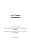
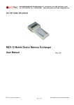
Test System Components
The Test System includes the following components:
•
HP 8920B, Option 800, RF Communications Test Set, which consists of the following:
HP 8920B RF Communications Test Set
HP 83206 TDMA Cellular Adapter
•
HP 11807E, Option 014 , AMPS/NAMPS/DAMPS/DCCH Mobile Test Software
These components are shown in figure 1 .
20
Chapter 1, Getting Started
What You Will Test
Instrument Display
Screen
USER Keys
Use to enter some
commands quickly
RF IN/OUT
TO
TEST SET
PRESET Key
Use to reset all
instrument settings
Getting Started
HP 83206 TDMA
Cellular Adapter
TESTS Key
Use to access the
main Tests screen
832 06A
T DM A / C D P D C E L LU LA R A D A P T E R
PWR
REF
UNLOCK
RF IN/OUT
MAX.PWR 60W
CONTINUOUS
ANALYZER
ANALYZER
ANALYZER
GENERAT OR
DATA
CLOCK IN
BASEBAND
DATA IN
TRIGGER
IN
BASEBAND
DATA IN
HP 8920B RF
Communications
Test Set
POWER Switch
Shift and Cancel Keys
Use to abort
IBASIC programs
Cursor Control Knob
Use to position cursor
and make screen
selections
HP 11807E
Option 014 Test
Software
Insertion End
(H (H
Data Keys
Use to enter
specifications and
parameter values, and
so forth
UP
AMPS/NAMPS/DAMPS/DCCH
Mobile Test Software
For use in the HP 8920B RF Communications
Test Set
Insert Card
Press TESTS
Select “Card” for Procedure Location
Select desired Procedure Filename
Select “Run Test”
Hewlett-Packard Company 1992-1996 / All Rights Reserved / Made in USA
P/N 11807-90145
HP 11807E Option 014 / Rev. B.02.00
Figure 1
Test System
21
Chapter 1, Getting Started
What You Will Test
Equipment Required to Get Started
You will use the following equipment to complete the procedures in Getting
Started:
•
HP 11807E, Option 014, AMPS/NAMPS/DAMPS/DCCH Mobile Test Software,
which is supplied on a one-time programmable PC card (OTP card).
•
HP 8920B, Option 800, RF Communications Test Set.
•
A hand-held, transportable, or mobile cellular telephone.
•
If required, a suitable power supply and a cable appropriate to connect the power
supply to the cellular telephone.
•
Suitable cabling and connectors to connect the Test Set to the cellular telephone
antenna connector. The following connectors and cabling may be used.
•
A Type N(m) to BNC(f) adapter.
•
A 4-foot BNC(m) to BNC(m) cable.
If you are testing a transportable or mobile cellular telephone, you will use the
following item:
•
Typically, a BNC (f) to TNC (m) adapter to connect the 4-foot BNC cable to the cellular
telephone antenna connector.
If you are testing a hand-held (self-contained) cellular telephone, you will use the
following item:
•
An adapter suitable to connect the 4-foot BNC cable to the cellular telephone antenna
connector.
In addition to the equipment required, you must have knowledge of the cellular
telephone control channels to complete these procedures.
22
Chapter 1, Getting Started
Making Connections
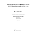
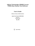
Making Connections
Connect the Test Set to the cellular telephone as shown in figure 2 .
RF IN/OUT
TO
TEST SET
Getting Started
(H
83206
T D M A CE LLU LA R A D A P T E R
PWR
RF IN/OUT
MAX.PWR 60W
CONTINUOUS
REF
UNLOCK
ANALYZER
ANALYZER
ANALYZER
GENERATOR
DATA
CLOCK IN
BASEBAND
DATA IN
TRIGGER
IN
BASEBAND
DATA IN
To Antenna
Connections
Hand held
Cellular
Telephone
Mobile
Cellular
Telephone
Antenna
Connection
Figure 2
Transportable
Cellular
Telephone
Power
Supply
Equipment Connections
23
Chapter 1, Getting Started
Setup and Software Card Loading
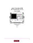
Setup and Software Card Loading
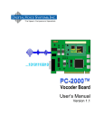
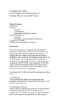
Set up the Test Set and insert the Test Software card as shown in figure 3 . The
first screen to appear during the power-up sequence is shown in figure 4 on page
25. The screen that appears when you press the TESTS key is shown in figure 5 on
page 25.
Perform steps
1-5 in order.
If after step 5, a screen
appears as shown in figure
5, power up is complete.
(H
RF IN/OUT
TO
TEST SET
1
Figure 3
24
Press
TESTS.
PRESET is a reset that
can be used at any time
to re-start.
5
4
Press
PRESET.
8320 6A
T DM A C E LL UL A R A DA P T E R
PWR
RF IN/OUT
MAX.PWR 60W
CONTINUOUS
Press
POWER.
2
REF
UNLOCK
ANALYZER
ANALYZER
ANALYZER
GENERATOR
DATA
CLOCK IN
BASEBAND
DATA IN
TRIGGER
IN
BASEBAND
DATA IN
Wait approximately 20
seconds for display to
appear (see figure 4),
then continue at step 3.
Setup and Software Loading Process
3
Insert Card HP
11807E Opt. 014.
Chapter 1, Getting Started
Setup and Software Card Loading
Getting Started
Figure 4
RX TEST Screen
Figure 5
TESTS (Main Menu) Screen
25
Chapter 1, Getting Started
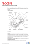
Selecting and Running the Initial Tests
Selecting and Running the Initial Tests
Perform the procedure for selecting and running the initial tests as shown in figure
6 . The screen that results from this procedure is shown in figure 7 .
1
Read information below, then begin at step 2.
2
Position the cursor at
Select Procedure Location: and select it.
4
Position the cursor at
Select Procedure Filename: and select it.
A. If you need help locating area of screen
where step is performed, see figure 5.
B. Use cursor control knob on front panel to
position cursor and make selections.
3
Position the cursor at Card and select it.
5
Position the cursor at Choices:
and select STARTED.
CP_ACCH
CP_DCCH
CP_NAMP
FUNCTNL
PARAMTR
STARTED
Figure 6
26
Selecting the Test
6
Position the cursor at Run Test and
select it. The software is now loading.
Follow screen prompts
to complete tests. At
the end of the tests, the
screen should appear
as shown in figure 7.
Chapter 1, Getting Started
Selecting and Running the Initial Tests
Getting Started
Figure 7
TESTS Screen at End of Initial Tests
27
Chapter 1, Getting Started
Selecting and Running the Initial Tests
28
2
Product Description
Product Description
29
Chapter 2, Product Description
Test Software
Test Software
The HP 11807E, Option 014, AMPS/NAMPS/DAMPS/DCCH Mobile Test
Software, in combination with the HP 8920B, Option 800, RF Communications
Test Set, forms the Test System. This system provides full functional test
capability for cellular telephones.
The Test Software can be used to test quickly the functionality of a cellular
telephone, or to test fully the parametric performance of a cellular telephone. The
Test Software is useful for cellular service providers in verifying telephone
problems, for repair centers in diagnosing problems, and for manufacturers in
fully testing telephone performance. For a complete description of each of the
Operations included in the Test Software, see chapter 4, "Operation Descriptions".
Items Included in the Test Software Package
The Test Software package includes the following items:
30
•
HP 11807E, Option 014, AMPS/NAMPS/DAMPS/DCCH Test Software One-Time
Programmable (OTP) Card -- part number 11807-10041.
•
Uninitialized Static Random-Access Memory (SRAM) Card, 64-kilobyte -- part
number HP 83230A.
•
HP 11807E, Option 014, AMPS/NAMPS/DAMPS/DCCH Software User’s Guide -part number 11807-90145.
Chapter 2, Product Description
Test Software
Software Functions
The Test Software performs the following functions:
•
•
•
Call Processing; including such items as page, origination, handoff, and release; and
involving analog and digital control channels, analog voice channels, narrow analog
voice channels, and digital traffic channels.
Functional Testing.
Parametric Testing.
Software Features
The following features simplify testing:
Test results and pass/fail indications are shown on the Test Set’s display.
•
Test results may be collected in a disk drive, SRAM card, PC, or HP Palmtop
computer.
•
Test results may be printed.
•
Test order, parameters, pass/fail limits, testing conditions, and equipment
configurations may be changed easily by the operator.
•
RF path losses may be determined and corrected.
31
Product Description
•
Chapter 2, Product Description
Hardware Considerations
Hardware Considerations
This section addresses the hardware issues relevant to operating the Test Software
in a typical application.
Applicable Hardware
The HP 11807E, Option 014 AMPS/NAMPS/DAMPS/DCCH Mobile Test
Software requires the following items for operation:
•
HP 8920B, Option 800, RF Communications Test Set (see figure 8), which consists of
the following:
HP 8920B RF Communications Test Set
HP 83206 TDMA Cellular Adapter
32
•
A cellular telephone.
•
Various adapters, cables, and other connection items (see "Equipment Required to
Get Started," in chapter 1, on page 22).
•
A power supply, if appropriate.
Chapter 2, Product Description
Hardware Considerations
Connectors, Keys, and Knobs
The following paragraphs are included here for your convenience and briefly
describe the connectors, keys, and knobs on the Test Set front and rear panels (see
figure 8). Information on these items, in much greater detail, is included in the
HP 8920B RF Communications Test Set User’s Guide. For more detailed
information on any of the items, refer to that manual.
NOTE:
Unless stated otherwise, all items are located on the Test Set’s front panel.
Product Description
33
Chapter 2, Product Description
Hardware Considerations
(H
RF IN/OUT
TO
TEST SET
23
83 206
T DM A C E LL UL A R A D A P T E R
PWR
REF
UNLOCK
ANALYZER
DATA
CLOCK IN
RF IN/OUT
MAX.PWR 60W
CONTINUOUS
ANALYZER
BASEBAND
DATA IN
ANALYZER
GENERATOR
TRIGGER
IN
BASEBAND
DATA IN
28
22
21
12
20
29
26
9
1 24 13 25 30 31
CONTROL I/O
DIAG
OUT
GEN BB
ANL
BIT CLK
DAT A OUTTRIG OUT OUT
114.3 MHz IF IN
CW
RF IN
SYMBOL
CLK OUT
2
3
34
REF IN
10 MHz
IQ
REF OUT EXT
IF IN
RF OUT
5
EXPANSION
16
SERIAL POR T
27
FRAME CLK OUT
8
11
33
17
32
7
15
14
Figure 8
34
6
10
19
Test Set Connector, Keys, and Knobs
18
4
Chapter 2, Product Description
Hardware Considerations
NOTE:
The number shown in parentheses after each item in the following paragraphs is
associated with the like-numbered pointer in figure 8.
ANT IN Connector (1)
The antenna input connector is used for analyzing low-power RF signals
(200 mW or less), typically in off-the-air measurements.
AUDIO IN HI Connector (2)
The audio high input connector is used for the audio input signal that is supplied
from the cellular telephone.
AUDIO IN LO Connector (3)
AUDIO MONITOR OUTPUT Connector (On Rear Panel) (4)
The audio monitor output connector is used to obtain an output from various tap
points in the Audio Frequency Analyzer of the Test Set. The output level is not
affected by the Test Set’s front-panel VOLUME control.
AUDIO OUT Connector (5)
The audio output connector is used for providing an audio signal to the
microphone input of a cellular telephone. The output level is not affected by the
Test Set’s front-panel VOLUME control.
CRT VIDEO OUTPUT Connector (On Rear Panel) (6)
The CRT video output connector is used to supply a signal to an external video
monitor. The signal produces a duplicate of the Test Set’s screen.
DC CURRENT MEASUREMENT Connectors (On Rear Panel) (7)
The dc current measurement connectors are used in series with an external dc
power supply and an external load to function as a 10-ampere current meter.
DC INPUT Connector (On Rear Panel) (8)
The dc input connector is used to connect power from a dc supply to the Test Set.
35
Product Description
The audio low input connector is not used with the HP 11807E, Option 014,
AMPS/NAMPS/DAMPS/DCCH Mobile Test Software.
Chapter 2, Product Description
Hardware Considerations
DUPLEX OUT Connector (9)
The duplex output connector is used to supply the signal output from the Test
Set’s RF Generator and Tracking Generator.
EXT SCOPE TRIGGER INPUT Connector (On Rear Panel) (10)
The external scope trigger input connector is used to supply a trigger to the
internal oscilloscope.
HP-IB Connector (On Rear Panel) (11)
The HP-IB connector is used to provide an interface between the Test Set and
external equipment that uses the Hewlett-Packard Interface Bus (HP-IB).
PCMCIA Card Slot (12)
The card slot is used to accept and insert a PCMCIA card to the Test Set.
MIC/ACC Connector (13)
The microphone/accessory DIN connector is used for the following functions.
•
•
•
The Mic In connection is summed with the MODULATION INPUT connector signal
to modulate the RF Generator of the Test Set when the Key In connection is grounded.
The Key In connection is used to control the RF Generator output state and to control
switching between certain screens.
The Key Out 1 and Key Out 2 connections are used to provide a switch path for external
equipment.
MODULATION INPUT Connector (On Rear Panel) (14)
The modulation input connector is used to supply an external modulation signal to
the RF Generator of the Test Set. This signal is summed with the Mic In signal
from the MIC/ACC connector.
RADIO INTERFACE Connector (On Rear Panel) (15)
The radio interface connector is used to provide a 16-line parallel interface
between the Test Set and external radio equipment. The 16 lines may be
configured as inputs, outputs, or a combination of inputs and outputs.
RF IN/OUT Connector (16)
The RF input/output connector is used to accept input RF signals to the Test Set and to
supply the output signal from the RF Generator of the Test Set.
36
Chapter 2, Product Description
Hardware Considerations
SERIAL PORT Connector (On Rear Panel) (17)
The serial port connector is used for serial data input and output in such functions
as entering programs, printing test results and screen images, and sending test
results to external equipment.
10 MHz REF INPUT Connector (On Rear Panel) (18)
The 10-MHz reference input connector is used to supply an external reference
input to the Test Set. When a valid signal is supplied through this connector, the
Test Set automatically switches from the internal to the external reference.
10 MHz REF OUTPUT Connector (On Rear Panel) (19)
The 10-MHz reference output connector is used to supply the reference signal
generated by the Test Set to external equipment.
Product Description
DATA Keys (20)
The data keys are used for the following functions:
•
The following keys are used for entering and changing values.
0 through 9
.
+/A through F
•
The ENTER key is used to select a field or screen, and to enter numbers when the unit
of measure is not specified. (Pressing this key causes the same effect as pressing the
CURSOR CONTROL knob.
•
The ON/OFF key is used to enable and disable measurements, and to turn numeric
fields on and off.
•
The YES and NO keys are used to approve or disapprove selected functions or
Operations before execution.
•
EEX (SHIFT, +/-) is used for entering numbers using scientific notation.
•
The other DATA keys are used for entering and changing the unit of measure for
measurements of field entries.
37
Chapter 2, Product Description
Hardware Considerations
DATA FUNCTIONS Keys (21)
The data functions keys are used for the following functions:
•
The INCR ÷ 10, INCR SET, and INCR × 10 keys are used to increment or decrement
a number when changing field values.
•
The up-arrow and down-arrow keys are used to increment or decrement field values, to
select alternate field entries, and to move the cursor in string entry fields.
•
The LO LIMIT (SHIFT, down-arrow) and the HI LIMIT (SHIFT, up-arrow) keys are
used to set measurement end points.
•
The REF SET (SHIFT, INCR ÷ 10) key is used to enter or remove a measurement
reference for relative audio-frequency and radio-frequency measurements.
•
The METER (SHIFT, INCR SET) key is used to enable or disable the analog bar-graph
meter function.
If the bar graph is enabled, the display consists of a bar graph section and a numeric
section that uses small digits.
If the bar graph is disabled, the display consists of only a numeric section that uses
large digits.
•
The AVG (SHIFT, INCR × 10) key is used to enable or disable measurement averaging.
INSTRUMENT STATE Keys (22)
The instrument state keys are used for the following functions:
38
•
The LOCAL key is used to return the Test Set to manual control after HP-IB control is
used.
•
The RECALL key is used to list any Test Set setups that were saved.
•
The MEAS RESET key is used to clear the measurement “history” for all of the Test
Set measurement algorithms. This restarts all measurements in progress.
•
The PRESET key is used to restore most Test Set settings to the default states. This does
not cause the Test Set’s self-diagnostics to run.
•
The ADRS (SHIFT, LOCAL) key is used to display the Test Set HP-IB address.
•
The SAVE (SHIFT, RECALL) key is used to store Test Set setups.
Chapter 2, Product Description
Hardware Considerations
SCREEN CONTROL Keys (23)
The screen control keys are used for the following functions:
•
The RX, TX, DUPLEX, TESTS, MSSG (SHIFT, RX), HELP (SHIFT, TX), and
CONFIG (SHIFT, DUPLEX) keys are used to access several Test Set control and
information screens.
•
The PREV key is used to change the display back to the previous screen.
•
The HOLD (SHIFT, PREV) key is used to stop all measurements in progress. Pressing
the key again resumes the measurements.
•
The PRINT (SHIFT, TESTS) key is used to print the entire contents of the displayed
screen, the time and date, and any defined print title.
SHIFT Key (24)
CANCEL Key (25)
The CANCEL key is used to terminate an entry in progress, or to stop a running
IBASIC program.
Left-Arrow (Backspace) Key (26)
The left-arrow key is used to move the cursor to the left when entering numbers in
a field. Each key press moves the cursor one space to the left, erasing the previous
character.
POWER switch (27)
The POWER switch is used to turn the Test Set’s power on or off.
NOTE:
Some settings and functions are retained by power from the Test Set’s back-up battery when external power is turned off.
USER Keys (28)
The USER keys (k1 through k5) are assigned specific functions by the Test
Software and are used to access immediately the assigned functions without using
the CURSOR CONTROL knob or changing screens. Note that keys can be
assigned several functions, and the specific key function is dependent upon the
Operation or function in process at the time.
39
Product Description
The SHIFT key is used to select the blue-labeled functions listed above some keys
(for instance, PRINT). Pressing and holding the SHIFT key while also pressing A
second key activates the blue-labeled function.
Chapter 2, Product Description
Hardware Considerations
CURSOR CONTROL Knob (29)
The CURSOR CONTROL knob moves the cursor to select fields, screens, and
settings from the lists of choices; and to select or change numeric field values.
Turning the knob clockwise moves the cursor to the right and down; turning it
counterclockwise moves the cursor to the left and up. Pressing the knob once
activates (selects) the function or terminates a data entry.
VOLUME Control Knob (30)
The volume control adjusts the speaker output sound level for monitoring the
selected input of the AF Analyzer.
SQUELCH Control Knob (31)
The squelch control ordinarily adjusts the squelch level in demodulating AM, FM,
or SSB signals. However, during execution of the Test Software in cellular
telephone testing, the squelch function is set to a fixed level. Thus, the squelch
control is not effective during cellular telephone testing.
Parallel Port Connector (On Rear Panel) (32)
The parallel port connector is used as an interface to printers that require a parallel
port for printing screen images or test results.
AC/DC Switch (On Rear Panel) (33)
The ac/dc switch is used to select the Test Set’s power source type. The source
type must be selected with the Test Set’s power turned off.
Chassis Ground Connector (On Rear Panel) (34)
The chassis ground connector is used for a safety ground connection when dc
power is supplied to the Test Set. This connector can be used as a general chassis
ground point.
40
Chapter 2, Product Description
Tests Subsystem
Tests Subsystem
The Tests Subsystem consists of a group of associated Test Set displays that are
used to create, edit, and run automated test procedures.
NOTE:
A test procedure consists of groups of Operations (for instance: Page, or TX RF
Power Output Test) that are performed on groups of channels (for instance: 355,
790, and 991) using specific parameters (for instance: SAT tone = 5970, or SID =
19) and specific pass/fail limits specifications (for instance: TX power at level 2).
The Operations in a procedure perform specific setup, control, or test actions.
The Tests Subsystem thus forms an easy-to-use test environment that can be used
to automate a group of Operations, with easy set up and customization of the
Operation sequence. The subsystem features are as follows:
•
Test suites.
•
Easy addition of Operations to a suite.
•
Easy deletion of Operations from a suite.
•
Easy customization of parameter values for each Operation in a suite.
•
Easy customization of global pass/fail limits specification values.
•
Large number of parameters and specifications available in the library.
•
Easy grouping of parameters and pass/fail limits according to the Operation.
•
Easy access to relevant parameters and specifications for an Operation from the setup
screen.
•
Easy customization of global parameters.
41
Product Description
The Operations described in this user’s guide are supplied on the Test Software
OTP card. These Operations are run on an HP 8920B, Option 800, RF
Communications Test Set.
Chapter 2, Product Description
Tests Subsystem
NOTE:
42
In the left-hand column in the fields sections of the screen descriptions, the following conditions apply:
•
The first term (one word or more) shown (such as “Cnfg” in the item “Cnfg [External
Devices] Field” is classed as the field title. It is always displayed and is highlighted
when the field is selected. (See the third item below for exceptions.)
•
Items shown in brackets (such as “[External Devices]” in the “Cnfg [External Devices]
Field”) are classed as explanatory words. These words are shown with the field name
on the display, but are not highlighted when the field is selected.
•
Items shown in braces (such as in “{List Number}” in the “{List Number} Field”) are
classed as undisplayed field titles. These titles are not shown on the display. However,
the field is highlighted when selected.
Chapter 2, Product Description
Tests Subsystem
Default TESTS (Main Menu) Screen
Before loading a procedure from the Test Software OTP card, the TESTS (Main
Menu) screen will be as shown in figure 9. For detailed information on the fields
of this screen, refer to the HP 8920B RF Communications Test Set User’s Guide.
Product Description
Figure 9
Default TESTS (Main Menu) Screen
Most of the fields in the HP 11807E Test Software TESTS (Main Menu) screen
described in the following sections are the same as those found in the Default
TESTS (Main Menu) screen shown above (and used with other software). The
differences occur in the lower left-hand section of the screen. Four fields that
access other screens (Freq Channel Information; Parm Test Parameters; Seqn
Order of Tests; and Spec Pass/Fail Limits) are replaced by three different fields
(Setup Chan, Seq, Parm, Spec; Parms Default Parameters; and Specs Pass/Fail
Limits). In addition, the screen accessed by the Setup Chan, Seq, Parm, Spec, in
turn, accesses another screen. Thus, the four screens accessed from the default
TESTS (Main Menu) screen are replaced by four other screens that are accessed
essentially from the HP 11807E Test Software TESTS (Main Menu) screen and
perform somewhat similar functions.
The screens that are used with software other than the HP 11807E, Option 014
Test Software are described in the HP 8920B RF Communications Test Set User’s
Guide.
43
Chapter 2, Product Description
Tests Subsystem
HP 11807E TESTS (Main Menu) Screen
When you access the Tests Subsystem by pressing the TESTS key, inserting the
HP 11807E Test Software OTP card, and selecting a procedure from the
Choices: field, the Tests Subsystem displays this TESTS (Main Menu) screen
for the HP 11807E, Option 014 Test Software (see figure 10 on page 46). This
screen then becomes the active default screen as long as a procedure filename is
selected. If a procedure filename is not selected, the original system default
TESTS (Main Menu) screen remains the default (see figure 9 on page 43).
The following paragraphs describe the various fields of this screen.
Cnfg [External Devices] Field
Selecting this field displays the TESTS (External Devices) screen.
Continue Field
Selecting this field or pressing k2 restarts a paused test.
Description: Field
Selecting this field displays a description of the file selected in the Select
Procedure Filename: field. The description is updated as a result of updating
the Select Procedure Filename: field.
Exec [Execution Cond] Field
Selecting this field displays the TESTS (Execution Conditions) screen.
Help Field
Selecting this field (or pressing k4) displays the help screen that contains
assistance information in the TESTS (Set Up) screen.
IBASIC [IBASIC Cntrl] Field
Selecting this field displays the TESTS (IBASIC Controller) screen.
Library: Field
Selecting this field displays the library information of the file chosen in the
Select Procedure Filename: field.
Parms [Default Parameters] Field
Selecting this field displays the TESTS (Default Parameters) screen, which
displays all of the parameters available in the parameters library.
44
Chapter 2, Product Description
Tests Subsystem
Print [Printer Setup] Field
Selecting this field displays the TESTS (Printer Setup) screen.
Proc [Save/Delete Procedure] Field
Selecting this field displays the TESTS (Save/Delete Procedure) screen.
Program: Field
Selecting this field displays program information for the file chosen in the
Select Procedure Filename: field. The program information is updated
automatically.
Run Test Field
Selecting this field or pressing k1 loads and runs the procedure chosen in the
Select Procedure Filename: field.
Selecting this field allows you to specify the procedure that you wish to load from
or save to the location chosen in the Select Procedure Location: field.
Selecting this field displays the Choices: field in the lower right-hand corner of
the display. The choices displayed are the procedures already available in the
selected location. If you are saving a new procedure, you may enter the new name
from the list of characters available.
Select Procedure Location: Field
Selecting this field allows you to select the location from which you wish to load a
procedure, or the location to which you wish to save a procedure. Selecting this
field displays the Choices: field in the lower right-hand corner of the display.
The choices available are: Card, ROM, RAM, and Disk.
Setup [Chan, Seq, Parm, Spec] Field
Selecting this field displays the TESTS (Set Up) screen, which functions as the
operational control for the Test Software.
Specs [Pass/Fail Limits] Field
Selecting this field displays the TESTS (Pass/Fail Limits) screen, which displays
all of the pass/fail limits specifications in the library.
45
Product Description
Select Procedure Filename: Field
Chapter 2, Product Description
Tests Subsystem
Figure 10
46
Test Software TESTS (Main Menu) Screen
Chapter 2, Product Description
Tests Subsystem
TESTS (Set Up) Screen
Access this screen by selecting the Setup Chan, Seq, Parm, Spec field of
the TESTS (Main Menu) screen.
This screen functions as the control facility for the Test Software. (Basically, this
screen combines the Order of Tests and Channel Information screens from the test
environment of earlier software, and adds the capability to loop on a group of
tests, or Operations, plus some extra usability features.)
NOTE:
This screen introduces the new term “test suite,” sometimes “suite”, to the test environment. A test suite is a set of Operations performed over a range or list of channels. (Note
that horizontal dashed lines separate test suites in the display.)
Help Field
Selecting this field (or pressing k4) displays the help screen that contains
assistance information in the TESTS (Set Up) screen.
Insert and Delete Fields
Selecting the Insert field (or pressing k1) performs an insert function when the
cursor is located in the operations field, in the channel field (in lists), or in any of
the number fields. For instance, if you wish to set up a new test suite, moving the
cursor to the Suite Number field and performing an insert function adds a test
suite. The suite added is a duplicate of the one currently in the Suite Number
field. If the cursor is located in the List Number field, performing an insert
function adds a duplicate channel in the list. If the cursor is located in the
Operation Number field, performing an insert function adds a duplicate of the
Operation currently in the active field.
Selecting the Delete field (or pressing k2) performs the opposite action to that of the
Insert key.
{List Number} Field
This is the small field to the left of the first list number in the Range/List: field
(see figure 12 on page 51). It represents the Operation list number.
Selecting this field and turning the CURSOR CONTROL knob scrolls through the
CHANNELS in the list field. This allows for adding or deleting channels
anywhere in the list.
47
Product Description
The following paragraphs describe the various fields of this screen. Two versions
of the screen are shown in figure 11 on page 50 and figure 12 on page 51.
Chapter 2, Product Description
Tests Subsystem
Main Menu Field
Selecting this field (or pressing k5) switches the display to the TESTS (Main
Menu) screen.
Operations Field
Selecting this field displays a menu that contains all of the Operations in the
library. Once you have located the desired Operation, selecting that field will
insert that Operation into the test suite.
{Operation Number} Field
This is the small field to the left of the description of the first Operation in the
Range/List: field when List is selected (see figure 12 on page 51). It displays
the Operation number in the suite.
Selecting this field and turning the CURSOR CONTROL knob scrolls through the
Operations in the test suite. This allows for adding or deleting Operations, or
changing to different Operations, anywhere in the suite.
Print All Field
Selecting this field (or pressing k3) prints all of the information in the TESTS (Set
Up) screen, including any data scrolled off the screen.
Range/List: Field
This is a toggle field that allows you to select either a range or a list of channels.
Selecting Range displays the start, stop, and Step fields (see figure 11 on page
50).
Selecting List displays a scroll box and a list field (see figure 12 on page 51).
Set Parameters Field
Selecting this field switches the display to the TESTS (Set Parameters) screen. In
this screen, you may select from Operations in the suite only, and you may set
parameters so that those parameters are uniquely defined for the Operation in that
suite. If you wish to use default parameters, pressing k1 switches the display to the
TESTS (Default Parameters) screen.
Set Pass/Fail Limits Field
Selecting this field switches to the TESTS (Pass/Fail Limits) screen. This screen
displays the specification limits associated with the Operation indicated in the
TESTS (Set Up) screen. These limits are considered to be defaults.
48
Chapter 2, Product Description
Tests Subsystem
{Start} Field
This is a five-digit field located to the left of To when Range is selected in the
Range/List: toggle field (see figure 11 on page 50). It represents the start
channel for a range. (Five digits allow for a four-digit channel number and an
optional letter U.M.L. for NAMPS or H for PCS.)
Selecting this field allows you to enter the start channel number.
Step Field
This is a four-digit field located below the start and stop fields when Range is
selected in the Range/List: toggle field. It represents the increment or step in
the range. This is an integer entry field.
Selecting this field allows you to enter the step value.
{Stop} Field
Selecting this field allows you to enter the stop channel number.
{Suite Number} Field
This is the small field to the left of the Range/List: toggle field (see figure 11
on page 50 and figure 12 on page 51). It displays the number of the test suite.
Selecting this field and turning the CURSOR CONTROL knob scrolls the test
suite information up or down in the display.
The default TESTS (Set Up) screen is shown in figure 11 on page 50.
49
Product Description
This is a five-digit field located to the right of To when Range is selected in the
Range/List: toggle field (see figure 11 on page 50). It represents the stop
channel for a range. (Five digits allow for a four-digit channel number and an
optional letter U.M.L. for NAMPS or H for PCS.)
Chapter 2, Product Description
Tests Subsystem
Figure 11
TESTS (Set Up) Screen Showing Range of Channels.
The example shown in the default TESTS (Set Up) screen above illustrates a
typical IS-136 TDMA test scenario. Selecting Main Menu from this screen, then
selecting Run Test in that menu would perform the scenario as follows:
334
001
400
700
100
200
300
400
CP Registration on ACCH
TXA Frequency Error
TXA SAT Freq Error & Deviation
TXA Frequency Error
TXA SAT Freq Error & Deviation
...
...
TXA Freq Error
TXA SAT Freq Error & Deviation
TXA RF Power Output
TXA RF Power Output
TXA RF Power Output
TXA RF Power Output
The test suite shown in figure 11 shows a range of channels highlighted. If a list of
channels is included in a selected suite, the active fields change to accommodate
this fact. The screen shown in figure 12 on page 51 illustrates a suite that shows a
list of channels highlighted.
50
Chapter 2, Product Description
Tests Subsystem
ACCH
Product Description
Figure 12
TESTS (Set Up) Screen Showing List of Channels
51
Chapter 2, Product Description
Tests Subsystem
TESTS (Specific Parameters) Screen
Access this screen by selecting the Set Parameters field in the TESTS (Set
Up) menu. It is not accessible by any other means.
This screen allows you to define specific parameter settings for the Operations in
a test suite. These new parameter settings then become the defaults for that test
suite. If you do not wish to customize the parameter values for an Operation in a
test suite, you may use the Def Parms field to set the parameters globally for all
Operations in the suite. The screen also serves to provide default settings for
specific parameters.
If, after you have completed changes to a test suite, you wish to change the
parameters in another suite, you must return to the TESTS (Set Up) menu to select
that suite, then return to this menu.
The following paragraphs describe the various fields of this screen (see figure 13
on page 54, figure 14 on page 54, figure 15 on page 55, figure 16 on page 55, and
figure 17 on page 56).
Apply Def Field
Selecting this field (or pressing k2) resets the parameter settings for the selected
Operation to the default settings specified in the defaults menu.
Def Parms Field
Selecting this field (or pressing k1) switches the display to the TESTS (Default
Parameters) screen. This allows you to edit the default parameters.
Help Field
Selecting this field (or pressing k4) displays the help screen that contains
assistance information in the TESTS (Specific Parameters) screen.
{Operation List} Field
This is the field at the top left of the display (see figure 13 on page 54). It identifies
the Operation for which the parameter value can be set. The Operation indicated
in this field is associated with the test suite identified in the TESTS (Set Up)
screen.
Selecting this field displays a menu that contains all of the Operations in the suite.
This allows you to create your own set of parameter values for any Operation in
the suite. Changing an Operation in this field updates the screen to display the
relevant parameters for the selected Operation.
52
Chapter 2, Product Description
Tests Subsystem
{Parameter Number} Field
This is the field at the middle left of the display (see figure 13 on page 54). It
identifies the parameter number.
Selecting this field and turning the CURSOR CONTROL knob scrolls through the
parameters for the Operation.
Print All Field
Selecting this field (or pressing k3) prints the suite number and the Operation,
with its associated parameters and values. (The Operation numbers for a suite
must be identified to distinguish between parameter values in suites that use an
Operation multiple times.)
Setup Field
{Value} Field
This is the field at the middle left of the display, just to the right of and slightly
below the Parameter Number field (see figure 13 on page 54, figure 14 on page 54,
figure 15 on page 55, figure 16 on page 55, and figure 17 on page 56). This field is a
variable type, and changes according to the kind of value. For instance, if the
value is a toggle, the field is represented as a toggle; if the value is a numeric
quantity, it is represented as such. It can be any of the four following types,
dependent upon the specific parameter: Choices (see figure 14 on page 54 ), Toggle
(see figure 15 on page 55), Numerical Entry (Float) (see figure 16 on page 55), or
Integer (see figure 17 on page 56). The definitions are self-explanatory.
Selecting the available field allows you to set the appropriate value.
53
Product Description
Selecting this field (or pressing k5) switches the display to the TESTS (Set Up)
screen.
Chapter 2, Product Description
Tests Subsystem
Figure 13
TESTS (Specific Parameters) Screen
Figure 14
TESTS (Specific Parameters) Screen Showing Choices
54
Chapter 2, Product Description
Tests Subsystem
TESTS (Specific Parameters) Screen Showing Toggle
Figure 16
TESTS (Specific Parameters) Screen Showing Numerical Entry
Product Description
Figure 15
55
Chapter 2, Product Description
Tests Subsystem
Figure 17
56
TESTS (Specific Parameters) Screen Showing Integer
Chapter 2, Product Description
Tests Subsystem
TESTS (Default Parameters) Screen
Access this screen by selecting the Parms Default Parameters field in the
TESTS (Main Menu) screen.
This screen displays all of the parameters available in the library, grouped by
Operation. Selecting the Operation from the menu updates the screen to display
all of the relevant parameters for that Operation. Any of the Operations in the
library may be selected.
Defaults may be changed to create a tailored set of defaults that apply to all of the
parameters specific to an Operation. Defaults are used as initial settings for all
Operations. If a parameter in an Operation is changed using the TESTS (Specific
Parameters) screen, that parameter value is used as the default when the Operation
is used in a test suite.
Help Field
Selecting this field (or pressing k4) displays the help screen that contains assistance
information in the TESTS (Default Parameters) screen.
{Operation} Field
This is the field near the top of the display (see figure 18 on page 59). It identifies the
Operation for which the parameter values can be set.
Selecting this field and turning the CURSOR CONTROL knob scrolls through a menu
that contains all of the Operations in the library. Selecting an Operation in the menu
updates the screen to display the relevant parameters for that Operation.
{Parameter Number} Field
This is the small field at the left side near the middle of the display (see figure 18 on page
59). It identifies the parameter number.
Selecting this field and turning the CURSOR CONTROL knob scrolls through the
parameters for the Operation.
Print Tst Field
Selecting this field (or pressing k3) prints all of the default parameters for the selected
Operation.
57
Product Description
The following paragraphs describe the various fields of this screen (see figure 18
on page 59, figure 19 on page 59 , figure 20 on page 60, figure 21 on page 60 , and
figure 22 on page 61).
Chapter 2, Product Description
Tests Subsystem
Reset All Field
Selecting this field (or pressing k2) applies the parameter value in the currently
selected Operation to all occurrences of the parameter in any Operation in the
TESTS (Set Up) screen. For instance, if Page is selected and parameter three is
changed from Yes to No, and parameter three is used in several Operations, then
parameter three will be changed to No in each of those Operations. This change
can be verified by switching to the TESTS (Specific Parameters) screen for any
suite that uses a Page Operation and verifying that the value has been updated.
Selecting this field also results in a user prompt to verify that the change is
desired.
NOTE:
The differences between the Reset All and Reset One functions are somewhat subtle. Read
these two descriptions very carefully, especially the underlined words.
Reset One Field
Selecting this field (or pressing k1) applies the parameter value in the currently
selected Operation to each occurrence of the parameter in each occurrence of the
selected Operation in the TESTS (Set Up) screen. For instance, if Page is selected
and parameter three is changed from Yes to No, then parameter three will be
changed to No for every Page Operation in the TESTS (Set Up) menu. This
change can be verified by switching to the TESTS (Specific Parameters) screen
for any suite that uses a Page Operation and verifying that the value has been
updated. Selecting this field also results in a user prompt to verify that the change
is desired.
Setup Field
Selecting this field (or pressing k5) switches the display to the TESTS (Set Up) screen.
{Value} Field
This is the field at the middle left of the display, just to the right of and slightly
below the Parameter Number field (see figure 18 on page 59, figure 19 on page 59,
figure 20 on page 60, figure 21 on page 60, and figure 22 on page 61). This field is a
variable type, and changes according to the kind of value. For instance, if the
value is a toggle, the field is represented as a toggle; if the value is a numeric
quantity, it is represented as such. It can be any of the four following types,
dependent upon the specific parameter: Choices (see figure 19 on page 59), Toggle
(see figure 20 on page 60), Numerical Entry (Float) (see figure 21 on page 60), or
Integer (see figure 22 on page 61). The definitions are self-explanatory.
Selecting the available field allows you to set the appropriate value.
58
Chapter 2, Product Description
Tests Subsystem
TESTS (Default Parameters) Screen
Figure 19
TESTS (Default Parameters) Screen Showing Choices
Product Description
Figure 18
59
Chapter 2, Product Description
Tests Subsystem
Figure 20
TESTS (Default Parameters) Screen Showing Toggle
Figure 21
TESTS (Default Parameters) Screen Showing Numerical Entry
60
Chapter 2, Product Description
Tests Subsystem
Product Description
Figure 22
TESTS (Default Parameters) Screen Showing Integer
61
Chapter 2, Product Description
Tests Subsystem
TESTS (Set Up Pass/Fail Limits) Screen
Access this screen by selecting the Specs Pass/Fail Limits field in the TESTS
(Main Menu) screen.
This screen displays all of the Operation pass/fail limits specifications available in the
library, grouped by Operation. Selecting the Operation from the menu updates the screen
to display all of the relevant pass/fail limits specifications for the Operation. Any of the
Operations in the library may be selected.
Defaults may be changed to create a tailored set of pass/fail limits specifications that apply
to all of the Operations.
The following paragraphs describe the various fields of this screen (see figure 23 on page
63).
Check Field
Selecting this field allows you to select whether the Operation will verify only the
upper, only the lower, both, or none of the specified limits. Selecting both upper
and lower limits increases test time, but might be required for some Operations.
Help Field
Selecting this field (or pressing k4) displays the help screen that contains assistance
information in the TESTS (Set Up Pass/Fail Limits) screen.
Lower Limit Field
Selecting this field allows you to set the lower limit to be compared with the
measured result. If the measured result is below this limit, the test fails.
{Operation} Field
This is the field near the top of the display (see figure 23 on page 63). It identifies the
Operation for which the parameter values can be set.
Selecting this field and turning the CURSOR CONTROL knob scrolls through a menu
that contains all of the Operations in the library. Selecting an Operation in the menu
updates the screen to display the relevant pass/fail limits specifications for that Operation.
Print All Field
Selecting this field (or pressing k3) prints all of the pass/fail limits specifications for all of
the Operations identified in the TESTS (Set Up) screen. The printout will indicate the
Operation name and its associated pass/fail limits.
62
Chapter 2, Product Description
Tests Subsystem
Print Tst Field
Selecting this field prints the pass/fail limits specifications for the current
Operation only. The printout is similar to the display.
Setup Field
Selecting this field (or pressing k5) switches the display to the TESTS (Set Up) screen.
{Specification Number} Field
This is the small field at the left side near the middle of the display (see figure 23
on page 63). It represents the pass/fail limits specification number.
Selecting this field and turning the CURSOR CONTROL knob scrolls through the
pass/fail limits specifications for the Operation.
Upper Limit Field
Figure 23
TESTS (Set Up Pass/Fail Limits) Screen
63
Product Description
Selecting this field allows you to set the upper limit to be compared with the
measured result. If the measured result is above this limit, the test fails.
Chapter 2, Product Description
Tests Subsystem
64
3
Using the Software
Using the Software
69
Chapter 3, Using the Software
Introduction
Introduction
This chapter provides detailed information on loading, running, and customizing
test procedures.
The HP 11807E, Option 014, AMPS/NAMPS/DAMPS/DCCH Mobile Test
Software operates under control of various test suites, Operations, parameters, and
pass/fail limits specifications. These are defined in two ways. In the first, the Test
Software includes factory default settings that you may use without change. In the
second, you may customize the settings to your specific requirements.
The Test Set includes also two methods for accessing on-line help. In the first, in
each of the screens in the test environment, pressing the k4 (Help) key accesses
specific information about procedures to set up and use the current screen. In the
second, pressing the SHIFT key, then the TX key accesses the master help file,
which includes an alphabetical listing of help topics about the Test Set.
NOTE:
70
Special presentations of text in this manual are as shown in "Conventions" on page
4.
Chapter 3, Using the Software
Connecting Equipment
Connecting Equipment
Various cables and adaptors are required to connect the Test Set to the cellular
telephone and to other equipment. Interconnections are shown in figure 25 on page
72. Cable descriptions and part numbers are listed in table 2 on page 73 and table 3
on page 74.
CAUTION:
The Test Set can be damaged by transient RF power, excessive continuous RF power, high
voltage, and electrostatic discharge from cables and other sources.
Observe proper grounding techniques and exercise care in connecting and
applying power to the Test Set and ancillary equipment.
Using the Software
71
Chapter 3, Using the Software
Connecting Equipment
(H
RF IN/OUT
TO
TEST SET
83206
T D M A CE LLU LA R A D A P T E R
PWR
REF
UNLOCK
RF IN/OUT
MAX.PWR 60W
CONTINUOUS
ANALYZER
ANALYZER
ANALYZER
GENERATOR
DATA
CLOCK IN
BASEBAND
DATA IN
TRIGGER
IN
BASEBAND
DATA IN
AUDIO OUT
RF IN/OUT
HI
1
Antenna
2
4
For more information,
see the descriptions
for Operations that
test at extreme
voltage settings.
HP-IB DC Power
Supply (Optional)
Figure 25
72
Equipment Connections
3
Cellular
Telephone
3
3
Transmit
Audio
Receive
Audio
GND
GND
Chapter 3, Using the Software
Connecting Equipment
Cellular Telephone to Test System Connections
Table 2 lists the equipment required for connecting the cellular telephone to the
Test System.
Table 2
Reference #
Cables and Connectors
Description
Purpose
Quantity
Needed
Part Number
1
BNC(f) to Type
N(m) adapter
Adapt BNC cable to RF
IN/OUT
1
HP 1250-0780
2
BNC(f) to TNC(m)
adapter or
BNC(f) to miniUHF(m) adapter,
depending on cellular
telephone
Adapt BNC cable to
antenna out
1
HP 1250-2441 for
TNC only or
Tessco part #74720
3
BNC(m) to BNC(m)
cable,
1.2 meters (4 feet)
Antenna and audio
3
HP 10503A
4
HP-IB Interface
cable,
1 meter (3.3 feet)
Test system HP-IB to
power supply HP-IB
1
HP 10833A
Using the Software
73
Chapter 3, Using the Software
Connecting Equipment
Test System to Printer Connections
Table 3 lists cables available from Hewlett-Packard for connection to HewlettPackard printers.
Table 3
Hewlett-Packard Printer Cables
Description
74
HP Model
Number or
Part Number
Purpose
Quantity
HP-IB (IEEE 488) Cable,
1 meter (3.3 feet)
Test Set to HP-IB Printer
1
10833A
HP-IB (IEEE 488) Cable,
2 meters (6.6 feet)
Test Set to HP-IB Printer
1
10833B
Parallel (IEEE 1284) Printer
Cable,
2 meters (6.6 feet)
Test Set to Parallel
(Centronics) Printer
1
C2950A
Parallel (IEEE 1284) Printer
Cable,
3 meters (9.9 feet)
Test Set to Parallel
(Centronics) Printer
1
C2951A
Serial Printer Cable,
4-pin RJ-11 (male) to
9-pin DB-9 (female),
2 meters (6.6 feet)
Test Set to Serial Printer
(with 9-pin connector)
1
08921-61038
Serial Printer Cable,
4-pin RJ-11 (male) to
25-pin DB-25 (male),
3 meters (9.9 feet)
Test Set to Serial Printer
(with 25-pin connector)
1
08921-61039
Chapter 3, Using the Software
Connecting Equipment
Audio Connections
Audio connections are used for only the following Operations:
TXA Audio Distortion
TXA Audio Frequency Response
TXA Hum and Noise
TXA Modulation Deviation Limiting on Analog Voice Channel
TXA Modulation Deviation Limiting on Narrow Analog Voice Channel
RXA Audio Distortion
RXA Audio Frequency Response
RXA Expandor
RXA Hum and Noise
RXA Sensitivity (SINAD)
RXA Sensitivity (SINAD), Narrow Analog Voice Channel
RXA Sensitivity versus Channel (Plotted)
The method of the audio connections is dependent on the cellular telephone being
tested. Consult the telephone manufacturer’s documentation for the correct
method. Some manufacturers provide a method for audio signal breakout; others
require that the audio lines to the cellular telephone be tapped or an acoustic
coupler be used on the handset.
Using the Software
75
Chapter 3, Using the Software
Calibrating Cable Loss
Calibrating Cable Loss
Inaccuracies can occur in your RF measurements because of cable losses and
impedance mismatches. Thus, the following two steps are required for accurate
testing.
1. Measure or calculate losses to arrive at a calibration factor for RF cables, connectors,
and adapters using standard techniques and methods.
2. Include this calibration factor in the Cable Loss parameter in the GEN Modify
Execution Parameters Operation (see "GEN Modify Execution Parameters" on page
114).
NOTE:
76
The Test Software includes a default calibration factor. If you do not provide specific
information, the tests will be run using the default factor.
Chapter 3, Using the Software
Testing Overview
Testing Overview
The overall testing process is shown in figure 26 on page 79 and described in the
following paragraphs.
NOTE:
Before beginning testing, you must have loaded the Test Software, as described in
chapter 1, "Getting Started," on page 19, and completed the equipment connections
(see "Connecting Equipment" on page 71).
Pressing the TESTS key displays the TESTS (Main Menu) screen. From the
TESTS (Main Menu) screen, you must select a procedure from the Choices:
field (to access the TESTS Subsystem), and then you may select one of the
following three options:
Begin testing:
•
If the factory default settings are acceptable for your application, you may simply start
testing using those defaults.
•
If the Test Software has already been customized and saved to an SRAM card, you may
start testing using the custom procedures.
Using the Software
77
Chapter 3, Using the Software
Testing Overview
Customize the Test Software:
In the CUSTOMIZE TEST PROCEDURE: list, select the TESTS Subsystem
processes by which you wish to change the procedure. For detailed information on
the TESTS Subsystem, see chapter 2, "Product Description".
•
If you wish to specify a new list of Operations, or change the current list of Operations,
or change the sequence of the Operations, select the Setup Chan, Seq, Parm,
Spec field to display the TESTS (Set Up) screen.
•
If you wish to change specific parameters, select the Setup Chan, Seq, Parm,
Spec field, then select the Set Parameters field in the TESTS (Set Up) screen to
display the TESTS (Specific Parameters) screen.
•
If you wish to specify a new range or list of channels to test, or change the current list,
select the Setup Chan, Seq, Parm, Spec field to display the TESTS (Set Up)
screen, then the Range or List field in that screen.
•
If you wish to change the test environment and conditions, select the Parms
Default Parameters field to display the TESTS (Default Parameters) screen.
•
If you wish to change the pass/fail limits specifications for specific measurements,
select the Specs Pass/Fail Limits field to display the TESTS (Pass/Fail
Limits) screen.
•
If you wish to save any or all of the above customized changes to an SRAM card, or
delete any from the card, select the Proc Save/Delete Procedure field to
display the TESTS (Save/Delete Procedure) screen.
Set up the Test Set for printing results:
78
•
If you wish to print test results or certain screens, select the Print Printer Setup
field in the TESTS (Main Menu) screen.
•
If you wish to select when and where test results are to be displayed, select the Exec
Execution Cond and Print Printer Setup fields, as appropriate, in the
TESTS (Main Menu) screen.
Chapter 3, Using the Software
Testing Overview
To Run Tests
Connect Cables
Load Software
H
Customize Testing
Select a test
procedure
See page
TESTS (Set Up) Screen
See page 47
81
TESTS (Specific
Parameters) Screen
See page 52
Yes
Customize?
Using the Software
No
TESTS (Default
Parameters) Screen
See page 57
Run Tests
TESTS (Pass/Fail Limits)
Screen
See page 62
Figure 26
Testing Overview
79
Chapter 3, Using the Software
Testing Overview
Before Running Tests
Select a procedure from the HP 11807E, Option 014,Test Software OTP card. The Test
Software is shipped with the following preprogrammed procedures:
CP_ACCH -- Contains call processing tests using an analog control channel.
CP_DCCH -- Contains call processing tests using a digital control channel.
CP_NAMP -- Contains call processing tests using Narrow Analog Voice Channels and
Wide Analog Voice Channels.
FUNCTNL -- Contains RF and parametric tests. No audio functions are required.
PARAMTR -- Contains parametric tests including RF, audio, and call processing.
Audio connections are required.
STARTED -- Contains five tests used in chapter 1, "Getting Started".
Before you begin testing, you should have made the appropriate hardware connections.
See "Connecting Equipment" on page 71.
80
Chapter 3, Using the Software
Testing Overview
Selecting a Test Procedure
To load the test procedure (see figure 27 on page 82), you must first select the
location from which to load (ordinarily, it will be Card). Then, you must select a
procedure filename. The OTP card that contains your Test Software also contains
several pre-programmed procedures. Finally, you must start the procedure.
NOTE:
The Test Software code is not loaded into the Test Set’s memory until you press
the k1 (Run Test) key. It will then take approximately 15 seconds to load the
code.
You may remove the Test Software OTP card after the software code is loaded
into the Test Set’s memory. The procedure and code will remain in memory after
a power-down/power-up cycle unless it is manually deleted or a new procedure is
loaded.
When the procedure begins to run, the Operations are executed in the order of
entry into the procedure.
You may press the CANCEL key at any time to pause the current procedure, then
press the k2 (Continue) key to resume it.
Using the Software
81
Chapter 3, Using the Software
Testing Overview
1
Read the information below, then begin at
step 2.
2
Position the cursor at
Select Procedure Location: and select it.
4
Position the cursor at
Select Procedure Filename: and select it.
A. If you need help locating area of screen
where step is performed, see Figure 5.
B. Use cursor control knob on front panel to
position cursor and make selections.
3
Position the cursor at Card and select it.
5
Position the cursor at Choices: and select
the desired procedure.
CP_ACCH
CP_DCCH
CP_NAMP
FUNCTNL
PARAMTR
Figure 27
82
Selecting a Test Procedure
6
Position the cursor at Run Test and
select it. The software is now loading.
Follow the screen
prompts. When
testing is complete,
test results will be
displayed on the
screen.
Chapter 3, Using the Software
Using Common Processes
Using Common Processes
This section includes descriptions of the more commonly useful processes
available for using the Test Software. These descriptions are selected for inclusion
here because you will probably use most in your everyday applications. Other
processes that are not used very often are described in chapter 6, "Reference" on
page 309.. The descriptions are presented in alphabetical order as follows:
•
Exiting a Procedure
•
Pausing, Stopping, or Continuing a Procedure
•
Printing
•
Setting Test Execution Conditions
•
Using Procedures
•
Verifying and Editing Parameters
•
Verifying and Editing Pass/Fail Limits Specifications
Using the Software
83
Chapter 3, Using the Software
Using Common Processes
Exiting a Procedure
To exit a procedure, either:
Press the CANCEL key to pause the procedure.
NOTE:
At this point, the procedure is stopped. You may elect to restart the procedure (see
"Pausing, Stopping, or Continuing a Procedure" on page 85), but be aware that
subsequent testing might be unpredictable.
or,
Press the SHIFT key, then the CANCEL key, to stop the procedure. This performs an
IBASIC RESET function.
84
Chapter 3, Using the Software
Using Common Processes
Pausing, Stopping, or Continuing a Procedure
To pause a procedure:
Press the CANCEL key or
Press the k2 (Stop Test) key.
NOTE:
At this point, the procedure is stopped. You may elect to restart the procedure, but be aware
that subsequent testing might be unpredictable.
To stop a procedure:
Press the SHIFT key, then the CANCEL key. (This performs an IBASIC RESET
function.) or
Press the k1 (Stop Test) key twice.
NOTE:
If you make changes to instrument settings while the procedure is paused, subsequent
testing might be unpredictable. Error messages might be displayed. See "Exiting a
Procedure" on page 84.
To continue a paused procedure:
1. Press the TESTS key (if the TESTS (Main Menu) screen is not being displayed).
2. Press the k2 (Continue) key.
85
Using the Software
The test time is displayed when the procedure is completed. This time includes the
period during which the procedure is paused and the period during which it is
waiting for connection and inputs to be completed. If a procedure is run through
midnight, the test time will not display properly.
Chapter 3, Using the Software
Using Common Processes
Printing
You may print any of the following:
•
Test results
•
TESTS screens
•
TESTS (Set Up)
•
TESTS (Specific Parameters)
•
TESTS (Default Parameters)
•
TESTS (Pass/Fail Limits)
There are six basic steps to the printing process. For more detailed information on
each of these steps, see "Printing," in chapter 6, on page 333 .
To print test results or screens:
1. Verify that your printer is supported by the Test Set (see "Supported Printers," in
chapter 6, on page 333).
2. Determine if your printer requires serial, parallel, or HP-IB connection (see the printer
documentation).
3. Connect the printer to the appropriate port on the Test Set (see "Printing," in chapter
6, on page 333).
4. Configure the Test Set for your printer and its interface (see "Configuring the Test Set
for Printing," in chapter 6, on page 336).
5. Direct the Test Set as to what to print (see "Printing," in chapter 6, on page 333.
6. Select the desired value in the Print Opt’s parameter for controlling printing (see "GEN
Modify Execution Parameters," in chapter 4, on page 114.)
86
Chapter 3, Using the Software
Using Common Processes
Setting Test Execution Conditions
Test execution conditions define where and when test results output occurs. In
some situations, you may wish to change the way the Test Software operates
when a test result is obtained. Test execution conditions allow you to do this and
are accessed from the TESTS (Main Menu) screen. Test execution conditions are
not retained after a power-down and power-up cycle.
1. Press the TESTS key. The TESTS (Main Menu) will appear.
2. Move the cursor to the Exec Execution Cond field in the SET UP TEST SET:
list and select it to switch to the TESTS (Execution Conditions) screen.
3. Change the settings in the screen as required.
The fields in the TESTS (Execution Conditions) screen in which you may change
conditions are described in the following paragraphs:
Output Results To: Field
You may select either Crt or Printer. The default is Crt.
You may specify where test results are to be placed. If you select Crt, results will
be displayed on the Test Set’s screen. If you select Printer, test results will be
sent to the display and to a printer. You must connect and configure a printer if
you select Printer. See "Printing" on page 86 and see "Printing," in chapter 6, on
page 333.
Output Results For: Field
You may specify if you wish to display or print only the failed results. This will be
useful if you generally do not print test results, and wish to ensure that failure
results are displayed or printed.
Output Heading: Field
You may use this field to enter a heading to be printed or displayed.
Select the field, then use the CURSOR CONTROL knob to select from the list of
characters in the Choices: field and enter the characters that you wish to appear
in the heading.
Select Done when you have finished.
87
Using the Software
You may select either All or Failures. The default is All.
Chapter 3, Using the Software
Using Common Processes
If Unit-Under-Test Fails: Field
You may select either Continue or Stop. The default is Continue.
If you select Stop, and a pass/fail result is F, the program will stop.
Test Procedure Run Mode: Field
You may select either Continuous or Single Step. The default is
Continuous.
You may command testing to pause at certain times. If you set this mode to
Single Step, the procedure will pause after a comparison is made between a
test determination and the expected result. For example, Operations will pause
after the procedure compares the results to a specification. You may continue the
Operation from the paused state by pressing the k2 (Continue) key.
Autostart Test Procedure on Power-Up: Field
You may select either On or Off. The default is Off.
You may set up the Test Set so that, if the procedure was previously loaded, the
procedure will be immediately executed when the Test Set is powered on.
88
Chapter 3, Using the Software
Using Common Processes
Using Procedures
A procedure is a collection of Operations and an order of Operations, all
contained in a file that customizes the Test Software to a specific application. You
may save the file on an SRAM card or an external disk drive.
When you save a procedure, it includes a list of Operations (each of which
includes channel and other communications information, parameters, and pass/fail
limits specifications), an order of Operations, plus a library that contains the
names of all Operations, parameters, and pass/fail limits specifications that are
resident in the Test Software. The library file is part of the Test Software and
cannot be modified. The library file is saved automatically on the card or disk that
is being used to store the new procedure.
The procedures supplied with the Test Software are listed in the Choices: field
when you select the Select Procedure Filename: field. Procedures are
displayed only if the Test Software OTP card is inserted.
Saving a Procedure
After you have set up the Test Software, you may save the procedure to an SRAM
card, external disk drive, or internal RAM.
The SRAM card, external disk drive, or RAM disk that you use must be initialized
before its first use. See "Initializing an SRAM Card," in chapter 6, on page 330 , or
see "Initializing a Disk," in chapter 6, on page 324 or see "Initialize RAM disk
Volume 0 as follows:," in chapter 6, on page 342.
Using the Software
89
Chapter 3, Using the Software
Using Common Processes
To save a procedure:
1. Press the TESTS key. The TESTS (Main Menu) screen will appear.
If you intend to select any item other than Disk in step 4, proceed to step 2 now.
If you intend to select Disk in step 4, perform the following four sub-steps to enter the
disk specification, then proceed to step 2.
a. Move the cursor to the Cnfg External Devices field in the CUSTOMIZE
TEST PROCEDURE: list and select it to switch to the TESTS (External Devices)
screen.
b. Move the cursor to the External Disk Specification field and select it.
c. From the list of characters in the Choices: field, enter the disk
specification. When the specification is complete, move the cursor to Done
and select it.
d. Press the k5 (Main Menu) key to return to the TESTS (Main Menu) screen.
2. Move the cursor to the Proc Save/Delete Procedure field in the CUSTOMIZE
TEST PROCEDURE: list and select it to switch to the TESTS (Save/Delete Procedure)
screen.
3. Move the cursor to the Select Procedure Location: field and select it.
4. From the Choices: field, select the desired location.
5. Move the cursor to the Enter Procedure Filename: field and select it.
6. From the list of characters in the Choices: field, enter a filename. When the filename
is complete, move the cursor to Done and select it.
NOTE:
A procedure file name must be nine characters or less. Procedure file names that already
exist on the card will appear at the top of the list of characters.
7. If you selected Card, insert an initialized SRAM card into the card slot on the Test
Set’s front-panel.
8. Verify that the card or other medium is not write-protected. See "Memory Cards," in
chapter 6, on page 327.
9. Move the cursor to the Enter Description for New Procedure: field and
select it. From the list of characters in the Choices: field, enter comments. When the
comments are complete, move the cursor to Done and select it.
10. Move the cursor to the Procedure Library: field and select Current (the
default). The name of the Library is displayed in the TESTS (Main Menu) screen.
11. Move the cursor to the Proc field and select it.
12. Press the k1 (Save Proc) key. The procedure will be saved at the location that you
selected.
90
Chapter 3, Using the Software
Using Common Processes
Loading a Procedure
A procedure can be loaded from another storage medium into the Test Set’s
battery-backed-up memory.
To load a procedure:
1. Press the TESTS key. The TESTS (Main Menu) screen will appear.
2. Move the cursor to the Select Procedure Location: field and select it.
3. From the Choices: field, select the desired location.
4. Move the cursor to the Select Procedure Filename: field and select it.
5. From the Choices: field, select the procedure that you wish to load.
6. Read the Description: field to ensure that the procedure that you have chosen is
the one that you wish to load.
Deleting a Procedure
Procedures can be removed from an SRAM card, external disk drive, or RAM
disk at any time.
To delete a procedure:
1. Press the TESTS key. The TESTS (Main Menu) screen will appear.
2. Move the cursor to the Select Procedure Location: field and select it.
3. From the Choices: field, select the desired location.
4. Move the cursor to the Proc Save/Delete Procedure field in the CUSTOMIZE
TEST PROCEDURE: list and select it to switch to the TESTS (Save/Delete Procedure)
screen.
6. From the Choices: field, select the name of the procedure that you wish to delete.
7. Press the k2 (Del Proc) key.
8. Press the Yes key.
Securing and Un-Securing a Procedure
After you have set up your Test Software with a test suite, channel information,
parameters, and pass/fail limits specifications, you might wish to secure it. This
will prevent viewing and changing those functions. You may select the items to
secure or un-secure. The IBASIC ROM program to perform this function is
included in the Test Set.
91
Using the Software
5. Move the cursor to the Enter Procedure Filename: field and select it.
Chapter 3, Using the Software
Using Common Processes
You may secure the procedures that are supplied with the Test Software. These
are shipped un-secured.
To secure a procedure:
1. Press the TESTS key. The TESTS (Main Menu) screen will appear.
2. Move the cursor to the Select Procedure Location: field and select it.
3. From the Choices: field, select ROM.
4. Move the cursor to the Select Procedure Filename: field and select it.
5. From the Choices: field, select IB_UTIL.
6. Press the k1 (Run Test) key.
7. Select the location of the procedure that you wish to secure by pressing the k1 key for
SRAM card, or the k2 key for RAM.
NOTE:
RAM refers to the RAM disk memory in the Test Set. Before selecting RAM for the first
time, you must initialize the RAM as a disk. See "Initialize RAM disk Volume 0 as
follows:," in chapter 6, on page 342
8. Proceed with the displayed instructions. If you wish to secure only one of the items,
such as pass/fail limits specifications, this is permissible.
9. When you are prompted to enter the pass number, enter any sequence of numerals
0 through 9 using the DATA keypad. Enter 9 digits or less. Record this number for
future use.
92
Chapter 3, Using the Software
Using Common Processes
To un-secure a procedure:
NOTE:
To un-secure a procedure, you must know the pass number of that procedure.
1. Press the TESTS key. The TESTS (Main Menu) screen will appear.
2. Move the cursor to the Select Procedure Location: field and select it.
3. From the Choices: field, select ROM.
4. Move the cursor to the Select Procedure Filename: field and select it.
5. From the Choices: field, select IB_UTIL.
6. Press the k1 (Run Test) key.
7. Select the location of the procedure that you wish to un-secure by pressing the k1 key
for SRAM card or the k2 key for RAM.
8. Enter the name of the procedure that you wish to un-secure.
9. If the procedure has any item secured, you will be prompted for the pass number.
10. Proceed with the displayed instructions. Select the items that you wish to un-secure.
11. When you are prompted, enter the pass number using the DATA keypad. Press the
ENTER key when the entry is complete.
Using the Software
93
Chapter 3, Using the Software
Using Common Processes
Verifying and Editing Parameters
Parameters are values that you enter to optimize your use of the Test Software.
Many of the parameters are determined by examining your testing needs.
Default values are included in the Test Software. Some of these values have been
derived from standard methods of measurement and some are derived from
industry standard requirements. Each Operation includes applicable parameters. It
is not necessarily required that you change these parameters when you select an
Operation or change the Operations in your procedure. However, it might be
desirable to change one or more to reflect the desired testing regimen. A list of the
parameters used is included in each of the Operation descriptions in chapter 4,
"Operation Descriptions" on page 105..
NOTE:
You must first select and load a Procedure to access the TESTS Subsystem. In the case of
verifying and editing parameters, the procedure that you select contains the default
parameters, grouped by Operation. You may then select the Parms Default
Parameters field in the CUSTOMIZE TEST PROCEDURE: list to switch to the TESTS
(Default Parameters) screen and edit the default values.
You should verify that parameters are set properly after you select the Operations
to be placed in your procedure.
A lock is provided in the Test Software to prevent uncontrolled access to the
parameters. See "Securing and Un-Securing a Procedure" on page 91.
Each parameter remains in battery-backed-up memory until you select a another
procedure to run. If you wish to prevent its loss when you select a new procedure,
you must save it in a procedure (See "Saving a Procedure" on page 89 ). If you wish
to print the parameters list, see "Printing" on page 86.
To edit a parameter value:
NOTE:
The appropriate procedure filename must be selected before editing a parameter value. If
this has not been done already, perform the following steps:
1. Press the TESTS key. The TESTS (Main Menu) screen will appear.
2. Move the cursor to the Select Procedure Location: field and select it.
3. From the Choices: field, select Card for the location at which the procedure is
stored.
4. Move the cursor to the Select Procedure Filename: field and select it.
94
Chapter 3, Using the Software
Using Common Processes
If the appropriate procedure filename is already selected, edit the value as follows:
1. Move the cursor to the Parms Default Parameters field in the CUSTOMIZE
TEST PROCEDURE: list and select it to switch to the TESTS (Default Parameters)
screen.
2. Move the cursor to the Operation field and select it.
3. Rotate the CURSOR CONTROL knob to the desired Operation and select it.
4. Move the cursor to the Parameter Number field and select it.
5. Move the cursor to the Value field of the parameter to be changed and select it.
6. Enter the desired value using the DATA keypad, then press the ENTER key.
•
Use the backspace key to correct entries.
•
Press the CANCEL key to cancel entries and retain the old value.
7. Press the k5 (Main Menu) key (or the TESTS key) to return to the TESTS (Main
Menu) screen.
Using the Software
95
Chapter 3, Using the Software
Using Common Processes
Verifying and Editing Pass/Fail Limits Specifications
Pass/fail limits are values that you enter to optimize your use of the Test Software.
Many of the pass/fail limits specifications are determined by examining your
testing needs.
Default values are available in the Test Software. Some of these values have been
derived from standard methods of measurement and some are derived from
industry standard requirements. Each Operation includes applicable pass/fail
limits specifications. It is not necessarily required that you change these pass/fail
limits specifications when you select an Operation or change the Operations in
your procedure. However, it might be desirable to change one or more to reflect
the desired testing regimen. A list of the pass/fail limits specifications used is
included in each of the Operation descriptions in chapter 4, "Operation
Descriptions" on page 105.
NOTE:
You must first select and load a Procedure to access the TESTS Subsystem. You may then
select the TESTS (Pass/Fail Limits) screen from the CUSTOMIZE TEST PROCEDURE:
list to see and edit the default values.
You should verify that pass/fail limits specifications are set properly after you
select the Operations to be placed in your procedure.
A lock is provided to prevent uncontrolled access to the pass/fail limits
specifications. See "Securing and Un-Securing a Procedure" on page 91.
Each set of pass/fail limits specifications remains in battery-backed-up memory
until you select a new procedure to run. If you wish to prevent its loss when you
select a another procedure, you must save it in a procedure (see "Saving a
Procedure" on page 89). If you wish to print the pass/fail limits specifications list,
see "Printing," in chapter 6, on page 333 .
96
Chapter 3, Using the Software
Using Common Processes
To edit a pass/fail limits specifications value:
1. Press the TESTS key. The TESTS (Main Menu) screen will appear.
2. Move the cursor to the Select Procedure Location: field and select it.
3. From the Choices: field, select among Card, ROM, RAM, or Disk for the location
at which the procedure is stored.
4. Move the cursor to the Select Procedure Filename: field and select it.
5. From the Choices: field, select a procedure that you wish to load.
6. Move the cursor to the Specs Pass/Fail Limits field in the CUSTOMIZE
TEST PROCEDURE: list and select it to switch to the TEST (Pass/Fail Limits) screen.
7. Move the cursor to the Operation field and select it.
8. Rotate the CURSOR CONTROL knob to the desired Operation and select it.
9. Move the cursor to the Specification Number field and select it.
10. Move the cursor to the Value field of the pass/fail limits specification to be changed and
select it.
11. Move the cursor to the Lower Limit or the Upper Limit field and select it.
12. Enter the desired value using the DATA keypad and press the ENTER key.
•
Use the left-arrow key to backspace.
•
Press the CANCEL key to cancel entries and retain the old value.
13. Move the cursor to the Check field and select it.
14. From the Choices: field, select the combination of upper and lower limits to be
checked.
97
Using the Software
15. Press the k5 (Main Menu) key (or the TESTS key) to return to the TESTS (Main
Menu) screen.
Chapter 3, Using the Software
Customizing Testing
Customizing Testing
Because of the diversity of individual testing requirements, the Test Software has
been designed so that changes may be made easily from the Test Set’s front panel.
You may store these changes on an SRAM card for later use. See "Using
Procedures" on page 89.
Because your requirements might change, the Test Software allows changes to
default settings whenever you wish. For example, you might decide to insert or
delete Operations, then later, after running the Operations, you might decide to
change the parameters or pass/fail limits specifications, or test different channels.
Most testing customization is accomplished through the customization screens.
These screens are accessed from the main TESTS (Main Menu) screen as shown
in figure 28, "Customizing a Test Procedure," on page 99.
The following sections describe the various overall processes used in customizing
testing procedures for a particular application. These processes include:
NOTE:
98
•
Specifying Channel Information
•
Specifying the Order of Operations
•
Specifying Parameters
•
Specifying Pass/Fail Limits
External devices, printer setup, and IBASIC will not be described in this section on
customizing the Test Software.
•
External devices and printer setup are used in setting up printers and external disk
drives, and are described in "Data Collection and Retrieval" in chapter 6, on page
313 and "Printing" in chapter 6, on page 333.
•
IBASIC is used in writing your own programs and is not described in this manual. If
you wish to write IBASIC programs, you will find the following manuals useful:
•
HP Instrument Basic User’s Handbook, Version 2.0,
HP part number E2083-90005.
•
HP 8920B Programming Manual,
HP part number 08920-90222
Chapter 3, Using the Software
Customizing Testing
Figure 28
Customizing a Test Procedure
Using the Software
99
Chapter 3, Using the Software
Customizing Testing
Specifying Channel Information
Specify each new channel in the Range/List field in the TESTS (Set Up) screen
as follows:
NOTE:
•
Enter the cellular channel number.
•
For narrow analog voice channels (NAMPS only), specify lower, middle, or upper
channel by appending an “L”, “M”, or “U” after the channel number. Example: For
narrow lower analog voice channel 156 enter 156L in the channel information screen.
Customized channel information may be saved only as parts of procedures.
For information on saving customized channel information, see "Using
Procedures" on page 89.
100
Chapter 3, Using the Software
Customizing Testing
Specifying the Order of Operations
You may define the order of Operations to include all, some, or just one of the
Operations available. When the first Operation is finished, the next will run. The
sequence will remain in the Test Set’s battery backed-up memory until another
sequence is loaded or set up. For information on saving a customized Operation
sequence, see "Using Procedures" on page 89 .
Defining the order of Operations is accomplished by inserting or deleting items
from the list of Operations that comes with the Test Software package. See
chapter 4, "Operation Descriptions," on page 105 for descriptions of the Operations
included in the Test Software.
Specify the order by adding, deleting, and/or inserting operations in the TESTS
(Set Up) screen.
Using the Software
101
Chapter 3, Using the Software
Customizing Testing
Specifying Test Parameters
The Test Software uses parameters to optimize the test environment and
conditions for an application. Typical requirements for each parameter are derived
from applicable standards, and the Test Software includes appropriate default
settings. However, some parameters will require modification after examination
of specific test requirements. Review the defaults and change those only as
necessary to accomplish your testing regimen.
For detailed information on the parameters in any specific Test Software
Operation, see the “Parameters Used” section of the description of that Operation
in chapter 4, "Operation Descriptions" on page 105..
NOTE:
Customized test parameters may be saved only as parts of procedures.
For information on saving customized test parameters, see "Using Procedures" on
page 89.
To verify and edit parameters, see "Verifying and Editing Parameters" on page 94 .
102
Chapter 3, Using the Software
Customizing Testing
Specifying Pass/Fail Limits
Pass/fail limits specifications define the values with which a measurement result
is compared to determine if the cellular telephone meets its specified standards.
Typical specifications for each limit are derived from applicable standards, and
the Test Software comes with appropriate default settings. However, some pass/
fail limits specifications will require modification after examination of specific
test requirements. Review the defaults and change those only as necessary to
accomplish your testing regimen.
For detailed information on the pass/fail limits specifications in any specific Test
Software Operation, see the “Pass/Fail Limits Used” section of the description of
that Operation in chapter 4, "Operation Descriptions" on page 105..
NOTE:
Customized pass/fail limits specifications may be saved only as parts of procedures.
For information on saving customized pass/fail limits specifications, see "Using
Procedures" on page 89.
To verify and edit pass/fail limits specifications, see "Verifying and Editing Pass/Fail
Limits Specifications" on page 96.
Using the Software
103
Chapter 3, Using the Software
Customizing Testing
104
4
Operation Descriptions
Operation Descriptions
105
Chapter 4, Operation Descriptions
Introduction
Introduction
This chapter presents a description of each Operation available in the Test
Software. Some of these Operations accomplish preliminary or set-up processes
that are necessary for testing; the others perform actual tests.
The first few capital letters in the title of each Operation indicate the class of the
Operation. The classes are:
GEN = General
CP = Call Processing
TXA = Transmitter, Analog
RXA = Receiver, Analog
TXD = Transmitter, Digital
RXD = Receiver, Digital
MISC = Miscellaneous
Each Operation is described in relatively complete detail, and each includes any
appropriate parameter descriptions and pass/fail limits specifications.
Parameters
Parameters are values that you enter to optimize the test environment or
conditions for using the Test Software. Many of the parameters are determined by
examining your test needs. Other parameters are determined by performing
measurements to calibrate items in your system. Default values are set into the
software. Some of these values are derived from standard methods of testing and
some are derived from applicable cellular telephone test standards.
Parameters remain in battery-backed-up memory until overwritten when you
select a different procedure to run. If you wish to prevent parameters from being
lost when a new procedure is selected, you must save those parameters in a
procedure. See "Using Procedures," in chapter 3, on page 89.
To print the parameters list, see "Printing," in chapter 6, on page 333.
106
Chapter 4, Operation Descriptions
Introduction
Pass/Fail Limits Specifications
Pass/fail limits specifications are values that you enter to set the pass or fail limits
for testing. Default values are available in the Test Software. Some of these values
are derived from standard methods of measurement and some are derived from
applicable cellular telephone test standards. However, your pass/fail limits
specifications should be set according to the standards to which you wish to test
your cellular telephone.
Pass/fail limits specifications remain in the Test System battery-backed-up
memory until overwritten whey select a different procedure to run. If you wish to
prevent the specifications from being lost when a new procedure is selected, you
must save those in a procedure. See "Using Procedures," in chapter 3, on page 89.
To print the pass/fail limits specifications list, see "Printing," in chapter 3, on page
86, and in chapter 6, "Reference," on page 309.
Operation Descriptions
107
Chapter 4, Operation Descriptions
Testing Strategy
Testing Strategy
Testing strategy consists of several components. These are described in the
following paragraphs.
Explicit and Implicit Call Processing
In call processing Operations (such as handoffs, pages, and releases), a transfertype function is included. This function is called a “handoff” and is a transfer from
one channel to another. A handoff may be explicitly or implicitly specified in a
test procedure. The difference between explicit and implicit call processing is
explained using the following description of a handoff from an analog channel to
a digital channel.
When there is a change from an analog to a digital channel, and the change is
accomplished using a Handoff Operation, that Operation states the handoff
explicitly and includes parameters that allow you to set the parameters that control
the handoff (such as the time slot to be used on the digital traffic channel). For
purposes of description, it is called an “explicit” handoff. It offers full control over
the Operation parameters.
Example -- Assume that, for channel 100 in a test suite, the Operations are as
follows:
TXA Modulation Deviation Limiting on Analog Voice Channel
CP Handoff Analog Voice Channel to Digital Traffic Channel
TXD RF Power Output
In these three Operations, the second Operation performs explicitly a handoff
from the first (on an analog channel) to the third (on a digital channel). Because
the Handoff Operation is used, the parameters contained in that Operation are
adjustable and may be set to desired values.
However, when there is a change from one channel to another, and the change is
accomplished automatically, with no Handoff Operation explicitly specified, a
handoff nonetheless takes place. For purposes of description, this is called an
“implicit” handoff. It offers less control because it uses default parameters.
108
Chapter 4, Operation Descriptions
Testing Strategy
Example -- Assume that, for channel 100 in a test suite, the Operations are as
follows:
TXA Modulation Deviation Limiting on Analog Voice Channel
TXD RF Power Output
In these two Operations, the first (on an analog channel) is followed directly by
the second (on a digital channel). Thus, a handoff from an analog voice channel to
a digital traffic channel is required between these two Operations, and is
performed automatically by the Test Software. It is called an implicit handoff, and
is the equivalent of the CP Handoff Analog Voice Channel to Digital Traffic
Channel Operation but, because it is not really stated, default values are used for
the parameters in the Operation and are thus not adjustable.
Operation Descriptions
109
Chapter 4, Operation Descriptions
Testing Strategy
Verifying Functionality
Running the Call Processing Operations first will verify the functionality of the
cellular telephone. Then, running other Operations will find parametric problems
such as distorted audio.
The following is a suggested testing strategy.
1. Make connections as described in chapter 3, "Using the Software," on page 69.
2. Insert the Test Software OTP card into the Test Set’s front panel slot. See chapter 1,
"Getting Started," on page 19; chapter 2, "Product Description," on page 29; and
chapter 3, "Using the Software," on page 69.
3.
Load the procedure that you wish to run from the OTP card.
4. Run the procedure. A Registration Operation or one of the Origination Operations
should be the first Operation in your test procedure sequence because these Operations
obtain the mobile identification number (MIN) of the cellular telephone.
NOTE:
110
In step 4 above, if the cellular telephone number or the MIN is known, that information may
be loaded in the Phone Number (0=Use # from Reg/Orig) parameter.
Chapter 4, Operation Descriptions
Testing Strategy
Cellular Telephone Number or Mobile Identification Number
The Test System requires a telephone number or a mobile identification number
(MIN) to page the cellular telephone. Once a telephone number or MIN is
obtained from the telephone, it is retained by the Test Set until a new telephone
number or MIN is obtained. Therefore, the Registration or Origination Operation
must be performed only once on each telephone. Subsequent test procedures need
not start with a Registration or Origination Operation.
If the first Operation in a test procedure sequence is not a Registration or
Origination type, and the MIN from the cellular telephone has not been previously
obtained by the Test System, the Test System will prompt you for the cellular
telephone number. The Test System will then create the MIN from the telephone
number (see also the description for the Phone Number (0=Use # from Reg/Orig)
parameter in the description of any of the Page Operations).
It is often advisable to run analog Call Processing Operations to verify that the
cellular telephone is functional. Dependent upon the testing strategy, it might also
be advisable to run digital Call Processing Operations. Do this as follows:
a. From the TESTS (Main Menu) screen, switch to the TESTS (Set Up) screen.
b. Edit the test sequence so as to include the Operations listed in table 4 on page 112 in
the order presented.
Operation Descriptions
111
Chapter 4, Operation Descriptions
Testing Strategy
Table 4
Operations in Sequence
Operation Name
Purpose
CP Registration
To verify that the cellular telephone is
functioning (only RF and dc power
connections are required) and return the
telephone number, serial number, and
power class
CP Page
To simulate an analog call to the cellular
telephone
CP Release
To release the cellular telephone
CP Origination
To simulate an analog call from the
cellular telephone
c. Establish whether the cellular telephone uses A control channels (channels 313 to 333),
B control channels (channels 334 to 354) or both A and B control channels.
d. Check and update the Analog Control Channel parameter that is required by the cellular
telephone (see "Verifying and Editing Parameters" on page 94 and "Specifying
Test Parameters" on page 102).
e. Verify that the cellular telephone is connected.
f. Press the TESTS key to switch to the TESTS (Main Menu) screen and then press the
k1 (Run Test) key. Tests run in the sequence entered earlier. As the results are
reported on the Test Set’s screen, you will be able to better isolate and determine the
cause of any problems. To save this group of Call Processing Operations as a test
procedure, see "Saving a Procedure," in chapter 3, on page 89. You might also wish
to add the Digital Call Processing Operations to this procedure.
112
Chapter 4, Operation Descriptions
Testing Strategy
Miscellaneous Items
Add transmitter and receiver tests to your test procedure through the TESTS (Set
Up) screen. You may save the test procedure, see "Saving a Procedure," in chapter
3, on page 89. Note that some of these tests require audio connections. In doing so,
take care to make the appropriate audio connections specific to the requirements
of your cellular telephone.
Also, you might wish to add the Operations listed in table 5 to your test procedure.
Table 5
Additional Operations
Operation Name
Purpose
TXA RF Power Output
To verify analog transmitter operation
TXA Audio Distortion
To verify transmitter audio connection
RXA RF Sensitivity
To verify analog receiver and receiver
audio connection
Operation Descriptions
113
Chapter 4, Operation Descriptions
GEN Modify Execution Parameters
GEN Modify Execution Parameters
This Operation is used to modify a parameter that affects general functioning of a
test procedure. It may be included in a test suite merely to set the parameter values
that affect the manner in which the Test System operates when running the Test
Software. It does not perform any tests, make any measurements, or compare any
readings to limit specifications.
Parameters Used
The parameters used in the GEN Modify Execution Parameters Operation are:
Connection Port [RF In/Out, Dup/Ant]
Cable Loss [0-120] dB
Units for Power Measurement [W, dBW, or dBm]
Print Opt’s [MV, P/F, MV & PF, MV & Limits & P/F, or Limits & P/F]
These parameters are described in the following paragraphs.
Connection Port [RF In/Out, Dup/Ant]
This parameter allows you to specify the Test System RF ports to be used for
cellular telephone tests.
Two selections are provided in a one-of-many format: RF In/Out, and Dup/Ant.
Selecting RF In/Out causes the RF IN/OUT port to be used for both forward and
reverse channels. Selecting Dup/Ant causes the DUPLEX OUT port to be used
for the forward channel and the ANT IN port to be used for the reverse channel.
Use of the DUPLEX OUT and ANT IN ports allows the RF link between the Test
System and the cellular telephone to be established via antennas instead of coaxial
cable. In either case, the Cable Loss parameter should be used to compensate for
the path loss.
114
Chapter 4, Operation Descriptions
GEN Modify Execution Parameters
For typical bench testing, you will use the RF In/Out connector. For over-the-air
testing, you might wish to use the DUPLEX OUT and ANT IN ports.
CAUTION:
If the ANT IN connector is used, do not exceed the maximum input power of
200 milliwatts.
NOTE:
If the RF link is accomplished via antennas, it should be done inside a shielded environment
to avoid interference with local cellular telephone service.
Cable Loss [0-120] dB
This parameter allows you to specify the amount of loss for any external cables or
pads (attenuators) connected to the Test System. It may be used also to
compensate for path loss when the RF link between the cellular telephone and the
Test System is accomplished via antennas. This compensation is provided in
power measurements and in signal generator level settings in the Test System.
The value is entered as a real number, in dB, in the range 0 through 120.
Example -- If the cable loss between the cellular telephone antenna and the Test
System RF IN/OUT is 4.0 dB, enter 4.0.
Operation Descriptions
115
Chapter 4, Operation Descriptions
GEN Modify Execution Parameters
Units for Power Measurement [W, dBW, or dBm]
This parameter allows you to specify the measurement units to be used in cellular
telephone transmitter testing. It affects the pass/fail limits specifications for Level
0 through Level 7 in the "TXA RF Power Output" on page 205 and the "TXA RF
Power Output vs Channel (Plotted)" on page 209 and for Level 0 through Level 10
in the "TXD RF Power Output" on page 264, and the “"TXD RF Power Output vs
Channel (Plotted)" on page 269.
Three selections are provided in a one-of-many format: W, dBW, and dBm.
Selecting W causes the Test System to use the watt as the unit of measurement;
selecting dBW causes the Test System to use decibels relative to 1 watt; and
selecting dBm causes the Test System to use decibels relative to 1 milliwatt.
Example -- If you wish to use watts as the unit of measurement, select W.
Print Opt’s [MV, P/F, MV & PF, MV & Limits & P/F, or Limits & P/F]
This parameter controls the appearance of the printout if an external printer is
being used.
Five selections are provided in a one-of-many format. These are:
MV (Measured Value) causes only the measured value of the selected test to be printed.
P/F (Pass/Fail) causes a pass or fail indication to be printed. This denotes only that the
value is within the established limits (Pass) or is not (Fail). It does not print either the
value or the limits.
MV & P/F (Measured Value and Pass/Fail) causes both the measured value and the
pass/fail indication to be printed.
MV & Limits & P/F (Measured Value and Limits and Pass/Fail) causes the
measured value, the pass/fail limits specifications, and the pass/fail indication to be
printed.
Limits & P/F (Limits and Pass/Fail) causes the pass/fail limits specifications and
the pass/fail indication to be printed.
Example -- If you wish to print out only the measured value, select MV.
Pass/Fail Limits Used
No pass/fail limits specifications are used in the GEN Modify Execution
Parameters Operation.
116
Chapter 4, Operation Descriptions
GEN Modify External Power Supply Parameters
GEN Modify External Power Supply Parameters
This Operation sets system set-up type parameters that require the use of an
external programmable power supply. These parameters affect tests that use
supply voltages other than nominal.
Parameters Used
The parameters used in the GEN Modify External Power Supply Parameters
Operation are:
Test at Extreme Supply Voltages [Yes, or No]
Low Supply Voltage [0-20]
Nominal Supply Voltage [0-20]
High Supply Voltage [0-20]
These parameters are described in the following paragraphs.
NOTE:
The following described parameters are effective only if a programmable, external, HP-IB
power supply is connected and configured to operate with the Test System.
Test at Extreme Supply Voltages [Yes, or No]
This parameter allows you to specify whether testing will be performed at extreme
supply voltages for any test in which testing at those voltages is possible.
Two selections are provided in a toggle format: Yes, and No. Selecting Yes
causes the measurements to be performed at high and low supply voltage settings
in addition to measurements at the nominal supply voltage setting. Selecting No
causes measurement at only the nominal supply voltage setting.
Low Supply Voltage [0-20]
This parameter allows you to specify the low voltage to be supplied by the
programmable power supply and used in the test as the low extreme voltage.
The value is entered as a real number in the range 0 through 20.
Operation Descriptions
117
Chapter 4, Operation Descriptions
GEN Modify External Power Supply Parameters
Nominal Supply Voltage [0-20]
This parameter allows you to specify the nominal voltage to be supplied by the
programmable power supply and used in the test as the nominal voltage.
The value is entered as a real number in the range 0 through 20.
High Supply Voltage [0-20]
This parameter allows you to specify the high voltage to be supplied by the
programmable power supply and used in the test as the high extreme voltage.
The value is entered as a real number in the range 0 through 20.
Pass/Fail Limits Used
No pass/fail limits specifications are used in the GEN Modify External Power
Supply Parameters Operation.
118
Chapter 4, Operation Descriptions
GEN Modify Analog Control Channel Parameters
GEN Modify Analog Control Channel Parameters
This Operation is used to modify the cellular telephone’s System Identification
(SID) number. It is recommended that you include this Operation at the beginning
of a test suite to identify the SID and control channel number. The channel
number associated with this test will be the control channel number. In the event
that the first Operation is a Registration type, this Operation is not required
because the Registration Operation will identify the control channel number. This
Operation does not perform any tests, make any measurements, or compare any
reading to limit specifications.
Parameters Used
One parameter is used in the GEN Modify Analog Control Channel Parameters
Operation. It is:
System Identification Number [0-32767]
This parameter is described in the following paragraphs.
System Identification Number [0-32767]
This parameter allows you to specify the cellular telephone’s System
Identification (SID) number to be used in testing. The SID is stored as a 15-bit
binary number in the telephone’s permanent security and identification memory.
The value is entered as an integer in the range 0 through 32767.
Example -- If your cellular telephone’s SID number is 11111, enter 11111.
Pass/Fail Limits Used
No pass/fail limits specifications are used in the GEN Modify Analog Control
Channel Parameters Operation.
Operation Descriptions
119
Chapter 4, Operation Descriptions
GEN Modify Digital Control Channel Parameters
GEN Modify Digital Control Channel Parameters
This Operation is used to modify the cellular telephone’s System Identification
(SID) number and the digital control channel’s (DCCH) digital verification color
code (DVCC). It is recommended that you include this Operation at the beginning
of a test suite to identify the SID, DCCH DVCC, and control channel for the
cellular telephone. The channel number associated with this Operation will be
control channel number. In the event that the first Operation is a Registration type,
this Operation is not required because the Registration Operation will identify the
control channel number. This Operation does not perform any tests, make any
measurements, or compare any readings to limit specifications.
Parameters Used
The parameters used in the GEN Modify Digital Control Channel Parameters
Operation are:
System Identification Number [0-32767]
DCCH DVCC [0-255]
These parameters are described in the following paragraphs.
System Identification Number [0-32767]
This parameter allows you to specify the cellular telephone’s System
Identification (SID) number to be used in testing. The SID is stored as a 15-bit
binary number in the telephone permanent security and identification memory.
The value is entered as an integer in the range 0 through 32767.
Example -- If your cellular telephone’s SID number is 11111, enter 11111.
DCCH DVCC [0-255]
This parameter allows you to specify the Digital Verification Color Code (DVCC)
number to be transmitted to the cellular telephone on the digital control channel.
The value is entered as an integer in the range 0 through 255.
Example -- If you wish to use a DVCC of 101 during testing, enter 101.
120
Chapter 4, Operation Descriptions
GEN Modify Digital Control Channel Parameters
Pass/Fail Limits Used
No pass/fail limits specifications are used in the GEN Modify Digital Control
Channel Parameters Operation.
Operation Descriptions
121
Chapter 4, Operation Descriptions
CP Registration on Analog Control Channel
CP Registration on Analog Control Channel
This Operation causes a cellular telephone to transmit registration data to the Test
System. The Test System reads and decodes the cellular telephone’s Reverse
Control Channel (RECC) data and outputs the following registration information:
Cellular telephone number.
Serial number in both decimal and hexadecimal format.
Power class.
Transmission (continuous or discontinuous).
Bandwidth (20 MHz or 25 MHz).
The Operation functions as follows:
•
The Test System transmits the Registration ID message repeatedly, with the value of
the REGID field set alternately to 0 and 500. This induces the cellular telephone to
register with the Test System.
•
If an error occurs in this Operation, all testing is stopped.
A Registration on an analog channel, Registration on a digital channel, or
Origination Operation must be run at least once before any Call Processing
Operation may be run. If this is not done, you will be prompted to enter the
cellular telephone number during testing. (Alternatively, you may enter the
cellular telephone number in a parameter.) After the Registration or Origination
Operation is run, it need not be run again for the Test System to perform other
tests. The registration is remembered by the Test System unless it is erased by
loading new test software, registering a different cellular telephone, or executing a
SCRATCH C command in IBASIC.
In practical applications, there are three possibilities:
1. The test procedure performs a Registration or Origination Operation. This obtains the
telephone number from the cellular telephone.
2. If you know the cellular telephone number, you enter it into the Phone Number (0=Use
# from Reg/Orig) parameter.
3. If the cellular telephone number is not obtained through either of the above actions, the
Test System will prompt the operator for it. The operator must then determine the
number and supply it in response to the prompt.
122
Chapter 4, Operation Descriptions
CP Registration on Analog Control Channel
Parameters Used
No parameters are used in the CP Registration on Analog Control Channel
Operation.
Pass/Fail Limits Used
No pass/fail limits specifications are used in the CP Registration on Analog
Control Channel Operation.
Operation Descriptions
123
Chapter 4, Operation Descriptions
CP Registration on Digital Control Channel
CP Registration on Digital Control Channel
This Operation causes a cellular telephone to transmit registration data to the Test
System. The Test System reads and decodes the cellular telephone’s Reverse
Digital Control Channel (RDCCH) data while the telephone is camped on a digital
control channel, and outputs the following registration information:
Cellular telephone number.
Serial number in both decimal and hexadecimal format.
Power class.
Transmission (continuous or discontinuous).
Bandwidth (20 MHz or 25 MHz).
The test works as follows:
•
The Test System transmits the Registration ID message repeatedly, with the value of
the REGID field set alternately to 0 and 500. This induces the cellular telephone to
register with the Test System.
•
If an error occurs in this Operation, all testing is stopped.
A Registration or Origination Operation must be run at least once before any Call
Processing tests may be run. If not, you will be prompted to enter the cellular
telephone number during testing. (Alternatively, you may enter the cellular
telephone number in a parameter.) After the Registration or Origination Operation
is run once, it need not be run again for the Test System to be able to perform
other tests. The registration is remembered unless it is erased by loading new test
software, registering a different cellular telephone, or executing a SCRATCH C
command in IBASIC.
In practical applications, there are three possibilities:
1. The test procedure performs a Registration or Origination Operation. This obtains the
telephone number from the cellular telephone.
2. If you know the cellular telephone number, you enter it into the Phone Number (0=Use
# from Reg/Orig) parameter.
3. If the cellular telephone number is not obtained through either of the above actions, the
Test System will prompt the operator for it. The operator must then determine the
number and supply it in response to the prompt.
124
Chapter 4, Operation Descriptions
CP Registration on Digital Control Channel
Parameters Used
No parameters are used in the CP Registration on Digital Control Channel
Operation.
Pass/Fail Limits Used
No pass/fail limits specifications are used in the CP Registration on Digital
Control Channel Operation.
Operation Descriptions
125
Chapter 4, Operation Descriptions
CP Page from Analog Control Channel to Analog Voice Channel
CP Page from Analog Control Channel to Analog Voice Channel
This Operation simulates a call to the cellular telephone from the base station.
NOTE:
For information on explicit and implicit call processing, see "Testing Strategy" on page
108.
Specifically, in this Operation, the Test System does the following:
1. Performs a page to the cellular telephone
2. Performs 3 of 5 majority voting on the Reverse Control Message
3. Performs Bose-Chaudhuri-Hocquenghem (BCH) error detection and correction of the
Reverse Control Message
4. Sends an Initial Voice Channel Designation order to the cellular telephone, directing it
to tune to the analog voice channel specified in the Channels field of the TESTS (Set
Up) screen.
5. Sends an ALERT order to the cellular telephone by way of the forward voice channel
(FVC)
6. Makes a supervisory audio tone (SAT) measurement on the initial voice channel to
verify that the voice channel was obtained. The SAT measurement result is not
displayed in this Operation.
Parameters Used
The parameters used in the CP Page from Analog Control Channel to Analog
Voice Channel Operation are:
Source for Phone Number [Use Prev, Ph # Below, Prompt]
Phone Number (0=Use # from Reg/Orig) [−2 to 9999999999]
SAT Tone [5970, 6000, or 6030] Hz
Analog Voice Channel Power Level [0-7]
These parameters are described in the following paragraphs.
126
Chapter 4, Operation Descriptions
CP Page from Analog Control Channel to Analog Voice Channel
Source for Phone Number [Use Prev, Ph # Below, Prompt]
This parameter allows you to specify the location from which the Test System will
obtain the cellular telephone number.
Three selections are provided in a one-of-many format: Use Prev, or Phone #
Below, and Prompt. Selecting Use Prev causes the Test System to use the
mobile identification number (MIN) obtained in a prior Registration or
Origination Operation. If there was no prior Registration or Origination
Operation, the Test System will prompt you to enter the telephone number.
Selecting Phone # Below causes the Test System to use the Phone Number
(0=Use # from Reg/Orig) parameter to obtain the cellular telephone number.
Selecting Prompt causes the Test System to prompt you to enter the telephone
number.
Phone Number (0=Use # from Reg/Orig) [−2 to 9999999999]
This parameter allows you to specify the telephone number of the cellular
telephone being tested. It is ordinarily entered as a 10-digit real number in the
range 0 through 9999999999, but it is sometimes advantageous to use a negative
number.
Setting the phone number parameter to a negative number results in the Test
System using a MIN consisting of all zeroes. An all-zeroes MIN is invalid
according to Interim Standard 54. However, some cellular telephones have an allzeroes MIN after manufacture or service. Thus, entering a negative number allows
the Test System to page such cellular telephones.
SAT Tone [5970, 6000, or 6030] Hz
This parameter allows you to specify the frequency of the supervisory audio tone
that will be used on all analog voice channels. A supervisory audio tone (SAT) is
an out-of-voice-band audio tone that is used for cell site identification.
Three selections are provided in a one-of-many format: 5970, 6000, and 6030
Hz.
Example -- If you wish to use 6000 Hz as the SAT, select 6000.
127
Operation Descriptions
One of the three tones is added to the voice transmission of all calls within an
individual cell. The cellular telephone then detects the tone and modulates the
transmitted voice channel carrier with a constant (relative) phase tone that is
filtered or regenerated from the received tone to establish a closed loop between
the cellular telephone and the cell site. Transmission of the SAT by a cellular
telephone is suspended during transmission of wideband data on the reverse voice
channel (RVC), but is not suspended when the signaling tone (ST) is sent.
Chapter 4, Operation Descriptions
CP Page from Analog Control Channel to Analog Voice Channel
Analog Voice Channel Power Level [0-7]
This parameter allows you to specify the power level at which the cellular
telephone will transmit when it is paged to an analog voice channel.
The value is entered as an integer in the range 0 through 7.
Example -- If you wish to use power level 7, enter 7.
Pass/Fail Limits Used
No pass/fail limits specifications are used in the CP Page from Analog Control
Channel to Analog Voice Channel Operation.
128
Chapter 4, Operation Descriptions
CP Page from Analog Control Channel to Narrow Analog Voice Channel
CP Page from Analog Control Channel to Narrow Analog Voice Channel
This Operation simulates a call to the cellular telephone from the base station.
NOTE:
This is a NAMPS-only operation. The channels must indicate the offset desired, U (Upper),
M (Middle), or L (Lower).
NOTE:
For information on explicit and implicit call processing, see "Testing Strategy" on page
108.
Specifically, in this Operation, the Test System does the following:
1. Performs a page to the cellular telephone
2. Performs 3 of 5 majority voting on the Reverse Control Message
3. Tests each section of the page response, bit by bit
4. Sends an Initial Voice Channel Designation order to the cellular telephone, directing it
to tune to the narrow analog voice channel specified in the Channels field of the
TESTS (Set Up) screen.
5. Sends an ALERT order to the cellular telephone by way of the forward voice channel
(FVC)
6. Checks the digital supervisory audio tone (DSAT) on the initial voice channel to verify
that the voice channel was obtained. The DSAT measurement result is not displayed on
this Operation.
Parameters Used
The parameters used in the CP Page from Analog Control Channel to Narrow
Analog Voice Channel Operation are:
Source for Phone Number [[Use Prev, Ph # Below, Prompt]]
Phone Number (0=Use # from Reg/Orig) [−2 to 9999999999]
DSAT Vector [0-6]
Narrow Analog Voice Channel Power Level [0-7]
129
Operation Descriptions
These parameters are described in the following paragraphs.
Chapter 4, Operation Descriptions
CP Page from Analog Control Channel to Narrow Analog Voice Channel
Source for Phone Number [Use Prev, Ph # Below, Prompt]
This parameter allows you to specify the location from which the Test System will
obtain the cellular telephone number.
Three selections are provided in a one-of-many format: Use Prev, or Phone #
Below, and Prompt. Selecting Use Prev causes the Test System to use the
mobile identification number (MIN) obtained in a prior Registration or
Origination Operation. If there was no prior Registration or Origination
Operation, the Test System will prompt you to enter the telephone number.
Selecting Phone # Below causes the Test System to use the Phone Number
(0=Use # from Reg/Orig) parameter to obtain the cellular telephone number.
Selecting Prompt causes the Test System to prompt you to enter the telephone
number.
Phone Number (0=Use # from Reg/Orig) [−2 to 9999999999]
This parameter allows you to specify the telephone number of the cellular
telephone being tested. It is ordinarily entered as a 10-digit real number in the
range 0 through 9999999999, but it is sometimes advantageous to use a negative
number.
Setting the phone number parameter to a negative number results in the Test
System using a MIN consisting of all zeroes. An all-zeroes MIN is invalid
according to Interim Standard 54. However, some cellular telephones have an allzeroes MIN after manufacture or service. Thus, entering a negative number allows
the Test System to page such cellular telephones.
130
Chapter 4, Operation Descriptions
CP Page from Analog Control Channel to Narrow Analog Voice Channel
DSAT Vector [0-6]
This parameter allows you to specify the Digital Supervisory Audio Tone (DSAT)
sequence to be used whenever the cellular telephone is operating on a narrow
voice channel.
The value is entered as an integer in the range 0 through 6.
The seven valid sequences are:
0 = 2556CB
1 = 255B2B
2 = 256A9B
3 = 25AD4D
4 = 26AB2B
5 = 26B2AD
6 = 2969AB
Example -- If you wish to use the first sequence shown above, enter 0.
Narrow Analog Voice Channel Power Level [0-7]
This parameter allows you to specify the power level at which the cellular
telephone will transmit when it is paged to a narrow analog voice channel.
The value is entered as an integer in the range 0 through 7.
Example -- If you wish to use power level 7, enter 7.
Pass/Fail Limits Used
No pass/fail limits specifications are used in the CP Page from Analog Control
Channel to Narrow Analog Voice Channel Operation.
Operation Descriptions
131
Chapter 4, Operation Descriptions
CP Page from Analog Control Channel to Digital Traffic Channel
CP Page from Analog Control Channel to Digital Traffic Channel
This Operation simulates a call to the cellular telephone from the base station.
NOTE:
For information on explicit and implicit call processing, see "Testing Strategy" on page
108.
Specifically, in this Operation, the Test System does the following:
1. Performs a page to the cellular telephone
2. Performs 3 of 5 majority voting on the Reverse Control Message
3. Performs Bose-Chaudhuri-Hocquenghem (BCH) error detection and correction of the
Reverse Control Message
4. Sends an Initial Traffic Channel Designation order to the cellular telephone, directing
it to tune to the traffic channel specified in the Channels field of the TESTS (Set Up)
screen
5. Sends a physical layer control FACCH message to the cellular telephone by the way of
the forward digital traffic channel (FDTC)
6. Sends an ALERT order to the cellular telephone by way of the FDTC
7. Sends a Connect ACK message to the cellular telephone because the Test System is not
able to respond quickly enough to an RDTC connect message (call answer) from the
cellular telephone
8. Checks the digital verification color code (DVCC) on the initial traffic channel to verify
that the traffic channel was obtained.
Parameters Used
The parameters used in the CP Page from Analog Control Channel to Digital
Traffic Channel Operation are:
Source for Phone Number [Use Prev, Ph # Below, Prompt]
Phone Number (0=Use # from Reg/Orig) [−2 to 9999999999]
Digital Traffic Channel DVCC [1-255]
Digital Traffic Channel Slot [1-3]
Digital Traffic Channel Power Level [0-10]
Cellular Digital Traffic Channel Vocoder [VSELP/ACELP]
132
Chapter 4, Operation Descriptions
CP Page from Analog Control Channel to Digital Traffic Channel
These parameters are described in the following paragraphs.
Source for Phone Number [Use Prev, Ph # Below, Prompt]
This parameter allows you to specify the location from which the Test System will
obtain the cellular telephone number.
Three selections are provided in a one-of-many format: Use Prev, or Phone #
Below, and Prompt. Selecting Use Prev causes the Test System to use the
mobile identification number (MIN) obtained in a prior Registration or
Origination Operation. If there was no prior Registration or Origination
Operation, the Test System will prompt you to enter the telephone number.
Selecting Phone # Below causes the Test System to use the Phone Number
(0=Use # from Reg/Orig) parameter to obtain the cellular telephone number.
Selecting Prompt causes the Test System to prompt you to enter the telephone
number.
Phone Number (0=Use # from Reg/Orig) [−2 to 9999999999]
This parameter allows you to specify the telephone number of the cellular
telephone being tested. It is ordinarily entered as a 10-digit real number in the
range 0 through 9999999999, but it is sometimes advantageous to use a negative
number.
Setting the phone number parameter to a negative number results in the Test
System using a MIN consisting of all zeroes. An all-zeroes MIN is invalid
according to Interim Standard 54. However, some cellular telephones have an allzeroes MIN after manufacture or service. Thus, entering a negative number allows
the Test System to page such cellular telephones.
Digital Traffic Channel DVCC [1-255]
This parameter allows you to specify the Digital Verification Color Code (DVCC)
number to be transmitted to the cellular telephone on the digital traffic channel.
The value is entered as an integer in the range 1 through 255.
Example -- If you wish to use a DVCC of 101 during testing, enter 101.
Operation Descriptions
133
Chapter 4, Operation Descriptions
CP Page from Analog Control Channel to Digital Traffic Channel
Digital Traffic Channel Slot [1-3]
This parameter allows you to specify the timeslot assignment number to be
transmitted to the cellular telephone.
The value is entered as an integer in the range 1 through 3.
Example -- If you wish the cellular telephone to be active on timeslots 2 and 4,
enter 2.
Digital Traffic Channel Power Level [0-10]
This parameter allows you to specify the power level at which the cellular
telephone will transmit when it is paged to a digital traffic channel.
The value is entered as an integer in the range 0 through 10.
Example -- If you wish to use power level 10, enter 10.
Cellular Digital Traffic Channel Vocoder [VSELP/ACELP]
This parameter allows you to specify the type of speech decoding used during
cellular digital traffic channel transmission. If the firmware revision in the
HP 8920B is B.05.00 or later, this parameter is used when performing tests on
IS-136 capable cellular telephones.
Example -- Two selections are provided in a one-of-many format: VSELP or
ACELP. Selecting VSELP causes the Test System to use Vector-Sum Excited
Linear Predictive coding (VSELP). Selecting ACELP causes the Test System to
use Algebraic Code Excited Linear Predictive coding (ACELP).
Pass/Fail Limits Used
No pass/fail limits specifications are used in the CP Page from Analog Control
Channel to Digital Traffic Channel Operation.
134
Chapter 4, Operation Descriptions
CP Page from Digital Control Channel to Analog Voice Channel
CP Page from Digital Control Channel to Analog Voice Channel
This Operation simulates a call to the cellular telephone from the base station on
the digital control channel specified by the Digital Control Channel Number
parameter. It then issues an ALERT order to the telephone. You must press the
cellular telephone’s SEND key to respond. The test system then connects the
cellular telephone on the analog voice channel specified in the Channels field of
the TESTS (Set Up) screen.
NOTE:
For information on explicit and implicit call processing, see "Testing Strategy" on page
108.
Operation Descriptions
135
Chapter 4, Operation Descriptions
CP Page from Digital Control Channel to Analog Voice Channel
Parameters Used
The parameters used in the CP Page from Digital Control Channel to Analog
Voice Channel Operation are:
Source for Phone Number [Use Prev, Ph # Below, Prompt]
Phone Number (0=Use # from Reg/Orig) [−2 to 9999999999]
SAT Tone [5970, 6000, or 6030] Hz
Analog Voice Channel Power Level [0-7]
These parameters are described in the following paragraphs.
136
Chapter 4, Operation Descriptions
CP Page from Digital Control Channel to Analog Voice Channel
Source for Phone Number [Use Prev, Ph # Below, Prompt]
This parameter allows you to specify the location from which the Test System will
obtain the cellular telephone number.
Three selections are provided in a one-of-many format: Use Prev, or Phone #
Below, and Prompt. Selecting Use Prev causes the Test System to use the
mobile identification number (MIN) obtained in a prior Registration or
Origination Operation. If there was no prior Registration or Origination
Operation, the Test System will prompt you to enter the telephone number.
Selecting Phone # Below causes the Test System to use the Phone Number
(0=Use # from Reg/Orig) parameter to obtain the cellular telephone number.
Selecting Prompt causes the Test System to prompt you to enter the telephone
number.
Phone Number (0=Use # from Reg/Orig) [−2 to 9999999999]
This parameter allows you to specify the telephone number of the cellular
telephone being tested. It is ordinarily entered as a 10-digit real number in the
range 0 through 9999999999, but it is sometimes advantageous to use a negative
number.
Setting the phone number parameter to a negative number results in the Test
System using a MIN consisting of all zeroes. An all-zeroes MIN is invalid
according to Interim Standard 54. However, some cellular telephones have an allzeroes MIN after manufacture or service. Thus, entering a negative number allows
the Test System to page such cellular telephones.
SAT Tone [5970, 6000, or 6030] Hz
This parameter allows you to specify the frequency of the supervisory audio tone
that will be used on all analog voice channels. A supervisory audio tone (SAT) is
an out-of-voice-band audio tone that is used for cell site identification.
Three selections are provided in a one-of-many format: 5970, 6000, and 6030
Hz.
Example -- If you wish to use 6000 Hz as the SAT, select 6000.
137
Operation Descriptions
One of the three tones is added to the voice transmission of all calls within an
individual cell. The cellular telephone then detects the tone and modulates the
transmitted voice channel carrier with a constant (relative) phase tone that is
filtered or regenerated from the received tone to establish a closed loop between
the cellular telephone and the cell site. Transmission of the SAT by a cellular
telephone is suspended during transmission of wideband data on the reverse voice
channel (RVC), but is not suspended when the signaling tone (ST) is sent.
Chapter 4, Operation Descriptions
CP Page from Digital Control Channel to Analog Voice Channel
Analog Voice Channel Power Level [0-7]
This parameter allows you to specify the power level at which the cellular
telephone will transmit when it is paged to an analog voice channel.
The value is entered as an integer in the range 0 through 7.
Example -- If you wish to use power level 7, enter 7.
Pass/Fail Limits Used
No pass/fail limits specifications are used in the CP Page from Digital Control
Channel to Analog Voice Channel Operation.
138
Chapter 4, Operation Descriptions
CP Page from Digital Control Channel to Digital Traffic Channel
CP Page from Digital Control Channel to Digital Traffic Channel
This Operation simulates a call to the cellular telephone from the base station on
the digital control channel specified by the Digital Control Channel Number
parameter. It then issues an ALERT order to the telephone. You must press the
cellular telephone’s SEND key to respond. The test system then connects the
cellular telephone on the digital traffic channel specified in the Channels field of
the TESTS (Set Up) screen.
NOTE:
For information on explicit and implicit call processing, see "Testing Strategy" on page
108.
Operation Descriptions
139
Chapter 4, Operation Descriptions
CP Page from Digital Control Channel to Digital Traffic Channel
Parameters Used
The parameters used in the CP Page from Digital Control Channel to Digital
Traffic Channel Operation are:
Source for Phone Number [Use Prev, Ph # Below, Prompt]
Phone Number (0=Use # from Reg/Orig) [−2 to 9999999999]
Digital Traffic Channel DVCC [1-255]
Digital Traffic Channel Slot [1-3]
Digital Traffic Channel Power Level [0-10]
Cellular Digital Traffic Channel Vocoder [VSELP/ACELP]
These parameters are described in the following paragraphs.
140
Chapter 4, Operation Descriptions
CP Page from Digital Control Channel to Digital Traffic Channel
Source for Phone Number [Use Prev, Ph # Below, Prompt]
This parameter allows you to specify the location from which the Test System will
obtain the cellular telephone number.
Three selections are provided in a one-of-many format: Use Prev, or Phone #
Below, and Prompt. Selecting Use Prev causes the Test System to use the
mobile identification number (MIN) obtained in a prior Registration or
Origination Operation. If there was no prior Registration or Origination
Operation, the Test System will prompt you to enter the telephone number.
Selecting Phone # Below causes the Test System to use the Phone Number
(0=Use # from Reg/Orig) parameter to obtain the cellular telephone number.
Selecting Prompt causes the Test System to prompt you to enter the telephone
number.
Phone Number (0=Use # from Reg/Orig) [−2 to 9999999999]
This parameter allows you to specify the telephone number of the cellular
telephone being tested. It is ordinarily entered as a 10-digit real number in the
range 0 through 9999999999, but it is sometimes advantageous to use a negative
number.
Setting the phone number parameter to a negative number results in the Test
System using a MIN consisting of all zeroes. An all-zeroes MIN is invalid
according to Interim Standard 54. However, some cellular telephones have an allzeroes MIN after manufacture or service. Thus, entering a negative number allows
the Test System to page such cellular telephones.
Digital Traffic Channel DVCC [1-255]
This parameter allows you to specify the Digital Verification Color Code (DVCC)
number to be transmitted to the cellular telephone on the digital traffic channel.
The value is entered as an integer in the range 1 through 255.
Example -- If you wish to use a DVCC of 101 during testing, enter 101.
Digital Traffic Channel Slot [1-3]
This parameter allows you to specify the timeslot assignment number to be
transmitted to the cellular telephone.
The value is entered as an integer in the range 1 through 3.
141
Operation Descriptions
Example -- If you wish the cellular telephone to be active on timeslots 2 and 4,
enter 2.
Chapter 4, Operation Descriptions
CP Page from Digital Control Channel to Digital Traffic Channel
Digital Traffic Channel Power Level [0-10]
This parameter allows you to specify the power level at which the cellular
telephone will transmit when it is paged to a digital traffic channel.
The value is entered as an integer in the range 0 through 10.
Example -- If you wish to use power level 10, enter 10.
Cellular Digital Traffic Channel Vocoder [VSELP/ACELP]
This parameter allows you to specify the type of speech decoding used during
cellular digital traffic channel transmission. If the firmware revision in the
HP 8920B is B.05.00 or later, this parameter is used when performing tests on
IS-136 capable cellular telephones.
Example -- Two selections are provided in a one-of-many format: VSELP or
ACELP. Selecting VSELP causes the Test System to use Vector-Sum Excited
Linear Predictive coding (VSELP). Selecting ACELP causes the Test System to
use Algebraic Code Excited Linear Predictive coding (ACELP).
Pass/Fail Limits Used
No pass/fail limits specifications are used in the CP Page from Digital Control
Channel to Digital Traffic Channel Operation.
142
Chapter 4, Operation Descriptions
CP Origination from Analog Control Channel to Analog Voice Channel
CP Origination from Analog Control Channel to Analog Voice Channel
This Operation simulates a call from the cellular telephone to the base station (cell
site) by putting the cellular telephone in service and having the operator originate
a call from the handset.
Specifically, in this Operation, the Test System does the following:
1. Simulates a control channel.
2. Prompts you to dial any telephone number (as many as 10 digits) after the cellular
telephone has service. (Service is indicated by the cellular telephone NO SERVICE
indicator extinguishing or the SERVICE indicator lighting.)
3. Performs 3 of 5 majority voting on the Reverse Control Message
4. Performs Bose-Chaudhuri-Hocquenghem (BCH) error detection and correction of the
Reverse Control Message, Wideband data
5. Sends an Initial Voice Channel Designation order to the cellular telephone directing it
to tune to the voice channel specified in the Channels field of the TESTS (Set Up)
screen.
6. Makes a supervisory audio tone (SAT) measurement on the initial voice channel to
verify that the voice channel was obtained. The SAT measurement result is not
displayed in this Operation.
It is not necessary to register the cellular telephone with the Test System by
running a Registration Operation before running this Operation. This Operation
will read the cellular telephone’s Mobile Identification Number (MIN) and the
Test System will retain it for use in performing other tests.
Parameters Used
The parameters used in the CP Origination from Analog Control Channel to
Analog Voice Channel Operation are:
SAT Tone [5970, 6000, or 6030] Hz
Analog Voice Channel Power Level [0-7]
These parameters are described in the following paragraphs.
Operation Descriptions
143
Chapter 4, Operation Descriptions
CP Origination from Analog Control Channel to Analog Voice Channel
SAT Tone [5970, 6000, or 6030] Hz
This parameter allows you to specify the frequency of the supervisory audio tone
that will be used on all analog voice channels. A supervisory audio tone (SAT) is
an out-of-voice-band audio tone that is used for cell site identification.
Three selections are provided in a one-of-many format: 5970, 6000, and 6030
Hz.
One of the three tones is added to the voice transmission of all calls within an
individual cell. The cellular telephone then detects the tone and modulates the
transmitted voice channel carrier with a constant (relative) phase tone that is
filtered or regenerated from the received tone to establish a closed loop between
the cellular telephone and the cell site. Transmission of the SAT by a cellular
telephone is suspended during transmission of wideband data on the reverse voice
channel (RVC), but is not suspended when the signaling tone (ST) is sent.
Example -- If you wish to use 6000 Hz as the SAT, select 6000.
Analog Voice Channel Power Level [0-7]
This parameter allows you to specify the power level at which the cellular
telephone will transmit when it is paged to an analog voice channel.
The value is entered as an integer in the range 0 through 7.
Example -- If you wish to use power level 7, enter 7.
Pass/Fail Limits Used
No pass/fail limits specifications are used in the CP Origination from Analog
Control Channel to Analog Voice Channel Operation.
144
Chapter 4, Operation Descriptions
CP Origination from Analog Control Channel to Narrow Analog Voice Channel
CP Origination from Analog Control Channel to Narrow Analog Voice
Channel
NOTE:
This is a NAMPS-only operation. The channels must indicate the offset desired, U (Upper),
M (Middle), or L (Lower).
This Operation simulates a call from the cellular telephone to the base station (cell
site) by putting the cellular telephone in service and having the operator originate
a call from the handset.
Specifically, in this Operation, the Test System does the following:
1. Simulates a control channel.
2. Prompts you to dial any telephone number (as many as 10 digits) after the cellular
telephone has service. (Service is indicated by the cellular telephone NO SERVICE
indicator extinguishing or the SERVICE indicator lighting.)
3. Performs 3 of 5 majority voting on the Reverse Control Message.
4. Performs Bose-Chaudhuri-Hocqenghem (BCH) error detection and correction of the
Reverse Control Message, Wideband data.
5. Sends an Initial Voice Channel Designation order to the cellular telephone directing it
to tune to the voice channel specified in the Channels field of the TESTS (Set Up)
screen.
6. Checks the digital supervisory audio tone (DSAT) on the initial voice channel to verify
that the voice channel was obtained.
It is not necessary to register the cellular telephone with the Test System by
running a Registration Operation before running this Operation. This Operation
will read the cellular telephone’s Mobile Identification Number (MIN) and the
Test System will retain it for use in performing other tests.
Parameters Used
The parameters used in the CP Origination from Analog Control Channel to
Narrow Analog Voice Channel Operation are:
DSAT Vector [0-6]
These parameters are described in the following paragraphs.
145
Operation Descriptions
Narrow Analog Voice Channel Power Level [0-7]
Chapter 4, Operation Descriptions
CP Origination from Analog Control Channel to Narrow Analog Voice Channel
DSAT Vector [0-6]
This parameter allows you to specify the Digital Supervisory Audio Tone (DSAT)
sequence to be used whenever the cellular telephone is operating on a narrow
voice channel.
The value is entered as an integer in the range 0 through 6.
The seven valid sequences are:
0 = 2556CB
1 = 255B2B
2 = 256A9B
3 = 25AD4D
4 = 26AB2B
5 = 26B2AD
6 = 2969AB
Example -- If you wish to use the first sequence shown above, enter 0.
Narrow Analog Voice Channel Power Level [0-7]
This parameter allows you to specify the power level at which the cellular
telephone will transmit when it is paged to a narrow analog voice channel.
The value is entered as an integer in the range 0 through 7.
Example -- If you wish to use power level 7, enter 7.
Pass/Fail Limits Used
No pass/fail limits specifications are used in the CP Origination from Analog
Control Channel to Narrow Analog Voice Channel Operation.
146
Chapter 4, Operation Descriptions
CP Origination from Analog Control Channel to Digital Traffic Channel
CP Origination from Analog Control Channel to Digital Traffic Channel
This Operation simulates a call from the cellular telephone to the base station by
putting the cellular telephone in service and originating a call from the handset.
Specifically, in this Operation, the Test System does the following:
1. Simulates a control channel.
2. Prompts you to dial any telephone number (as many as 10 digits) after the cellular
telephone has service. (Service is indicated by the cellular telephone NO SERVICE
indicator extinguishing or the SERVICE indicator lighting.)
3. Performs 3 of 5 majority voting on the Reverse Control Message.
4. Performs Bose-Chaudhuri-Hocquenghem (BCH) error detection and correction of the
Reverse Control Message, Wideband data.
5. Sends an Initial Traffic Channel Designation order to the cellular telephone, directing
it to tune to the traffic channel specified in the Channels field of the TESTS (Set Up)
screen
6. Checks the digital verification color code (DVCC) on the initial traffic channel to verify
that the traffic channel was obtained.
It is not necessary to register the cellular telephone with the Test System by
running a Registration Operation before running this Operation. This Operation
will read the cellular telephone’s Mobile Identification Number (MIN) and the
Test System will retain it for use in performing other tests.
Parameters Used
The parameters used in the CP Origination from Analog Control Channel to
Digital Traffic Channel Operation are:
Digital Traffic Channel DVCC [1-255]
Digital Traffic Channel Slot [1-3]
Digital Traffic Channel Power Level [0-10]
Cellular Digital Traffic Channel Vocoder [VSELP/ACELP]
These parameters are described in the following paragraphs.
Operation Descriptions
147
Chapter 4, Operation Descriptions
CP Origination from Analog Control Channel to Digital Traffic Channel
Digital Traffic Channel DVCC [1-255]
This parameter allows you to specify the Digital Verification Color Code (DVCC)
number to be transmitted to the cellular telephone on the digital traffic channel.
The value is entered as an integer in the range 1 through 255.
Example -- If you wish to use a DVCC of 101 during testing, enter 101.
Digital Traffic Channel Slot [1-3]
This parameter allows you to specify the timeslot assignment number to be
transmitted to the cellular telephone.
The value is entered as an integer in the range 1 through 3.
Example -- If you wish the cellular telephone to be active on timeslots 2 and 4,
enter 2.
Digital Traffic Channel Power Level [0-10]
This parameter allows you to specify the power level at which the cellular
telephone will transmit when it is paged to a digital traffic channel.
The value is entered as an integer in the range 0 through 10.
Example -- If you wish to use power level 10, enter 10.
Cellular Digital Traffic Channel Vocoder [VSELP/ACELP]
This parameter allows you to specify the type of speech decoding used during
cellular digital traffic channel transmission. If the firmware revision in the
HP 8920B is B.05.00 or later, this parameter is used when performing tests on
IS-136 capable cellular telephones.
Example -- Two selections are provided in a one-of-many format: VSELP or
ACELP. Selecting VSELP causes the Test System to use Vector-Sum Excited
Linear Predictive coding (VSELP). Selecting ACELP causes the Test System to
use Algebraic Code Excited Linear Predictive coding (ACELP).
Pass/Fail Limits Used
No pass/fail limits specifications are used in the CP Origination from Analog
Control Channel to Digital Traffic Channel Operation.
148
Chapter 4, Operation Descriptions
CP Origination from Digital Control Channel to Analog Voice Channel
CP Origination from Digital Control Channel to Analog Voice Channel
This Operation simulates a call from the cellular telephone to the base station by
putting the cellular telephone in service and originating a call from the handset.
Specifically, in this Operation, the Test System does the following:
1. Simulates a control channel.
2. Prompts you to dial any telephone number (as many as 10 digits) after the cellular
telephone has service. (Service is indicated by the cellular telephone NO SERVICE
indicator extinguishing or the SERVICE indicator lighting.)
3. Performs 3 of 5 majority voting on the Reverse Control Message.
4. Performs Bose-Chaudhuri-Hocquenghem (BCH) error detection and correction of the
Reverse Control Message, Wideband data.
5. Sends an Initial Voice Channel Designation order to the cellular telephone, directing it
to tune to the voice channel specified in the Channels field of the TESTS (Set Up)
screen.
6. Makes a supervisory audio tone (SAT) measurement on the initial voice channel to
verify that the voice channel was obtained. The SAT measurement result is not
displayed in this Operation.
It is not necessary to register the cellular telephone with the Test System by
running a Registration Operation before running this Operation. This Operation
will read the cellular telephone’s Mobile Identification Number (MIN) and the
Test System will retain it for use in performing other tests.
Parameters Used
The parameters used in the CP Origination from Digital Control Channel to
Analog Voice Channel Operation are:
SAT Tone [5970, 6000, or 6030] Hz
Analog Voice Channel Power Level [0-7]
These parameters are described in the following paragraphs.
Operation Descriptions
149
Chapter 4, Operation Descriptions
CP Origination from Digital Control Channel to Analog Voice Channel
SAT Tone [5970, 6000, or 6030] Hz
This parameter allows you to specify the frequency of the supervisory audio tone
that will be used on all analog voice channels. A supervisory audio tone (SAT) is
an out-of-voice-band audio tone that is used for cell site identification.
Three selections are provided in a one-of-many format: 5970, 6000, and
6030 Hz.
One of the three tones is added to the voice transmission of all calls within an
individual cell. The cellular telephone then detects the tone and modulates the
transmitted voice channel carrier with a constant (relative) phase tone that is
filtered or regenerated from the received tone to establish a closed loop between
the cellular telephone and the cell site. Transmission of the SAT by a cellular
telephone is suspended during transmission of wideband data on the reverse voice
channel (RVC), but is not suspended when the signaling tone (ST) is sent.
Example -- If you wish to use 6000 Hz as the SAT, select 6000.
Analog Voice Channel Power Level [0-7]
This parameter allows you to specify the power level at which the cellular
telephone will transmit when it is paged to an analog voice channel.
The value is entered as an integer in the range 0 through 7.
Example -- If you wish to use power level 7, enter 7.
Pass/Fail Limits Used
No pass/fail limits specifications are used in the CP Origination from Digital
Control Channel to Analog Voice Channel Operation.
150
Chapter 4, Operation Descriptions
CP Origination from Digital Control Channel to Digital Traffic Channel
CP Origination from Digital Control Channel to Digital Traffic Channel
This Operation simulates a call from the cellular telephone to the base station by
putting the cellular telephone in service and originating a call from the handset.
Specifically, in this Operation, the Test System does the following:
1. Simulates a control channel.
2. Prompts you to dial any telephone number (as many as 10 digits) after the cellular
telephone has service. (Service is indicated by the cellular telephone NO SERVICE
indicator extinguishing or the SERVICE indicator lighting.)
3. Performs 3 of 5 majority voting on the Reverse Control Message.
4. Performs Bose-Chaudhuri-Hocquenghem (BCH) error detection and correction of the
Reverse Control Message, Wideband data.
5. Sends an Initial Traffic Channel Designation order to the cellular telephone, directing
it to tune to the traffic channel specified in the Channels field of the TESTS (Set Up)
screen.
6. Checks the digital verification color code (DVCC) on the initial traffic channel to verify
that the traffic channel was obtained.
It is not necessary to register the cellular telephone with the Test System by
running a Registration Operation before running this Operation. This Operation
will read the cellular telephone’s Mobile Identification Number (MIN) and the
Test System will retain it for use in performing other tests.
Parameters Used
The parameters used in the CP Origination from Digital Control Channel to
Digital Traffic Channel Operation are:
Digital Traffic Channel DVCC [1-255]
Digital Traffic Channel Slot [1-3]
Digital Traffic Channel Power Level [0-10]
Cellular Digital Traffic Channel Vocoder [VSELP/ACELP]
These parameters are described in the following paragraphs.
Operation Descriptions
151
Chapter 4, Operation Descriptions
CP Origination from Digital Control Channel to Digital Traffic Channel
Digital Traffic Channel DVCC [1-255]
This parameter allows you to specify the Digital Verification Color Code (DVCC)
number to be transmitted to the cellular telephone on the digital traffic channel.
The value is entered as an integer in the range 1 through 255.
Example -- If you wish to use a traffic channel of 101 during testing, enter 101.
Digital Traffic Channel Slot [1-3]
This parameter allows you to specify the timeslot assignment number to be
transmitted to the cellular telephone.
The value is entered as an integer in the range 1 through 3.
Example -- If you wish the cellular telephone to be active on timeslots 2 and 4,
enter 2.
Digital Traffic Channel Power Level [0-10]
This parameter allows you to specify the power level at which the cellular
telephone will transmit when it is paged to a digital traffic channel.
The value is entered as an integer in the range 0 through 10.
Example -- If you wish to use power level 10, enter 10.
Cellular Digital Traffic Channel Vocoder [VSELP/ACELP]
This parameter allows you to specify the type of speech decoding used during
cellular digital traffic channel transmission. If the firmware revision in the
HP 8920B is B.05.00 or later, this parameter is used when performing tests on
IS-136 capable cellular telephones.
Example -- Two selections are provided in a one-of-many format: VSELP or
ACELP. Selecting VSELP causes the Test System to use Vector-Sum Excited
Linear Predictive coding (VSELP). Selecting ACELP causes the Test System to
use Algebraic Code Excited Linear Predictive coding (ACELP).
Pass/Fail Limits Used
No pass/fail limits specifications are used in the CP Origination from Digital
Control Channel to Digital Traffic Channel Operation.
152
Chapter 4, Operation Descriptions
CP Handoff from Analog Voice Channel to Analog Voice Channel
CP Handoff from Analog Voice Channel to Analog Voice Channel
This Operation performs an explicit handoff from one analog voice channel to
another analog voice channel.
NOTE:
For information on explicit and implicit call processing, see "Testing Strategy" on page
108.
Parameters Used
The parameters used in the CP Handoff from Analog Voice Channel to Analog
Voice Channel Operation are:
SAT Tone [5970, 6000, or 6030] Hz
Analog Voice Channel Power Level [0-7]
These parameters are described in the following paragraphs.
SAT Tone [5970, 6000, or 6030] Hz
This parameter allows you to specify the frequency of the supervisory audio tone
(SAT) that will be used on analog voice channel. A SAT is an out-of-voice-band
audio tone that is used for cell site identification.
Three selections are provided in a one-of-many format: 5970, 6000, and 6030
Hz.
One of the three tones is added to the voice transmission of all calls within an
individual cell. The cellular telephone then detects the tone and modulates the
transmitted voice channel carrier with a constant (relative) phase tone that is
filtered or regenerated from the received tone to establish a closed loop between
the cellular telephone and the cell site. Transmission of the SAT by a cellular
telephone is suspended during transmission of wideband data on the reverse voice
channel (RVC), but is not suspended when the signaling tone (ST) is sent.
Example -- If you wish to use 6000 Hz as the SAT, select 6000.
Operation Descriptions
153
Chapter 4, Operation Descriptions
CP Handoff from Analog Voice Channel to Analog Voice Channel
Analog Voice Channel Power Level [0-7]
This parameter allows you to specify the power level at which the cellular
telephone will transmit when it is operated on an analog voice channel.
The value is entered as an integer in the range 0 through 7.
Example -- If you wish to use power level 7, enter 7.
Pass/Fail Limits Used
No pass/fail limits specifications are used in the CP Handoff from Analog Voice
Channel to Analog Voice Channel Operation.
154
Chapter 4, Operation Descriptions
CP Handoff from Analog Voice Channel to Narrow Analog Voice Channel
CP Handoff from Analog Voice Channel to Narrow Analog Voice Channel
This Operation performs an explicit handoff from an analog voice channel to a
narrow analog voice channel.
NOTE:
This is a NAMPS-only operation. The channels must indicate the offset desired, U (Upper),
M (Middle), or L (Lower).
NOTE:
For information on explicit and implicit call processing, see "Testing Strategy" on page
108.
Parameters Used
The parameters used in the CP Handoff from Analog Voice Channel to Narrow
Analog Voice Channel Operation are:
DSAT Vector [0-6]
Narrow Analog Voice Channel Power Level [0-7]
These parameters are described in the following paragraphs.
Operation Descriptions
155
Chapter 4, Operation Descriptions
CP Handoff from Analog Voice Channel to Narrow Analog Voice Channel
DSAT Vector [0-6]
This parameter allows you to specify the Digital Supervisory Audio Tone (DSAT)
sequence to be used whenever the cellular telephone is operating on a narrow
voice channel.
The value is entered as an integer in the range 0 through 6.
The seven valid sequences are:
0 = 2556CB
1 = 255B2B
2 = 256A9B
3 = 25AD4D
4 = 26AB2B
5 = 26B2AD
6 = 2969AB
Example -- If you wish to use the first sequence shown above, enter 0.
Narrow Analog Voice Channel Power Level [0-7]
This parameter allows you to specify the power level at which the cellular
telephone will transmit when it is operated on a narrow analog voice channel.
The value is entered as an integer in the range 0 through 7.
Example -- If you wish to use power level 7, enter 7.
Pass/Fail Limits Used
No pass/fail limits specifications are used in the CP Handoff from Analog Voice
Channel to Narrow Analog Voice Channel Operation.
156
Chapter 4, Operation Descriptions
CP Handoff from Analog Voice Channel to Digital Traffic Channel
CP Handoff from Analog Voice Channel to Digital Traffic Channel
This Operation performs an explicit handoff from an analog voice channel
Operation on a telephone channel to a digital traffic channel Operation on the
same or another telephone channel.
NOTE:
For information on explicit and implicit call processing, see "Testing Strategy" on page
108.
Parameters Used
The parameters used in the CP Handoff from Analog Voice Channel to Digital
Traffic Channel Operation are:
Digital Traffic Channel DVCC [1-255]
Digital Traffic Channel Slot [1-3]
Digital Traffic Channel Power Level [0-10]
Cellular Digital Traffic Channel Vocoder [VSELP/ACELP]
These parameters are described in the following paragraphs.
Digital Traffic Channel DVCC [1-255]
This parameter allows you to specify the Digital Verification Color Code (DVCC)
number to be transmitted to the cellular telephone on the digital traffic channel.
The value is entered as an integer in the range 1 through 255.
Example -- If you wish to use a DVCC of 101 during testing, enter 101.
Digital Traffic Channel Slot [1-3]
This parameter allows you to specify the timeslot assignment number to be
transmitted to the cellular telephone.
The value is entered as an integer in the range 1 through 3.
157
Operation Descriptions
Example -- If you wish the cellular telephone to be active on timeslots 2 and 4,
enter 2.
Chapter 4, Operation Descriptions
CP Handoff from Analog Voice Channel to Digital Traffic Channel
Digital Traffic Channel Power Level [0-10]
This parameter allows you to specify the power level at which the cellular
telephone will transmit when it is operated on a digital traffic channel.
The value is entered as an integer in the range 0 through 10.
Example -- If you wish to use power level 10, enter 10.
Cellular Digital Traffic Channel Vocoder [VSELP/ACELP]
This parameter allows you to specify the type of speech decoding used during
cellular digital traffic channel transmission. If the firmware revision in the
HP 8920B is B.05.00 or later, this parameter is used when performing tests on
IS-136 capable cellular telephones.
Example -- Two selections are provided in a one-of-many format: VSELP or
ACELP. Selecting VSELP causes the Test System to use Vector-Sum Excited
Linear Predictive coding (VSELP). Selecting ACELP causes the Test System to
use Algebraic Code Excited Linear Predictive coding (ACELP).
Pass/Fail Limits Used
No pass/fail limits specifications are used in the CP Handoff from Analog Voice
Channel to Digital Traffic Channel Operation.
158
Chapter 4, Operation Descriptions
CP Handoff from Narrow Analog Voice Channel to Analog Voice Channel
CP Handoff from Narrow Analog Voice Channel to Analog Voice Channel
This Operation performs an explicit handoff from a narrow analog voice channel
Operation on a telephone channel to an analog voice channel Operation on the
same or another telephone channel.
NOTE:
This is a NAMPS-only operation. The channels must indicate the offset desired, U (Upper),
M (Middle), or L (Lower).
NOTE:
For information on explicit and implicit call processing, see "Testing Strategy" on page
108.
Parameters Used
The parameters used in the CP Handoff from Narrow Analog Voice Channel to
Analog Voice Channel Operation are:
SAT Tone [5970, 6000, or 6030] Hz
Analog Voice Channel Power Level [0-7]
These parameters are described in the following paragraphs.
SAT Tone [5970, 6000, or 6030] Hz
This parameter allows you to specify the frequency of the supervisory audio tone
that will be used on all analog voice channels. A supervisory audio tone (SAT) is
an out-of-voice-band audio tone that is used for cell site identification.
Three selections are provided in a one-of-many format: 5970, 6000, and 6030
Hz.
Example -- If you wish to use 6000 Hz as the SAT, select 6000.
159
Operation Descriptions
One of the three tones is added to the voice transmission of all calls within an
individual cell. The cellular telephone then detects the tone and modulates the
transmitted voice channel carrier with a constant (relative) phase tone that is
filtered or regenerated from the received tone to establish a closed loop between
the cellular telephone and the cell site. Transmission of the SAT by a cellular
telephone is suspended during transmission of wideband data on the reverse voice
channel (RVC), but is not suspended when the signaling tone (ST) is sent.
Chapter 4, Operation Descriptions
CP Handoff from Narrow Analog Voice Channel to Analog Voice Channel
Analog Voice Channel Power Level [0-7]
This parameter allows you to specify the power level at which the cellular
telephone will transmit when it is operated on an analog voice channel.
The value is entered as an integer in the range 0 through 7.
Example -- If you wish to use power level 7, enter 7.
Pass/Fail Limits Used
No pass/fail limits specifications are used in the CP Handoff from Narrow Analog
Voice Channel to Analog Voice Channel Operation.
160
Chapter 4, Operation Descriptions
CP Handoff from Narrow Analog Voice Channel to Narrow Analog Voice Channel
CP Handoff from Narrow Analog Voice Channel to Narrow Analog Voice
Channel
This Operation performs an explicit handoff from a narrow analog voice channel
Operation on a telephone channel to an narrow analog voice channel Operation on
the same or another telephone channel.
NOTE:
This is a NAMPS-only operation. The channels must indicate the offset desired, U (Upper),
M (Middle), or L (Lower).
NOTE:
For information on explicit and implicit call processing, see "Testing Strategy" on page
108.
Parameters Used
The parameters used in the CP Handoff from Narrow Analog Voice Channel to
Analog Voice Channel Operation are:
SAT Tone [5970, 6000, or 6030] Hz
Analog Voice Channel Power Level [0-7]
These parameters are described in the following paragraphs.
SAT Tone [5970, 6000, or 6030] Hz
This parameter allows you to specify the frequency of the supervisory audio tone
that will be used on all analog voice channels. A supervisory audio tone (SAT) is
an out-of-voice-band audio tone that is used for cell site identification.
Three selections are provided in a one-of-many format: 5970, 6000, and 6030
Hz.
Example -- If you wish to use 6000 Hz as the SAT, select 6000.
161
Operation Descriptions
One of the three tones is added to the voice transmission of all calls within an
individual cell. The cellular telephone then detects the tone and modulates the
transmitted voice channel carrier with a constant (relative) phase tone that is
filtered or regenerated from the received tone to establish a closed loop between
the cellular telephone and the cell site. Transmission of the SAT by a cellular
telephone is suspended during transmission of wideband data on the reverse voice
channel (RVC), but is not suspended when the signaling tone (ST) is sent.
Chapter 4, Operation Descriptions
CP Handoff from Narrow Analog Voice Channel to Narrow Analog Voice Channel
Analog Voice Channel Power Level [0-7]
This parameter allows you to specify the power level at which the cellular
telephone will transmit when it is operated on an analog voice channel.
The value is entered as an integer in the range 0 through 7.
Example -- If you wish to use power level 7, enter 7.
Pass/Fail Limits Used
No pass/fail limits specifications are used in the CP Handoff from Narrow Analog
Voice Channel to Analog Voice Channel Operation.
162
Chapter 4, Operation Descriptions
CP Handoff from Digital Traffic Channel to Digital Traffic Channel
CP Handoff from Digital Traffic Channel to Digital Traffic Channel
This Operation performs an explicit handoff from one digital traffic channel
Operation on a telephone channel to another digital traffic channel Operation on
the same or another telephone channel.
NOTE:
For information on explicit and implicit call processing, see "Testing Strategy" on page
108.
Parameters Used
The parameters used in the CP Handoff from Digital Traffic Channel to Digital
Traffic Channel Operation are:
Digital Traffic Channel DVCC [1-255]
Digital Traffic Channel Slot [1-3]
Digital Traffic Channel Power Level [0-10]
Cellular Digital Traffic Channel Vocoder [VSELP/ACELP]
These parameters are described in the following paragraphs.
Digital Traffic Channel DVCC [1-255]
This parameter allows you to specify the Digital Verification Color Code (DVCC)
number to be transmitted to the cellular telephone on the digital traffic channel.
The value is entered as an integer in the range 1 through 255.
Example -- If you wish to use a DVCC of 101 during testing, enter 101.
Digital Traffic Channel Slot [1-3]
This parameter allows you to specify the timeslot assignment number to be
transmitted to the cellular telephone.
The value is entered as an integer in the range 1 through 3.
163
Operation Descriptions
Example -- If you wish the cellular telephone to be active on timeslots 2 and 4,
enter 2.
Chapter 4, Operation Descriptions
CP Handoff from Digital Traffic Channel to Digital Traffic Channel
Digital Traffic Channel Power Level [0-10]
This parameter allows you to specify the power level at which the cellular
telephone will transmit when it is operated on a digital traffic channel.
The value is entered as an integer in the range 0 through 10.
Example -- If you wish to use power level 10, enter 10.
Cellular Digital Traffic Channel Vocoder [VSELP/ACELP]
This parameter allows you to specify the type of speech decoding used during
cellular digital traffic channel transmission. If the firmware revision in the
HP 8920B is B.05.00 or later, this parameter is used when performing tests on
IS-136 capable cellular telephones.
Example -- Two selections are provided in a one-of-many format: VSELP or
ACELP. Selecting VSELP causes the Test System to use Vector-Sum Excited
Linear Predictive coding (VSELP). Selecting ACELP causes the Test System to
use Algebraic Code Excited Linear Predictive coding (ACELP).
Pass/Fail Limits Used
No pass/fail limits specifications are used in the CP Handoff from Digital Traffic
Channel to Digital Traffic Channel Operation.
164
Chapter 4, Operation Descriptions
CP Handoff from Digital Traffic Channel to Analog Voice Channel
CP Handoff from Digital Traffic Channel to Analog Voice Channel
This Operation performs an explicit handoff from a digital traffic channel
Operation on a telephone channel to an analog voice channel Operation on the
same or another telephone channel.
NOTE:
For information on explicit and implicit call processing, see "Testing Strategy" on page
108.
Parameters Used
The parameters used in the CP Handoff from Digital Traffic Channel to Analog
Voice Channel Operation are:
SAT Tone [5970, 6000, or 6030] Hz
Analog Voice Channel Power Level [0-7]
These parameters are described in the following paragraphs.
SAT Tone [5970, 6000, or 6030] Hz
This parameter allows you to specify the frequency of the supervisory audio tone
that will be used on all analog voice channels. A supervisory audio tone (SAT) is
an out-of-voice-band audio tone that is used for cell site identification.
Three selections are provided in a one-of-many format: 5970, 6000, and 6030
Hz.
One of the three tones is added to the voice transmission of all calls within an
individual cell. The cellular telephone then detects the tone and modulates the
transmitted voice channel carrier with a constant (relative) phase tone that is
filtered or regenerated from the received tone to establish a closed loop between
the cellular telephone and the cell site. Transmission of the SAT by a cellular
telephone is suspended during transmission of wideband data on the reverse voice
channel (RVC), but is not suspended when the signaling tone (ST) is sent.
Example -- If you wish to use 6000 Hz as the SAT, select 6000.
Operation Descriptions
165
Chapter 4, Operation Descriptions
CP Handoff from Digital Traffic Channel to Analog Voice Channel
Analog Voice Channel Power Level [0-7]
This parameter allows you to specify the power level at which the cellular
telephone will transmit when it is operated on an analog voice channel.
The value is entered as an integer in the range 0 through 7.
Example -- If you wish to use power level 7, enter 7.
Pass/Fail Limits Used
No pass/fail limits specifications are used in the CP Handoff from Digital Traffic
Channel to Analog Voice Channel Operation.
166
Chapter 4, Operation Descriptions
CP Release to Analog Control Channel
CP Release to Analog Control Channel
This Operation releases the cellular telephone from the current analog voice or
digital traffic channel to the analog control channel specified by the Operation
parameters.
NOTE:
For information on explicit and implicit call processing, see "Testing Strategy" on page
108.
Specifically, in this Operation, the Test System does the following:
1. Sets the cellular telephone to a voice channel (if it is not already on a voice channel).
2. Sends a release message to the cellular telephone.
3. Monitors the power continuously until the power drops below −25 dBW or until
6 seconds has passed, whichever occurs first.
4. Indicates that the test has failed if the 6-second limit is reached.
Parameters Used
The parameters used in the CP Release to Analog Control Channel Operation are:
Analog Control Channel Number [0-1023]
System Identification (SID) Number [0-32767]
These parameters are described in the following paragraphs.
Operation Descriptions
167
Chapter 4, Operation Descriptions
CP Release to Analog Control Channel
Analog Control Channel Number [0-1023]
This parameter allows you to specify the control channel to be used by the cellular
telephone.
The value is entered as an integer in the range 0 through 1023.
Control channels are numbered as follows:
Primary Control Channels, System A −− 1 through 133.
Primary Control Channels, System B −− 334 though 366.
Secondary Control Channels, System A −− 667 through 716, and 991 through 1023.
Secondary Control Channels, System B −− 717 through 799.
Some cellular telephones are designed to work only on System A or only on
System B. For these cellular telephones, the control channel specified by this
parameter must correspond to the correct system in order to allow the cellular
telephone to obtain service.
Example -- If you wish to use control channel 333 to set up a call with the cellular
telephone, verify that the control channel number corresponds to the correct
system for your telephone, then enter 333.
System Identification (SID) Number [0-32767]
This parameter allows you to specify the cellular telephone’s System
Identification (SID) number to be used in testing. The SID is stored as a 15-bit
binary number in the telephone permanent security and identification memory.
The value is entered as an integer in the range 0 through 32767.
NOTE:
To perform testing in a non-roaming environment, this parameter must be equal to the
cellular telephone home system ID. To perform testing in a roaming environment, this
parameter must use an ID different from that of the cellular telephone.
Example -- If your cellular telephone’s SID number is decimal 11111, enter
11111.
Pass/Fail Limits Used
No pass/fail limits specifications are used in the CP Release to Analog Control
Channel Operation.
168
Chapter 4, Operation Descriptions
CP Release to Digital Control Channel
CP Release to Digital Control Channel
This Operation releases the cellular telephone from the current analog voice or
digital traffic channel to the digital control channel specified by the Operation
parameters.
NOTE:
For information on explicit and implicit call processing, see "Testing Strategy" on page
108.
Specifically, in this Operation, the Test System does the following:
1. Sets the cellular telephone to a digital traffic channel (if it is not already on a digital
traffic channel).
2. Sends a release message to the cellular telephone.
3. Waits for a release acknowledgment for the cellular telephone, or until 6 seconds has
passed, whichever occurs first.
4. Indicates that the test has failed if the 6-second limit is reached.
Parameters Used
The parameters used in the CP Release to Digital Control Channel Operation are:
Digital Control Channel Number [0-1023]
System Identification (SID) Number [0-32767]
DCCH DVCC [0-255]
These parameters are described in the following paragraphs.
Operation Descriptions
169
Chapter 4, Operation Descriptions
CP Release to Digital Control Channel
Digital Control Channel Number [0-1023]
This parameter allows you to specify the control channel to be used by the cellular
telephone.
The value is entered as an integer in the range 0 through 1023.
The control channel number may be any valid cellular channel number from 1
through 799 and 990 through 1023.
NOTE:
Some cellular telephones will operate only with a digital control channel in a particular
range. In such instances, you must determine the telephone programming from the
telephone documentation and select an appropriate control channel number.
Example -- If you wish to use control channel 333 to set up a call with the cellular
telephone, enter 333.
System Identification (SID) Number [0-32767]
This parameter allows you to specify the cellular telephone’s System
Identification (SID) number to be used in testing. The SID is stored as a 15-bit
binary number in the telephone permanent security and identification memory.
The value is entered as an integer in the range 0 through 32767.
NOTE:
To perform testing in a non-roaming environment, this parameter must be equal to the
cellular telephone home system ID. To perform testing in a roaming environment, this
parameter must use an ID different from that of the cellular telephone.
Example -- If your cellular telephone’s SID number is decimal 11111, enter
11111.
DCCH DVCC [0-255]
This parameter allows you to specify the Digital Verification Color Code (DVCC)
number to be transmitted to the cellular telephone on the digital control channel.
The value is entered as an integer in the range 0 through 255.
Example -- If you wish to use a DVCC of 101 during testing, enter 101.
170
Chapter 4, Operation Descriptions
CP Release to Digital Control Channel
Pass/Fail Limits Used
No pass/fail limits specifications are used in the CP Release to Digital Control
Channel Operation.
Operation Descriptions
171
Chapter 4, Operation Descriptions
CP Hook Flash
CP Hook Flash
This Operation verifies that the correct hook-flash number (3 digits) is correctly
sent by the cellular telephone.
Specifically, in this Operation, the Test System does the following:
1. Establishes a voice channel (if it is not already on a voice channel).
2. Prompts you to dial a 3-digit number and press the cellular telephone’s SEND key.
3. If the channel is a wide voice channel, the Test System detects the resulting signaling
tone from the cellular telephone and sends a “send called address” order to the cellular
telephone on the forward voice channel (FVC).
NOTE:
Step 3 does not occur on narrow voice channels.
4. Receives the hook-flash number from the cellular telephone on the reverse voice
channel (RVC) and displays it, but does not compare it to a specific value or number.
Parameters Used
No parameters are used in the CP Hook Flash Operation.
Pass/Fail Limits Used
No pass/fail limits specifications are used in the CP Hook Flash Operation.
172
Chapter 4, Operation Descriptions
TXA Audio Distortion
TXA Audio Distortion
NOTE:
Audio connections from the cellular telephone to the Test System are required for this
Operation.
This Operation measures the level of the demodulated carrier audio distortion.
NOTE:
The Test System does not include expandor circuitry. If your testing conditions require
correction for this situation, you must change the limits in the TXA Audio Distortion pass/
fail limits specifications as required.
Transmitter audio distortion is expressed as a percentage.
Also, this Operation uses the C-Message audio filter or the CCITT audio filter if it
is installed in the Test Set.
Parameters Used
No parameters are used in the TXA Audio Distortion Operation.
Operation Descriptions
173
Chapter 4, Operation Descriptions
TXA Audio Distortion
Pass/Fail Limits Used
One pass/fail limits specification is used in the TXA Audio Distortion Operation.
It is:
Audio Distortion
This specification is described in the following paragraphs.
Audio Distortion
This specification sets the pass/fail limits used when measuring the audio
distortion that is acceptable in the transmitter. Only the upper limit is used.
The value is entered as a decimal number, and as a percentage.
Pass/fail limits specifications are determined using any applicable standard, such
as:
•
EIA/TIA Standard: Modulation Distortion and Noise
Example -- If you wish to use an upper limit of 5 percent, enter 5.
174
Chapter 4, Operation Descriptions
TXA Audio Frequency Response
TXA Audio Frequency Response
NOTE:
Audio connections from the cellular telephone to the Test System are required for this
Operation.
This Operation measures how closely the frequency deviation of the transmitter
follows a 6-dB/octave pre-emphasis slope over a specified frequency range. The
test results indicate the flatness of the audio output as frequency is varied. Audio
frequency response is expressed in dB error from the 6-dB/octave pre-emphasis
slope.
This Operation is intended to be used between the audio response frequencies of
300 Hz and 3000 Hz only. However, the start frequency and stop frequency within
that range are selectable through parameters, as is the step size to be used in the
testing.
Background
Audio frequency response is measured at a 2.9-kHz peak deviation for wide voice
channels and a 1.5-kHz peak deviation for narrow voice channels.
The frequency response measurement is made with the rms detector and is made
with respect to a 1-kHz reference rate.
Parameters Used
The parameters used in the TXA Audio Frequency Response Operation are:
TX Audio Start Frequency [300-3000] Hz
TX Audio Step Frequency [0-2700] Hz
TX Audio Stop Frequency [300-3000] Hz
Operation Descriptions
175
Chapter 4, Operation Descriptions
TXA Audio Frequency Response
These parameters are described in the following paragraphs.
TX Audio Start Frequency [300-3000] Hz
This parameter allows you to specify the start frequency to be used in varying the
input signal frequency in cellular telephone audio frequency response testing.
The value is entered as a real number, in Hz, in the range 300-3000.
Example -- If you wish to vary the modulation frequency, starting at a frequency
of 1200 Hz, enter 1200.
TX Audio Step Frequency [0-2700] Hz
This parameter allows you to specify the step size used to vary the input signal
frequency in cellular telephone audio frequency response testing.
The value is entered as a real number in the range 0-2700, in Hz.
Example -- If you wish to vary the modulation frequency from a start frequency
to a stop frequency in 500-Hz steps, enter 500.
NOTE:
If you specify a step frequency of 0, the Test System performs the Operation at the specified
start frequency, then performs the Operation again, and again, indefinitely, until you stop
it manually. This feature allows you to test the cellular telephone repetitively at a particular
frequency.
TX Audio Stop Frequency [300-3000] Hz
This parameter allows you to specify the stop frequency to be used in varying the
input signal frequency in cellular telephone audio frequency response testing.
The value is entered as a real number, in Hz, in the range 300-3000.
Example -- If you wish to vary the modulation frequency, stopping at a frequency
of 2800 Hz, enter 2800.
Pass/Fail Limits Used
The pass/fail limits specifications used in the TXA Audio Frequency Response
Operation are:
Deviation from 6 dB/octave
Response Roll >2.5 kHz
These specifications are described in the following paragraphs.
176
Chapter 4, Operation Descriptions
TXA Audio Frequency Response
Deviation from 6 dB/octave
This specification sets the pass/fail limits used for the degree of closeness with
which the frequency deviation of the transmitter follows the prescribed
6-dB/octave pre-emphasis characteristic curve.
The values are entered in decimal numbers, as upper and lower limits, and in dB.
Pass/fail limits specifications are determined using any applicable standard, such
as:
•
EIA/TIA Standard: Transmit-Audio Response
Example -- If you wish to specify that, from 300 to 3000 Hz, the audio frequency
response should not vary more than −1 dB and 3 dB from a true 6-dB/octave preemphasis curve, enter −1 as the lower limit and 3 as the upper limit
Response Roll >2.5 kHz
This specification sets the upper Pass/Fail Limit of the transmitter audio
frequency response roll-off that is acceptable when the audio input is greater than
2.5 kHz.
The value is entered as a decimal number, in dB (dB/octave).
Pass/fail limits specifications are determined using any applicable standard, such
as:
•
EIA/TIA Standard: Transmit-Audio Response
Example -- If an upper audio frequency roll-off of 6 dB/octave is permissible at
audio input frequencies greater than 2.5 kHz, enter 6.
Operation Descriptions
177
Chapter 4, Operation Descriptions
TXA Compressor Response
TXA Compressor Response
This Operation measures the compressor zero reference deviation and operating
range. For every 2-dB change in input level, there should be a nominal output
level change of 1 dB.
Specifically, in this Operation, the Test System sets the deviation to 2.9 kHz
(1.5 kHz for narrow analog) and takes a reference with the rms detector. The voltage used
to achieve a 2.9-kHz deviation is displayed as “TXA cmp volt for 2.9 kHz dev”.
Compressor response is expressed in kHz for the zero reference deviation, and in dB
of tracking error over the indicated operating range.
Also, this Operation uses the C-Message audio filter or the CCITT audio filter, if
it is installed in the Test System.
Background
A compressor is used in the cellular telephone’s voice input circuitry to decrease
the variability of the modulation because of volume changes from the speaker. In
combination with an expandor in the cell site receiver, this provides improved
signal-to-noise-ratio in the demodulated audio.
Parameters Used
The parameters used in the TXA Compressor Response Operation are:
Compressor Start Level [−30 to 25] dB
Compressor Step Level [0 to 55] dB
Compressor Stop Level [−30 to 25] dB
These parameters are described in the following paragraphs.
Compressor Start Level [−30-25] dB
This parameter allows you to specify the start level to be used in varying the input
level to the expandor in cellular telephone compressor response testing.
The value is entered as a real number, in dB, in the range −30 to 25.
Example -- If you wish to start varying the relative input level at −5 dB, enter −5.
178
Chapter 4, Operation Descriptions
TXA Compressor Response
Compressor Step Level [0-55] dB
This parameter allows you to specify the step size to be used in varying the input
level to the expandor in cellular telephone compressor response testing.
The value is entered as a real number, in dB, in the range 0 to 55.
Example -- If you wish to step the variance in the relative input level in 5-dB
steps, enter 5.
Compressor Stop Level [−30-25] dB
This parameter allows you to specify the stop level to be used in varying the input
level to the expandor in cellular telephone compressor response testing.
The value is entered as a real number, in dB, in the range −30 to 25.
Example -- If you wish to stop varying the relative input level at 20 dB, enter 20.
Pass/Fail Limits Used
The pass/fail limits specifications used in the TXA Compressor Response
Operation are:
Compressor Tracking Error <0 dB
Compressor Tracking Error >0 dB
Compressor Minimum Output @>17.6 dB
These specifications are described in the following paragraphs.
Compressor Tracking Error <0 dB
This specification sets the pass/fail limits that are used when the compressor
circuits are measured with the relative input levels below 0 dB. In this condition,
the compressor relative output deviation tolerance should be within the limits that
you set in this specification for the compressor track error.
The value is entered as a decimal number, as lower and upper limits, in dB.
Pass/fail limits specifications are determined using any applicable standard, such
as:
•
EIA/TIA Standard: Compressor
179
Operation Descriptions
Example -- If your standard sets the output voltage tolerance to ±1.0 dB from the
compressor curve in figure 29 on page 180, enter −1.0 as the lower limit and 1.0 as
the upper limit.
Chapter 4, Operation Descriptions
TXA Compressor Response
20 LOG
10
kHz PEAK FREQUENCY DEVIATION
COMPANDOR ZERO CROSSING DEVIATION
15
COMPRESSOR TRACK ERROR > 0
SPECIFICATION TOLERANCE
10
5
-30
-20
COMPRESSOR MINIMUM OUT @ > 17.6 dB
IN SPECIFICATION TOLERANCE
-10
10
COMPRESSOR TRACK ERROR < 0
SPECIFICATION TOLERANCE
-5
20
24.6
RELATIVE INPUT VOLTAGE (dB)
-10
-15
RELATIVE OUTPUT (dB)
< 0 dB
Figure 29
180
Compressor Curve
> 0 dB
> 17.6 dB
Chapter 4, Operation Descriptions
TXA Compressor Response
Compressor Tracking Error >0 dB
This specification sets the pass/fail limits that are used when the compressor
circuits are measured with the relative input levels above 0 dB. In this condition,
the compressor relative output deviation tolerance should be within the limits that
you set in this specification for the compressor track error.
The value is entered as a decimal number, as upper and lower limits, in dB.
Pass/fail limits specifications are determined using any applicable standard, such
as:
•
EIA/TIA Standard: Compressor
Example -- If your standard sets the output voltage tolerance to ±.5 dB from the
compressor curve in figure 29 on page 180, enter −.5 as the lower limit and .5 as the
upper limit.
NOTE:
The lower limit (LL) used in the TXA Compressor Response Test when the relative input level
is >17.6 dB is calculated using the following formula:
RelativeInputVoltage
LL = – --------------------------------------------------------- – ( 8.8 – UpperLimitCompressorTrackingError> 0 dB ) )
2
Example for lower limit specification when the relative input level is 20 dB:
20
LowerLimit = – ------ – 8.3 = 1.7
2
Operation Descriptions
181
Chapter 4, Operation Descriptions
TXA Current Drain
TXA Current Drain
This Operation measures the average power supply current drawn by the cellular
telephone transmitter when it is keyed. The transmitter current drain is expressed
in amperes. This Operation measures current drain using either of two methods,
dependent upon whether an external HP-IB programmable power supply is
available. The Test System determines this at the beginning of the Operation.
If an HP-IB power supply has been configured, the current drain is measured via
the programmable power supply over the HP-IB (see "Configuring the Rear-Panel
DC-Current Measurement" on page 184).
If an HP-IB power supply is not available, the Test System measures current drain
through the rear-panel dc current measurement capability of the Test System (see
"Configuring the Rear-Panel DC-Current Measurement" on page 184).
This Operation is not specified by EIA/TIA standards.
A Hewlett-Packard programmable dc power supply is required for this Operation
if an HP-IB power supply is to be configured. A power supply with sufficient
voltage and current capabilities from the following series must be used:
182
•
HP 664xA
•
HP 665xA
•
HP 667xA
•
HP 668xA
Chapter 4, Operation Descriptions
TXA Current Drain
Configuring an HP-IB Power Supply
The following procedure describes configuring the power supply through the
HP-IB on the Test System:
1. Connect the power supply’s HP-IB interface to the Test System’s HP-IB interface with
an HP-IB cable of appropriate length.
2. Press the TESTS key. The TESTS (Main Menu) screen will appear.
3. From the SET UP TEST SET: list, select Cnfg External Devices to switch
to the TESTS (External Devices) screen.
4. Move the cursor to the Inst# field and select it.
5. Rotate the CURSOR CONTROL knob until an empty Calling Name field appears,
and select it.
6. Using the list of characters in the Choices: menu, enter the words “POWER
SUPPLY” in the Calling Name field. Select Done when complete.
7. Move the cursor to the Model field and select it (optional).
8. Using the DATA keypad and list of characters in the Choices: menu, enter the
Model # and press the ENTER key.
9. Move the cursor to the Addr (address) field and select it.
10. Using the DATA keypad, enter 7XX (X = 1 through 30) for the HP-IB address and press
the ENTER key.
11. From the To Screen menu, select More.
12. From the Choices: menu, select IO CONFIG to switch to the I/O CONFIGURE
screen.
13. Move the cursor to the Mode field and select it.
14. From the Choices: menu, select Control.
15. Press the TESTS key to switch to the TESTS (Main Menu) screen. The power supply
is ready to be controlled by the Test System when the current drain test is run.
Operation Descriptions
183
Chapter 4, Operation Descriptions
TXA Current Drain
Configuring the Rear-Panel DC-Current Measurement
NOTE:
The dc current measurement function must be zeroed prior to the measurement.
1. Press the TESTS key. The TESTS (Main Menu) screen will appear.
2. From the To Screen list, select AF ANL to switch to the AF ANALYZER screen.
3. Move the cursor to the DC Current field and select it (this should be done before any
current is applied to the Test System’s measurement terminals). This zeroes the dc
current measurement function.
4. Use a power supply that provides the appropriate voltage and current for your cellular
telephone.
5. Connect the positive lead of the power supply to the positive terminal (banana) of the
dc current measurement connectors in the lower-left area of the Test Set’s rear panel.
6. Connect the negative terminal (banana) of the dc current measurement connector to the
positive terminal of the cellular telephone’s power supply input.
7. Connect the negative terminal of the power supply directly to the negative terminal of
the cellular telephone’s power supply input.
8. The Test System automatically measures the current passing through the rear-panel
connection. Make certain that there is no HP-IB power supply configured in the TESTS
(External Devices) screen (see "Configuring an HP-IB Power Supply" on page
183).
Parameters Used
One parameter is used in the TXA Current Drain Operation. It is:
Power Lvl at which Current Drain Tested [0, 0-7, 2-7, 0 & 7, or 7]
This parameter is described in the following paragraphs.
184
Chapter 4, Operation Descriptions
TXA Current Drain
Power Lvl at which Current Drain Tested [0, 0-7, 2-7, 0 & 7, or 7]
This parameter allows you to specify the power level at which current drain is
tested.
Five selections are provided in a one-of-many format. These are:
0 causes current to be measured at power level 0 only.
0-7 causes current to be measured at power levels 0 through 7.
2-7 causes current to be measured at power levels 2 through 7.
0 & 7 causes current to be measured at power level 0 and 7.
7 causes current to be measured at power level 7 only.
Example -- If you wish to measure the power drain at power levels 2, 3, 4, 5, 6,
and 7, select 2-7.
Pass/Fail Limits Used
The pass/fail limits specifications used in the TXA Current Drain Operation are:
Current Drain @ Levels 0-2
Current Drain @ Levels 3-7
These specifications are described in the following paragraphs.
Current Drain @ Levels 0-2
This specification sets the pass/fail limits for current consumption in transmitter
tests at RF output power levels 0-2.
The values are entered as decimal numbers, as upper and lower limits, in amperes.
Pass/fail limits specifications are determined using any applicable standard, such
as:
•
Cellular Telephone Specification: Current Consumption, Transmit
Example -- If you determine that the transmitter current consumption
specification should be 3.0 ±.5 amps for RF output power levels 0-2, enter 2.5 as
the lower limit and 3.5 as the upper limit.
Operation Descriptions
185
Chapter 4, Operation Descriptions
TXA Current Drain
Current Drain @ Levels 3-7
This specification sets the pass/fail limits for current consumption in transmitter
tests at RF output power levels 3-7.
The value is entered as a decimal number, as upper and lower limits, in amperes.
Pass/fail limits specifications are determined using any applicable standard, such
as:
•
Cellular Telephone Specification: Current Consumption, Transmit
Example -- If you determine that the transmitter current consumption
specification should be 2.5 amps ±.5 amps for RF output power levels 3-7, enter
2.0 as the lower limit and 3.0 as the upper limit.
186
Chapter 4, Operation Descriptions
TXA Digital Signaling Tone Deviation and Code
TXA Digital Signaling Tone Deviation and Code
NOTE:
This is an NAMPS-only Operation. The channels must indicate the offset desired, U
(Upper), M (Middle), or L (Lower).
This Operation measures the deviation and code of the cellular telephone’s audio
digital signaling tone (DST).
The peak deviation of the digital signaling tone (DST) is measured and the DST
sequence is decoded and reported in hexadecimal.
Since this Operation is run in the “maintenance mode” where the Test System is
waiting for an answer, you must press the cellular telephone’s SEND key to exit
the Operation.
Background
The digital signaling tone (DST) is generated by the cellular telephone and is
transmitted to the cell site for confirming orders (such as Alert, Audit, and Change
Power.), and for signaling flash and release requests.
The DST is a 24-bit digital sequence that is transmitted continuously at 200 NRZ
bits/second and that produces an average peak deviation of 700 Hz. Each DST
sequence is the logical inverse of a corresponding digital supervisory audio tone
(DSAT) sequence.
CAUTION:
In narrow voice channels, an open microphone on your cellular telephone might affect the
results of this Operation. If your cellular telephone has an open microphone, this Operation
must be performed in a quiet environment.
Parameters Used
No parameters are used in the TXA Digital Signaling Tone Deviation and Code
Operation.
Operation Descriptions
187
Chapter 4, Operation Descriptions
TXA Digital Signaling Tone Deviation and Code
Pass/Fail Limits Used
One pass/fail limits specification is used in the TXA Digital Signaling Tone
Deviation and Code Operation. It is:
DSAT Deviation
This specification is described in the following paragraphs.
DSAT Deviation
This specification sets the pass/fail limits that are used for peak frequency
deviation measurements of the DSAT sequence transmitted by the cellular
telephone on a narrow voice channel.
The values are entered as decimal numbers, as upper and lower limits.
Pass/fail limits specifications are determined using any applicable standard, such
as:
•
TIA Standard: Sub-Audible Data
Example -- If the standard states that the peak frequency deviation for the DSAT
sequence must be ±700 Hz with a ±10-percent tolerance, enter 630 as the lower
limit and 770 as the upper limit.
188
Chapter 4, Operation Descriptions
TXA Dual-Tone-Multiple-Frequency Key Pad and Dual-Tone-Multiple-Frequency Frequency Error
TXA Dual-Tone-Multiple-Frequency Key Pad and
Dual-Tone-Multiple-Frequency Frequency Error
This Operation measures the cellular telephone transmitter’s Dual-Tone-MultipleFrequency (DTMF) frequency error for the cellular telephone’s key pad. The lowtone (LT) and high-tone (HT) DTMF frequencies for each selected key are
checked to make certain that the frequencies are within the DTMF frequency error
limits for the nominal values.
The Test Software displays, on the Test Set’s screen, a series of underscore marks,
one for each DTMF telephone key. You may press the cellular telephone keys in
any order, and, as you press the each key, the Test Software will display the
number or symbol above the associated underscore, thus marking the keys that
you have pressed.
DTMF frequency error is expressed as a percentage.
Background
There are two groups of sinusoidal high and low frequencies consisting of 1209,
1336, and 1477 Hz (high tones, or HT’s) in one group, and 609, 770, and 941 Hz
(low tones, or LT’s) in the other group.
A DTMF signal is generated when a telephone handset key is pressed. Each
dialing key makes use of one assigned frequency from each group. The DTMF
signal is encoded and transmitted for control purposes when dialing an origination
from the cellular telephone.
Parameters Used
No parameters are used in the TXA Dual-Tone-Multiple-Frequency Key Pad &
Dual-Tone-Multiple-Frequency Frequency Error Operation.
Operation Descriptions
189
Chapter 4, Operation Descriptions
TXA Dual-Tone-Multiple-Frequency Key Pad and Dual-Tone-Multiple-Frequency Frequency Error
Pass/Fail Limits Used
One pass/fail limits specification is used in the TXA Dual-Tone MultipleFrequency Key Pad & Dual-Tone Multiple-Frequency Error Operation. It is:
DTMF Frequency Error
This specification is described in the following paragraphs.
DTMF Frequency Error
This specification sets the pass/fail limits for the amount of frequency error
allowed for the DTMF (Dual-Tone Multiple-Frequency) signals.
The values are entered as decimal numbers, as upper and lower limits, and as a
percentage.
Pass/fail limits specifications are determined using any applicable standard, such
as:
•
EIA/TIA Standard: Dual Tone Multiple-Frequency (DTMF) Signaling, Transmitted
Pulse Characteristics
Example -- If you determine that the seven tone frequencies in the high and low
group DTMF signals should be within ±1.5 percent of the nominal values, enter
−1.5 as the lower limit and 1.5 as the upper limit.
190
Chapter 4, Operation Descriptions
TXA Digital Supervisory Audio Tone Deviation, Closure, and Phase Jitter
TXA Digital Supervisory Audio Tone Deviation, Closure, and Phase Jitter
NOTE:
This is a NAMPS-only operation. The channels must indicate the offset desired, U (Upper),
M (Middle), or L (Lower).
This Operation measures the deviation, closure, and phase jitter of the cellular
telephone’s digital supervisory audio tone (DSAT) response to the system prompt.
The Test System transmits DSAT sequence #3=25AD4D, which is a 24-bit digital
sequence, continuously at 200 NRZ bits/second, in hexadecimal, to the cellular
telephone. It produces an average peak deviation of 700 Hz. Seven different
sequences are defined.
In this Operation, the cellular telephone detects the transmitted DSAT and
responds. The Test System measures and reports the peak deviation of the DSAT
returned by the telephone. The Test System then performs an eye-pattern test on
the DSAT, and measures and reports the closure and phase jitter.
Operation Descriptions
191
Chapter 4, Operation Descriptions
TXA Digital Supervisory Audio Tone Deviation, Closure, and Phase Jitter
Parameters Used
One parameter is used in the TXA Digital Supervisory Audio Tone Deviation,
Closure, and Phase Jitter Operation. It is:
DSAT Vector
This parameter is described in the following paragraphs.
DSAT Vector
This parameter allows you to specify the Digital Supervisory Audio Tone (DSAT)
sequence to be used whenever the cellular telephone is operating on a narrow
voice channel.
The value is entered as an integer in the range 0 through 6.
The seven valid sequences are:
0 = 2556CB
1 = 255B2B
2 = 256A9B
3 = 25AD4D
4 = 26AB2B
5 = 26B2AD
6 = 2969AB
Example -- If you wish to use the first sequence shown above, enter 0.
192
Chapter 4, Operation Descriptions
TXA Digital Supervisory Audio Tone Deviation, Closure, and Phase Jitter
Pass/Fail Limits Used
The pass/fail limits specifications used in the TXA Digital Supervisory Audio
Tone Deviation, Closure, and Phase Jitter Operation are:
DSAT Closure
DSAT Deviation
DSAT Phase Jitter
These specifications are described in the following paragraphs.
DSAT Closure
This specification sets the pass/fail limits that are used when closure of the eye
pattern (see figure 30) is measured for the DSAT transmitted by the cellular
telephone on a narrow voice channel.
The values are entered as decimal numbers, and as upper and lower limits.
Pass/fail limits specifications are determined using any applicable standard, such
as:
•
TIA Standard: Sub-Audible Data
Example -- If you determine that the eye pattern closure must be greater than .65,
enter .65 as the lower limit and 1 as the upper limit.
Operation Descriptions
193
Chapter 4, Operation Descriptions
TXA Digital Supervisory Audio Tone Deviation, Closure, and Phase Jitter
S
Figure 30
Transmit Data Eye Pattern, DSAT Closure
DSAT Deviation
This specification sets the pass/fail limits that are used for peak frequency
deviation measurements of the DSAT sequence transmitted by the cellular
telephone on a narrow voice channel.
The values are entered as decimal numbers, and as upper and lower limits.
Pass/fail limits specifications are determined using any applicable standard, such
as:
•
TIA Standard: Sub-Audible Data
Example -- If the standard states that the peak frequency deviation for the DSAT
sequence must be ±700 Hz with a ±10-percent tolerance, enter 630 as the lower
limit and 770 as the upper limit.
194
Chapter 4, Operation Descriptions
TXA Digital Supervisory Audio Tone Deviation, Closure, and Phase Jitter
DSAT Phase Jitter
This specification sets the pass/fail limits that are used when phase jitter of the eye
pattern (see figure 31) is measured for the DSAT transmitted by the cellular
telephone on a narrow voice channel.
The values are entered as decimal numbers, and as upper and lower limits.
Pass/fail limits specifications are determined using any applicable standard, such
as:
•
TIA Standard: Sub-Audible Data
Example -- If the standard states that the phase jitter of the eye pattern must be
less than .15, enter .15 as the upper limit and 0 as the lower limit.
S
Figure 31
Transmit Data Eye Pattern, DSAT Phase Jitter
Operation Descriptions
195
Chapter 4, Operation Descriptions
TXA FM Hum and Noise
TXA FM Hum and Noise
NOTE:
Audio connections from the cellular telephone to the Test System are required for this
Operation.
This Operation measures the cellular telephone transmitter’s output for the ratio of
residual frequency modulation to the standard test modulation.
NOTE:
The Test System does not include expandor circuitry. If your testing conditions require
correction for this situation, you must change the limits in the TXA FM Hum and Noise
pass/fail limits specification as required.
FM hum and noise is expressed in dB, from the formula:
−20 × Log(Reference Deviation ÷ Present Deviation)
NOTE:
An open microphone on your cellular telephone might affect the results of this Operation.
If your cellular telephone has an open microphone, this Operation must be performed in a
quiet environment.
Parameters Used
No parameters are used in the TXA FM Hum and Noise Operation.
Pass/Fail Limits Used
One pass/fail limits specification is used in the TXA FM Hum and Noise
Operation. It is:
FM Hum and Noise
This specification is described in the following paragraphs.
196
Chapter 4, Operation Descriptions
TXA FM Hum and Noise
FM Hum and Noise
This specification sets the pass/fail limits for the transmitter’s residual FM hum
and noise.
The value is entered as a decimal number, as the upper limit only, in dB.
Pass/fail limits specifications are determined using any applicable standard, such
as:
•
EIA/TIA Standard: FM Hum and Noise
Example -- If you determine that FM hum and noise should be at least 32 dB
below the level of a 1-kHz tone at ±8 kHz deviation, enter −32.
Operation Descriptions
197
Chapter 4, Operation Descriptions
TXA Frequency Error
TXA Frequency Error
This Operation measures the cellular telephone transmitter’s output for the
difference between the unmodulated carrier frequency and the assigned carrier
frequency. TX frequency error is measured on a voice channel with voice
modulation off, and SAT modulation on.
The frequency error is expressed in parts-per-million (ppm).
Parameters Used
No parameters are used in the TXA Frequency Error Operation.
Pass/Fail Limits Used
One pass/fail limits specification is used in the TXA Frequency Error Operation.
It is:
Frequency Error
This specification is described in the following paragraphs.
Frequency Error
This specification sets the pass/fail limits for the transmitter’s carrier frequency
error.
The values are entered as decimal numbers, as upper and lower limits, and in ppm
(parts per million).
Pass/fail limits specifications are determined using any applicable standard, such
as:
•
EIA/TIA Standard: Frequency Requirements, Frequency Stability
Example -- If you determine that the carrier frequency should be maintained
within ±2.5 parts per million (ppm) of any assigned channel frequency, enter −2.5
as the lower limit and 2.5 as the upper limit.
198
Chapter 4, Operation Descriptions
TXA Modulation Deviation Limiting on Analog Voice Channel
TXA Modulation Deviation Limiting on Analog Voice Channel
NOTE:
Audio connections from the cellular telephone to the Test System are required for this
Operation.
This Operation measures the capability of the transmitter’s circuits to prevent the
cellular telephone’s transmitter from producing deviations in excess of the system
specification when the telephone is operating on an analog voice channel. This
Operation measures the Peak+ and the Peak− values of the instantaneous (INST)
and steady state (SS) modulation and indicates whether the modulation is
symmetrical. Symmetry is based upon the difference between positive and
negative swings of the carrier at any level of modulation. Modulation limiting is
expressed in kHz; modulation symmetry is expressed in a percent difference
between positive and negative swings of the carrier.
Specifically, in this Operation, the Test System does the following:
1. Sets the audio generator’s frequency to 1 kHz.
2. Sets the audio generator’s level to produce an 8-kHz deviation by the cellular telephone.
3. Increases the audio generator’s level by 20 dB.
4. Repeats Steps 2 and 3 three times, and holds and reports the maximum peak frequency
deviation.
5. Steps the audio generator frequency from a start frequency to a stop frequency as
specified in the Audio Start Frequency and Audio Stop Frequency parameters, in
increments specified in the Audio Step Frequency parameter, while the audio generator
level is maintained at the 20-dB overdrive. Peak frequency deviation is measured at
each step.
Parameters Used
The parameters used in the TXA Modulation Limiting on Analog Voice Channel
Operation are:
Audio Start Frequency [300-3000] Hz
Audio Step Frequency [0-2700] Hz
These parameters are described in the following paragraphs.
199
Operation Descriptions
Audio Stop Frequency [300-3000] Hz
Chapter 4, Operation Descriptions
TXA Modulation Deviation Limiting on Analog Voice Channel
Audio Start Frequency [300-3000] Hz
This parameter allows you to specify the start frequency to be used in measuring
the cellular telephone transmitter’s output in modulation deviation testing on an
analog voice channel.
The value is entered as a real number, in Hz, and in the range 300 through 3000.
Example -- If you wish to start the measurement at 500 Hz, enter 500.
Audio Step Frequency [0-2700] Hz
This parameter allows you to specify the step size to be used in measuring the
cellular telephone transmitter’s output in modulation deviation testing on an
analog voice channel.
The value is entered as a real number, in Hz, and in the range 0 through 2700.
Example -- If you wish to step the measurement in 200-Hz steps, enter 200.
NOTE:
If you specify a step frequency of 0, the Test System performs the Operation at the specified
start frequency, then performs the Operation again, and again, indefinitely, until you stop
it manually. This feature allows you to test the cellular telephone repetitively at a particular
frequency.
Audio Stop Frequency [300-3000] Hz
This parameter allows you to specify the stop frequency to be used in measuring
the cellular telephone transmitter’s output in modulation deviation testing on an
analog voice channel.
The value is entered as a real number, in Hz, and in the range 300 through 3000.
Example -- If you wish to stop the measurement at 2500 Hz, enter 2500.
200
Chapter 4, Operation Descriptions
TXA Modulation Deviation Limiting on Analog Voice Channel
Pass/Fail Limits Used
One pass/fail limits specification is used in the TXA Modulation Limiting on
Analog Voice Channel Operation. It is:
Modulation Deviation Limiting On AVC
This specification is described in the following paragraphs.
Modulation Deviation Limiting On AVC
This specification sets the pass/fail limits when the cellular telephone’s
transmitter circuits are tested for the capability to prevent the transmitter from
producing peak deviation in excess of the system specification for analog voice
channels.
The value is entered as a decimal number, as the upper limit only, and in kHz.
Pass/fail limits specifications are determined using any applicable standard, such
as:
•
EIA/TIA Standard: Modulation Deviation Limiting
Example -- If you determine that the instantaneous peak and steady-state
deviations of the transmitter should not exceed the rated system peak frequency
deviation of ±12 kHz, enter 12 as the upper limit.
Operation Descriptions
201
Chapter 4, Operation Descriptions
TXA Modulation Deviation Limiting on Narrow Analog Voice Channel
TXA Modulation Deviation Limiting on Narrow Analog Voice Channel
NOTE:
Audio connections from the cellular telephone to the Test System are required for this
Operation.
NOTE:
This is an NAMPS-only Operation.
This Operation measures the capability of the transmitter circuits to prevent the
cellular telephone transmitter from producing deviations in excess of the system
specification when the telephone is operating on a narrow analog voice channel.
The Operation measures the Peak+ and the Peak− values of the instantaneous
(INST) and steady state (SS) modulation and indicates whether the modulation is
symmetrical. Symmetry is based upon the difference between positive and
negative swings of the carrier at any level of modulation. Modulation limiting is
expressed in kHz; modulation symmetry is expressed in a percent difference
between positive and negative swings of the carrier.
Specifically, in this Operation, the Test System does the following:
1. Sets the audio generator’s frequency to 1 kHz.
2. Sets the audio generator’s level to produce an 8-kHz deviation by the cellular telephone.
3. Increases the audio generator’s level by 20 dB.
4. Repeats Steps 2 and 3 three times, and holds and reports the maximum peak frequency
deviation.
5. Steps the audio generator’s frequency from a start frequency to a stop frequency as
specified in the Audio Start Frequency and Audio Stop Frequency parameters, in
increments specified in the Audio Step Frequency parameter, while the audio generator
level is maintained at the 20-dB overdrive. Peak frequency deviation is measured at
each step.
202
Chapter 4, Operation Descriptions
TXA Modulation Deviation Limiting on Narrow Analog Voice Channel
Parameters Used
The parameters used in the TXA Modulation Deviation Limiting on Narrow
Analog Voice Channel Operation are:
Audio Start Frequency [300-3000] Hz
Audio Step Frequency [0-2700] Hz
Audio Stop Frequency [300-3000] Hz
These parameters are described in the following paragraphs.
Audio Start Frequency [300-3000] Hz
This parameter allows you to specify the start frequency to be used in measuring
the cellular telephone transmitter’s output in modulation deviation testing on a
narrow analog voice channel.
The value is entered as a real number, in Hz, and in the range 300 through 3000.
Example -- If you wish to start the measurement at 500 Hz, enter 500.
Audio Step Frequency [0-2700] Hz
This parameter allows you to specify the step size to be used in measuring the
cellular telephone transmitter’s output in modulation deviation testing on a narrow
analog voice channel.
The value is entered as a real number, in Hz, and in the range 0 through 2700.
Example -- If you wish to step the measurement in 200-Hz steps, enter 200.
NOTE:
If you specify a step frequency of 0, the Test System performs the Operation at the specified
start frequency, then performs the Operation again, and again, indefinitely, until you stop
it manually. This feature allows you to test the cellular telephone repetitively at a particular
frequency.
Audio Stop Frequency [300-3000] Hz
This parameter allows you to specify the stop frequency to be used in measuring
the cellular telephone transmitter’s output in modulation deviation testing on a
narrow analog voice channel.
Example -- If you wish to stop the measurement at 2500 Hz, enter 2500.
203
Operation Descriptions
The value is entered as a real number, in Hz, and in the range 300 through 3000.
Chapter 4, Operation Descriptions
TXA Modulation Deviation Limiting on Narrow Analog Voice Channel
Pass/Fail Limits Used
One pass/fail limits specification is used in the TXA Modulation Deviation
Limiting on Narrow Analog Voice Channel Operation. It is:
Modulation Deviation Limiting On N-AVC
This specification is described in the following paragraphs.
Modulation Deviation Limiting On N-AVC
This specification sets the pass/fail limits when the cellular telephone’s
transmitter circuits are tested for the capability to prevent the transmitter from
producing peak deviation in excess of the system specification for narrow analog
voice channels.
The value is entered as a decimal number, as the upper limit only, and in kHz.
Pass/fail limits specifications are defined any applicable standard, such as:
•
EIA Standard: Modulation Deviation Limiting
Example -- If you determine that the instantaneous peak and steady-state
deviations of the transmitter should not exceed the rated system peak frequency
deviation of ±12 kHz, enter 12 as the upper limit.
204
Chapter 4, Operation Descriptions
TXA RF Power Output
TXA RF Power Output
This Operation measures the power at the output terminals of the cellular
telephone’s transmitter when the output terminals are connected to a 50-ohm load.
This Operation is ordinarily performed at the nominal supply voltage, but it may
be performed with high and low supply voltages for extreme measurements.
High and low supply voltages are measured only if the Test at Extreme Supply
Voltages parameter is set to test at extremes (see "GEN Modify External Power
Supply Parameters" on page 117), and only if an external programmable power
supply is available and has been configured to be used over HP-IB by the Test
System. See "TXA Current Drain" on page 182 for details on configuring an HPIB power supply.
Ordinarily, all power levels are tested. However, this Operation allows you to
select only the levels that you wish to test. Output power is expressed in watts or
dBm by selection in the Units for Power Measurement parameter (see "GEN
Modify Execution Parameters" on page 114).
Parameters Used
The parameters used in the TXA RF Power Output Operation are:
Test Output Power Level 0 [Yes, or No]
Test Output Power Level 1 [Yes, or No]
Test Output Power Level 2 [Yes, or No]
Test Output Power Level 3-6 [Yes, or No]
Test Output Power Level 7 [Yes, or No]
These parameters are described in the following paragraphs.
Test Output Power Level 0 [Yes, or No]
This parameter allows you to specify whether cellular telephone transmitter
output power testing will be performed at power level 0.
205
Operation Descriptions
Two selections are provided in a toggle format: Yes, and No. Selecting Yes
causes the Test System to perform the test at power level 0. Selecting No causes
the Test System to skip the test at power level 0.
Chapter 4, Operation Descriptions
TXA RF Power Output
Test Output Power Level 1 [Yes, or No]
This parameter allows you to specify whether cellular telephone transmitter
output power testing will be performed at power level 1.
Two selections are provided in a toggle format: Yes, and No. Selecting Yes
causes the Test System to perform the test at power level 1. Selecting No causes
the Test System to skip the test at power level 1.
Test Output Power Level 2 [Yes, or No]
This parameter allows you to specify whether cellular telephone transmitter
output power testing will be performed at power level 2.
Two selections are provided in a toggle format: Yes, and No. Selecting Yes
causes the Test System to perform the test at power level 2. Selecting No causes
the Test System to skip the test at power level 2.
Test Output Power Level 3-6 [Yes, or No]
This parameter allows you to specify whether cellular telephone transmitter
output power testing will be performed at power levels 3 through 6.
Two selections are provided in a toggle format: Yes, and No. Selecting Yes
causes the Test System to perform the test at power levels 3 through 6. Selecting
No causes the Test System to skip the test at power levels 3 through 6.
Test Output Power Level 7 [Yes, or No]
This parameter allows you to specify whether cellular telephone transmitter
output power testing will be performed at power level 7.
Two selections are provided in a toggle format: Yes, and No. Selecting Yes
causes the Test System to perform the test at power level 7. Selecting No causes
the Test System to skip the test at power level 7.
206
Chapter 4, Operation Descriptions
TXA RF Power Output
Pass/Fail Limits Used
The pass/fail limits specifications used in the TXA RF Power Output Operation
are:
Output Power at Level 0
Output Power at Level 1
Output Power at Level 2
Output Power at Level 3
Output Power at Level 4
Output Power at Level 5
Output Power at Level 6
Output Power at Level 7
These specifications are described in the following paragraphs.
Output Power at Levels 0 through 7
These specifications set the pass/fail limits for output power levels 0 through 7, as
measured in analog and/or digital tests at the transmitter’s output terminal. Each
power level limit is separate and may be set as required.
The values are entered as decimal numbers, in dBW.
NOTE:
Units for power measurement are set by the Units for Power Measurement parameter (see
"GEN Modify Execution Parameters" on page 114). Units for pass/fail limits
specifications are always dBW, regardless of the units for power measurement. If units for
power measurement are other than dBW, the Test Software will convert the pass/fail limits
specifications to the appropriate units automatically.
Pass/fail limits specifications are determined using any applicable standard, such
as:
•
NOTE:
EIA/TIA Standard: Transmitter Output Power
Values for power levels in the standard are for effective radiated power (ERP) and not as
measured directly from the cellular telephone. Power levels will be higher when measured
directly from the cellular telephone.
Operation Descriptions
207
Chapter 4, Operation Descriptions
TXA RF Power Output
Example -- If you determine that the output power levels should be maintained
within the range of 2 dB and −4 dB of the nominal values over a specified
temperature range, enter the values as shown in table 6 on page 208 for the lower
limit and the upper limit for power levels of 0 through 7.
Table 6
Power Levels Example
Nominal
Value (dBW)
Lower Limit
(dBW)
Level 0
6
2
8
Level 1
2
−2
4
Level 2
−2
−6
0
Level 3
−6
−10
−4
Level 4
−10
−14
−8
Level 5
−14
−18
−12
Level 6
−18
−22
−16
Level 7
−22
−26
−20
Power Level
208
Upper Limit
(dBW)
Chapter 4, Operation Descriptions
TXA RF Power Output vs Channel (Plotted)
TXA RF Power Output vs Channel (Plotted)
This Operation measures the power at the output terminals of the cellular
telephone transmitter when the output terminals are connected to a 50-ohm load,
then plots the output power in relation to channel number in the range of channels
specified by the Operation parameters. At each channel measurement, a point is
located in an X-Y plot, where the X axis represents increasing channel numbers,
and the Y axis represents measured power, in watts or dBm. The measurement
points are connected by a straight line to produce a plot of power versus channels.
NOTE:
The number of the channel at which the Test System was working at the time that this
Operation is encountered is irrelevant for the Operation. The Test System performs an
implicit handoff to the channel specified as the start channel in the Operation and then
performs the rest of the Operation. At the conclusion of the Operation, the Test Software
hands the cellular telephone off to the channel specified for the next Operation.
This Operation is performed at the nominal supply voltage.
Ordinarily, all power levels are tested. However, this Operation allows you to
select only the levels that you wish to test.
Output power is expressed in watts or dBm by selection in the Units for Power
Measurement parameter (see "GEN Modify Execution Parameters" on page 114).
Parameters Used
The parameters used in the TXA RF Power Output vs Channel (Plotted)
Operation are:
TXA Power Start Channel Number [1-799, 991-1023]
TXA Power Step Channel Number [1-1023]
TXA Power Stop Channel Number [1-799, 991-1023]
TXA Output Power Levels Tested [0, 0-7, 2-7, 0 & 7, or 7]
These parameters are described in the following paragraphs.
Operation Descriptions
209
Chapter 4, Operation Descriptions
TXA RF Power Output vs Channel (Plotted)
TXA Power Start Channel Number [1-799, 991-1023]
This parameter allows you to specify the start channel to be used in constructing a
plot of the cellular telephone transmitter’s output power in relation to channel
numbers in RF power output testing when the cellular telephone is operating on an
analog channel.
The value is entered as an integer in the ranges 1 through 799 and 991 through
1023.
Example -- If you wish to start the plot at channel 55, enter 55.
TXA Power Step Channel Number [1-1023]
This parameter allows you to specify the step size to be used in constructing a plot
of the cellular telephone transmitter’s output power in relation to channel numbers
in RF power output testing when the cellular telephone is operating on an analog
channel.
The value is entered as an integer in the range 0 through 1023.
Example -- If you wish to step the plot in 20-channel increments, enter 20.
TXA Power Stop Channel Number [1-799, 991-1023]
This parameter allows you to specify the stop channel to be used in constructing a
plot of the cellular telephone transmitter’s output power in relation to channel
numbers in RF power output testing when the cellular telephone is operating on an
analog channel.
The value is entered as an integer in the ranges 1 through 799 and 991 through
1023.
Example -- If you wish to stop the plot at channel 799, enter 799.
210
Chapter 4, Operation Descriptions
TXA RF Power Output vs Channel (Plotted)
TXA Output Power Levels Tested [0, 0-7, 2-7, 0 & 7, or 7]
This parameter allows you to specify the output power levels to be tested and
plotted in relation to channel numbers.
Five selections are provided in a one-of-many format. These are:
0 causes current to be measured and plotted at power level 0 only.
0-7 causes current to be measured and plotted at power levels 0 through 7.
2-7 causes current to be measured and plotted at power levels 2 through 7.
0 & 7 causes current to be measured and plotted at power level 0 and 7.
7 causes current to be measured and plotted at power level 7 only.
Example -- If you wish to plot the power output at power levels 2, 3, 4, 5, 6, and
7, select 2-7.
Pass/Fail Limits Used
The pass/fail limits specifications used in the TXA RF Power Output vs Channel
(Plotted) Operation are:
Output Power at Level 0
Output Power at Level 1
Output Power at Level 2
Output Power at Level 3
Output Power at Level 4
Output Power at Level 5
Output Power at Level 6
Output Power at Level 7
These specifications are described in the following paragraphs.
Operation Descriptions
211
Chapter 4, Operation Descriptions
TXA RF Power Output vs Channel (Plotted)
Output Power at Levels 0 through 7
These specifications set the pass/fail limits for output power levels 0 through 7, as
measured in analog and/or digital tests at the transmitter output terminal. Each
power level limit is separate and may be set as required.
The values are entered as decimal numbers, in dBW.
NOTE:
Units for power measurement are set by the Units for Power Measurement parameter (see
"GEN Modify Execution Parameters" on page 114). Units for pass/fail limits
specifications are always dBW, regardless of the units for power measurement. If units for
power measurement are other than dBW, the Test Software will convert the pass/fail limits
specifications to the appropriate units automatically.
Pass/fail limits specifications are determined using any applicable standard, such
as:
•
NOTE:
EIA/TIA Standard: Transmitter Output Power
Values for power levels in the standard are for effective radiated power (ERP) and not as
measured directly from the cellular telephone. Power levels will be higher when measured
directly from the cellular telephone.
Example -- If you determine that the output power levels should be maintained
within the range of 2 dB and −4 dB of the nominal values over a specified
temperature range, enter the values as shown in table 7 for the lower limit and the
upper limit for power levels of 0 through 7.
212
Chapter 4, Operation Descriptions
TXA RF Power Output vs Channel (Plotted)
Table 7
Power Levels Example
Nominal
Value (dBW)
Lower Limit
(dBW)
Level 0
6
2
8
Level 1
2
−2
4
Level 2
−2
−6
0
Level 3
−6
−10
−4
Level 4
−10
−14
−8
Level 5
−14
−18
−12
Level 6
−18
−22
−16
Level 7
−22
−26
−20
Power Level
Upper Limit
(dBW)
Operation Descriptions
213
Chapter 4, Operation Descriptions
TXA Signaling Tone Frequency and Deviation
TXA Signaling Tone Frequency and Deviation
This Operation measures the frequency and deviation of the cellular telephone’s
signaling tone (ST).
The Operation measures the signaling tone’s (ST) frequency and peak deviation.
Since the SAT is always on in this Operation, deviation is measured with the rms
detector, and both with ST on and with the ST off. The peak deviation of the ST is
calculated from the two readings (ST on and ST off). Therefore, test results
indicate peak deviation, not peak+ or peak−.
Since this Operation is run in the “maintenance mode”, where the base station is
waiting for an answer, you must press the cellular telephone’s SEND key to exit
the test.
Background
The ST is a 10-kHz tone generated by the cellular telephone on a wide voice
channel. It is transmitted to the cell site for confirming orders (such as Alert,
Audit, and Change Power) and for signaling flash and release requests.
Parameters Used
No parameters are used in the TXA Signaling Tone Frequency and Deviation
Operation.
214
Chapter 4, Operation Descriptions
TXA Signaling Tone Frequency and Deviation
Pass/Fail Limits Used
The pass/fail limits specifications used in the TXA Signaling Tone Frequency and
Deviation Operation are:
Signaling Tone Deviation
Signaling Tone Frequency
These specifications are described in the following paragraphs.
Signaling Tone Deviation
This specification sets the pass/fail limits for the signaling tone’s peak frequency
deviation.
The values are entered as decimal numbers, as upper and lower limits, and in kHz.
Pass/fail limits specifications are determined using any applicable standard, such
as:
•
EIA/TIA Standard: Signaling Tone (ST)
Example -- If you determine that the nominal peak frequency deviation of the
carrier produced by the signaling tone should be ±8 kHz with a ±10% tolerance,
enter 7.2 as the lower limit and 8.8 as the upper limit.
Signaling Tone Frequency
This specification sets the pass/fail limits for the signaling tone’s frequency
accuracy.
The values are entered as decimal numbers, as upper and lower limits, and in Hz.
Pass/fail limits specifications are determined using any applicable standard, such
as:
•
EIA/TIA Standard: Signaling Tone (ST)
Example -- If you determine that the Signaling Tone frequency should be 10 kHz
±1 Hz, enter 9999 as the lower limit and 10001 as the upper limit.
Operation Descriptions
215
Chapter 4, Operation Descriptions
TXA Supervisory Audio Tone Frequency Error and Deviation
TXA Supervisory Audio Tone Frequency Error and Deviation
This Operation measures the frequency error and deviation of the cellular
telephone’s response to the three supervisory audio tones (SATs). The rms
detector is used for measuring SAT deviation. The SAT deviation is then
converted to a peak reading.
Background
Three frequencies (5970, 6000, and 6030 Hz) are used as supervisory audio tones
(SAT) for signaling. One of the three tones is added to the wide channel voice
transmission by a cell site. The cellular telephone then detects the tone and
modulates the transmitted voice-channel carrier with a constant (relative) phase
tone that is regenerated from the received tone to establish a closed loop between
the cellular telephone and the cell site. Transmission of the SAT is suspended
during transmission of wideband data on the reverse voice channel (RVC), but is
not suspended when the signaling tone (ST) is sent.
NOTE:
This Operation uses the 6 kHz Bandpass Filter (Test Set Option 014014), if it is installed.
If the filter is not included in the Test Set, and the cellular telephone has an open
microphone, the readings might be affected by background noise. If your cellular telephone
has an open microphone, this Operation must be performed in a quiet environment.
Parameters Used
The parameters used in the TXA Supervisory Audio Tone Frequency Error and
Deviation Operation are:
Test SAT Tone 5970 [Yes, or No]
Test SAT Tone 6000 [Yes, or No]
Test SAT Tone 6030 [Yes, or No]
These parameters are described in the following paragraphs.
216
Chapter 4, Operation Descriptions
TXA Supervisory Audio Tone Frequency Error and Deviation
Test SAT Tone 5970 [Yes, or No]
This parameter allows you to specify whether the 5970-Hz tone will be tested
during testing in the Supervisory Audio Tone Frequency Error and Deviation
Operation.
Two selections are provided in a toggle format: Yes, and No. Selecting Yes
causes the Test System to perform the test. Selecting No causes the Test System to
ignore the test.
Test SAT Tone 6000 [Yes, or No]
This parameter allows you to specify whether the 6000-Hz tone will be tested
during testing in the Supervisory Audio Tone Frequency Error and Deviation
Operation.
Two selections are provided in a toggle format: Yes, and No. Selecting Yes
causes the Test System to perform the test. Selecting No causes the Test System to
ignore the test.
Test SAT Tone 6030 [Yes, or No]
This parameter allows you to specify whether the 6030-Hz tone will be tested
during testing in the Supervisory Audio Tone Frequency Error and Deviation
Operation.
Two selections are provided in a toggle format: Yes, and No. Selecting Yes
causes the Test System to perform the test. Selecting No causes the Test System to
ignore the test.
Operation Descriptions
217
Chapter 4, Operation Descriptions
TXA Supervisory Audio Tone Frequency Error and Deviation
Pass/Fail Limits Used
The pass/fail limits specifications used in the TXA Supervisory Audio Tone
Frequency Error and Deviation Operation are:
SAT Deviation
SAT Frequency Error
These specifications are described in the following paragraphs.
SAT Frequency Deviation
This specification sets the pass/fail limits for the SAT tone’s peak frequency
deviation.
The values are entered as decimal numbers, as upper and lower limits, and in kHz.
Pass/fail limits specifications are determined using any applicable standard, such
as:
•
EIA/TIA Standard: Supervisory Audio Tone (SAT)
Example -- If you determine that the peak frequency deviation of each
transponded SAT should be 2 kHz ±.2 kHz, enter 1.8 as the lower limit and 2.2 as
the upper limit.
SAT Frequency Error
This specification sets the pass/fail limits for the SAT tone frequency accuracy.
The values are entered as decimal numbers, as upper and lower limits, and in Hz.
Pass/fail limits specifications are determined using any applicable standard, such
as:
•
EIA/TIA Standard: Supervisory Audio Tone (SAT)
Example -- If you determine that any one of the three SAT tones should not vary
in frequency more than ±1 Hz, enter −1 as the lower limit and 1 as the upper limit.
218
Chapter 4, Operation Descriptions
TXA Wideband Data Deviation
TXA Wideband Data Deviation
This Operation measures the Peak+ and Peak− frequency deviation of the cellular
telephone’s output data burst.
The Operation provides three possible methods of testing. These are described in
the following paragraphs.
In the first method, the Test System measures the Peak+ and Peak− frequency
deviation of the data in the entire reverse voice channel (RVC) burst to ensure that
it is within the specified limits. The Test System tests the entire burst by sending
the FVC message 5 times while the Peak+ hold detector is on, and another 5 times
while the Peak− hold detector is on.
This method is selected by setting the Data Portion Tested parameter to Trans.
In the second method, the Test System first performs the test on the steady state
portion of the RVC data signal, then on the entire signal (as described in the first
method).
The Test System performs the steady state portion of the test by measuring the
RVC data signal between 20 milliseconds and 50 milliseconds following the
beginning of the data burst. The Test System compares the Peak + and Peak −
results with the values in the Steady State Deviation pass/fail limits specification.
It then compares the results of the transient portion of the test with the values in
the Transient Data Deviation pass/fail limits specification.
This method is selected by setting the Data Portion Tested parameter to Both.
In the third method, the Test System performs the test on only the steady state
portion of the RVC data signal (as described in the second method).
This method is selected by setting the Data Portion Tested parameter to Steady.
Operation Descriptions
219
Chapter 4, Operation Descriptions
TXA Wideband Data Deviation
Background
In all three methods, the cellular telephone should blank the supervisory audio
tone (SAT) before sending the RVC message; therefore, SAT deviation should
not be included in the deviation measurement. If the cellular telephone has an
open microphone, the readings might be affected by background noise. In this
case, mute the handset.
Using the first method, Hewlett-Packard Company has found that some cellular
telephones fail this Operation because the telephones produce a carrier frequency
transient at the beginning of wideband data transmission. This causes the peak
frequency deviation to exceed the maximum specification of ±8 kHz ±10 percent
(or a total of ±8.8 kHz) specified in the EIA/TIA IS-55 Standard. This transient
typically occurs during the first 10 milliseconds of the wideband data transmission
from the telephone. The Test System measures the FM peak deviation during the
entire period while the telephone transmits its data and holds and displays only the
highest positive and negative peaks detected. The Test Set has a fast peak detector
that captures the peak deviation that occurs over the entire period, including the
deviation that occurs in the first 10 milliseconds. The measurement method
conforms to the EIA/TIA IS-55 Standard.
Applications:
RVC data are Manchester-encoded data that are used for cellular system signaling
and control. Manchester encoding is accomplished by transforming each NRZ
(non-return to zero) binary one to a zero-to-one transition and each NRZ binary
zero to a one-to-zero transition. The data stream is then used to modulate the
transmitter carrier using direct binary frequency-shift keying (FSK).
On the wide voice channels, the data rate is 10 kilobits/second and the nominal
peak transmitted deviation is 8 kHz. All other modulation sources to the
transmitter are inhibited when the data are transmitted (“blank and burst”).
On the narrow voice channels, the data rate is 100 bits/second and the nominal
peak transmitter deviation is 700 Hz. The data words are inserted into the DSAT
data stream. The transmitter is modulated simultaneously by voice audio and the
data stream.
220
Chapter 4, Operation Descriptions
TXA Wideband Data Deviation
Parameters Used
One parameter is used in the TXA Wideband Data Deviation Operation. It is:
Data Portion Tested [Steady, Trans, or Both]
This parameter is described in the following paragraphs.
Data Portion Tested [Steady, Trans, or Both]
This parameter allows you to specify the mode for execution of the Operation.
Three selections are provided in a one-of-many format. These are:
Steady causes the Test System to perform the test on only the steady-state portion of
the data burst from the cellular telephone.
Trans causes the Test System to perform the test on only the transient portion of the
data burst from the cellular telephone.
Both causes the Test System to perform the test on both the steady-state and transient
portions of the data burst from the cellular telephone.
Example -- If you wish to test only the transient portion of the data burst, select
Transient.
Pass/Fail Limits Used
The pass/fail limits specifications used in the TXA Wideband Data Deviation
Operation are:
Steady State Data Deviation
Transient Data Deviation
These specifications are described in the following paragraphs.
Steady State Data Deviation
This specification sets the pass/fail limits for the Steady State Data deviation.
The values are entered as decimal numbers, as upper and lower limits, and in kHz.
Pass/fail limits specifications are determined using any applicable standard, such
as:
•
EIA Standard: Wideband Data
221
Operation Descriptions
Example -- If you determine that the frequency deviation should be ±8 kHz with a
±10-percent tolerance, enter 7.2 as the lower limit and 8.8 as the upper limit.
Chapter 4, Operation Descriptions
TXA Wideband Data Deviation
Transient Data Deviation
This specification sets the pass/fail limits for the transient portion of the TXA
Wideband Data Deviation Operation.
The values are entered as decimal numbers, as upper and lower limits, and in kHz.
Pass/fail limits specifications are determined using any applicable standard, such
as:
•
EIA Standard: Wideband Data
Example -- If you determine that the frequency deviation should be ±8 kHz with a
±10-percent tolerance, enter 7.2 as the lower limit and 8.8 as the upper limit.
222
Chapter 4, Operation Descriptions
RXA Audio Distortion
RXA Audio Distortion
NOTE:
Audio connections from the cellular telephone to the Test System are required for this
Operation.
This Operation measures the distortion from the cellular telephone receiver when
a standard test tone (a −50 dBm RF signal) is applied to the receiver antenna . The −50
dBm RF signal is modulated to deviate to 8 kHz at a 1-kHz rate with a 6000-Hz
supervisory audio tone (SAT) present. Narrow analog operation uses 3 kHz deviation and
DSAT.
NOTE:
This Operation uses the C-Message audio filter or the CCITT audio filter if it is installed in
the Test System.
Parameters Used
No parameters are used in the RXA Audio Distortion Operation.
Pass/Fail Limits Used
One pass/fail limits specification is used in the RXA Audio Distortion Operation.
It is:
Audio Distortion
This specification is described in the following paragraphs.
Operation Descriptions
223
Chapter 4, Operation Descriptions
RXA Audio Distortion
Audio Distortion
This specification sets the pass/fail limits used when the receiver’s audio
distortion is measured while receiving the Standard RF Level.
The value is entered as a decimal number, as the upper limit only, and as a
percentage.
Pass/fail limits specifications are determined using any applicable standard, such
as:
•
EIA/TIA Standard: Audio Harmonic Distortion
Example -- If you determine that the audio distortion should not exceed 5 percent
at a normal audio output, enter 5 as the upper limit.
224
Chapter 4, Operation Descriptions
RXA Audio Frequency Response
RXA Audio Frequency Response
NOTE:
Audio connections from the cellular telephone to the Test System are required for this
Operation.
This Operation measures the capability of the cellular telephone receiver’s audio
output circuitry to follow a 6-dB/octave de-emphasis curve, as well as to follow
an audio-bandpass response. The signal specified by the Analog Voice Channel
Power Level parameter (see "CP Page from Analog Control Channel to Analog
Voice Channel" on page 126 ) is applied with a constant deviation. The modulation
rate is swept over the audio frequency-response range, from a specified start level,
to a specified stop level, in specified increments.
Specifically, in this Operation, the Test System does the following:
1. Applies a −50 dBm RF signal to the cellular telephone receiver’s antenna.
2. Modulates the −50 dBm RF signal to deviate to 2.9 kHz at a 1-kHz rate with a
supervisory audio tone (SAT) present and makes a reference. (Narrow analog operation
uses 1.5-kHz deviation and DSAT.)
3. Sweeps the frequency rate over the desired range and measures the response.
4. Applies a 2:1 correction to the measured results if the compandor is set to Always On.
Receiver audio frequency response is expressed in dB error from a 6-dB/octave
curve.
Parameters Used
The parameters used in the RXA Audio Frequency Response Operation are:
RX Audio Start Frequency [300-3000] Hz
RX Audio Step Frequency [0-2700] Hz]
RX Audio Stop Frequency [300-3000] Hz
Compandor State [Always On, Controllable]
These parameters are described in the following paragraphs.
Operation Descriptions
225
Chapter 4, Operation Descriptions
RXA Audio Frequency Response
RX Audio Start Frequency [300-3000] Hz
This parameter allows you to specify the start frequency to be used in varying the
input signal frequency in cellular telephone’s audio frequency response testing.
The value is entered as a real number, in Hz, and in the range 300-3000.
Example -- If you wish to vary the modulation frequency, starting at a frequency
of 1200 Hz, enter 1200.
RX Audio Step Frequency [0-2700] Hz
This parameter allows you to specify the step size used to vary the input signal
frequency in cellular telephone’s audio frequency response testing.
The value is entered as a real number, in Hz, and in the range 0-2700.
Example -- If you wish to vary the modulation frequency from a start frequency
to a stop frequency in 500-Hz steps, enter 500.
NOTE:
If you specify a step frequency of 0, the Test System performs the Operation at the specified
start frequency, then performs the Operation again, and again, indefinitely, until you stop
it manually. This feature allows you to test the cellular telephone repetitively at a particular
frequency.
RX Audio Stop Frequency [300-3000] Hz
This parameter allows you to specify the stop frequency to be used in varying the
input signal frequency in cellular telephone audio frequency response testing.
The value is entered as a real number, in Hz, and in the range 300-3000.
Example -- If you wish to vary the modulation frequency, stopping at a frequency
of 2800 Hz, enter 2800.
226
Chapter 4, Operation Descriptions
RXA Audio Frequency Response
Compandor State [Always On, Control]
This parameter allows you to specify the cellular telephone compandor’s
operating mode. The selections are Always On, and Controllable.
NOTE:
If the compandor is selected to be enabled, the Test System assumes that the cellular
telephone’s compressor circuitry is located before the pre-emphasis circuitry in the
transmitter, and after the de-emphasis circuitry in the receiver.
If Always On is selected, the effects of an “ideal expandor” are removed from the
test results. Audio Frequency Response results are reduced by half. Also, the test
operator is not prompted to turn the compandor “ON” and “OFF”.
If Control is selected, you will be prompted to turn the cellular telephone’s
compandor on as appropriate during testing. Some manual control of the cellular
telephone compandor state is required.
Pass/Fail Limits Used
The pass/fail limits specifications used in the RXA Audio Frequency Response
Operation are:
Deviation from −6 dB/Oct 400 Hz-2400 Hz
Deviation from −6 dB/Oct <400 Hz & >2400 Hz
These specifications are described in the following paragraphs.
Deviation from −6 dB/Oct 400 Hz-2400 Hz
This specification sets the pass/fail limits used in testing the audio frequency
response of the cellular telephone receiver’s audio output circuitry, with the audio
response tested against the standard 6-dB/octave de-emphasis curve. The audio
response should not deviate beyond the specification limits over the frequency
range of 400 to 2400 Hz.
The values are entered as decimal numbers, as upper and lower limits, and in dB.
Pass/fail limits specifications are determined using any applicable standard, such
as:
•
EIA/TIA Standard: Voice Audio Frequency Response
227
Operation Descriptions
Example -- If you determine that the audio response should not deviate more than
1 to −3 dB over the frequency range of 400 to 2400 Hz, enter −3 as the lower limit
and 1 as the upper limit.
Chapter 4, Operation Descriptions
RXA Audio Frequency Response
Deviation from −6 dB/Oct <400 Hz & >2400 Hz
This specification sets the pass/fail limits used in testing the audio frequency
response for the cellular telephone receiver’s audio output circuitry, with the
audio response tested against the standard 6-dB/octave de-emphasis curve. The
audio response should not deviate beyond the pass/fail limits specifications in the
regions of 300 to 400 Hz and 2400 to 3000 Hz.
The values are entered as decimal numbers, as upper and lower limits, and in dB.
Pass/fail limits specifications are determined using any applicable standard, such
as:
•
EIA/TIA Standard: Voice Audio Frequency Response
Example -- If you determine that the audio response should not deviate more than
1 to −6 dB over the frequency range of 300 to 400 Hz and 2400 to 3000 Hz, enter
−6 as the lower limit and 1 as the upper limit.
228
Chapter 4, Operation Descriptions
RXA Expandor
RXA Expandor
NOTE:
Audio connections from the cellular telephone to the Test System are required for this
Operation.
This Operation measures the cellular telephone expandor’s zero reference level
and operating range. For every 1 dB change in input level, there should be a
nominal output level change of 2 dB.
Expandor response is expressed in dBV for the zero reference level, and in dB for
the tracking error over the indicated operating range.
Specifically, in this Operation, the Test System does the following:
1. Measures the expandor response at a 1-kHz rate and an RF input level of −50 dBm.
2. Applies a 2.9-kHz (1.5 kHz for narrow analog operation) deviation and measures the
“zero crossing” of the receiver. This value is retained as the reference level.
3. The input is varied from the start level specified in the Expandor Start Level parameter
to the stop level specified in the Expandor Stop Level parameter, in increments as
specified in the Expandor Step Level parameter.
4. Deviation is varied over the range and the expandor response relative to the “zero
crossing” point is calculated.
Background
An expandor is used to provide the complement of the compressor in the cell site
transmitter. Together, the compressor and expandor provide improved signal-tonoise-ratio in the demodulated audio.
Parameters Used
The parameters used in the RXA Expandor Operation are:
Expandor Start Level [−21 to 12.3] dB
Expandor Step Level [0 to 33.3] dB
These parameters are described in the following paragraphs.
229
Operation Descriptions
Expandor Stop Level [−21 to 12.3] dB
Chapter 4, Operation Descriptions
RXA Expandor
Expandor Start Level [−21 to 12.3] dB
This parameter allows you to specify the starting value to be used in varying the
input level to the expandor in testing.
The value is entered as a real number, in dB, and in the range −21 through 12.3.
Example -- If you wish to start varying the input level to the expandor at −10 dB,
enter 10.
Expandor Step Level [0 to 33.3] dB
This parameter allows you to specify the step size to be used in varying the input
level to the expandor in testing.
The value is entered as a real number, in dB, and in the range 0 through 33.3.
Example -- If you wish to step the input level to the expandor in 2-dB increments,
enter 2.
Expandor Stop Level [−21 to 12.3] dB
This parameter allows you to specify the ending value to be used in varying the
input level to the expandor in testing.
The value is entered as a real number, in dB, and in the range −21 through 12.3.
Example -- If you wish to stop varying the input level to the expandor at 8 dB,
enter 8.
230
Chapter 4, Operation Descriptions
RXA Expandor
Pass/Fail Limits Used
The pass/fail limits specifications used in the RXA Expandor Operation are:
Expandor Tracking Error <0 dB
Expandor Tracking Error >0 dB
Expandor Zero Reference Level
These specifications are described in the following paragraphs.
Expandor Tracking Error <0 dB
This specification sets the pass/fail limits used when the expandor’s output level is
measured at input levels below the 0 dB reference level (see figure 32 on page
232). The output voltage tolerance should be within the pass/fail limits
specifications.
The values are entered as decimal numbers, as upper and lower limits, and in dB.
Pass/fail limits specifications are determined using any applicable standard, such
as:
•
EIA/TIA Standard: Expandor
Example -- If you determine that the output voltage tolerance below the 0 dB
reference level should be ±2 dB, enter −2 as the lower limit and 2 as the upper
limit.
Operation Descriptions
231
Chapter 4, Operation Descriptions
RXA Expandor
Figure 32
Expandor Tracking Error
Expandor Tracking Error >0 dB
This specification sets the pass/fail limits used when the expandor’s output level is
measured at input levels above the 0 dB reference level (see figure 32). The output
voltage tolerance should be within the pass/fail limits specifications.
The values are entered as decimal numbers, as upper and lower limits, and in dB.
Pass/fail limits specifications are determined using any applicable standard, such
as:
•
EIA/TIA Standard: Expandor
Example -- If you determine that the output voltage tolerance above the 0 dB
reference level should be ±1 dB, enter −1 as the lower limit and 1 as the upper
limit.
232
Chapter 4, Operation Descriptions
RXA Expandor
Expandor Zero Reference Level
This specification sets the pass/fail limits used when the expandor’s output
voltage is measured at the 0 dB reference level.
The values are entered as decimal numbers, as upper and lower limits, and in dBV
rms.
Pass/fail limits specifications are determined using any applicable standard, such
as:
•
The applicable Cellular Telephone Specification
The Expandor Zero Reference Level is not specified in the EIA/TIA standard for
NADC or NAMPS cellular telephones. The test is performed and pass/fail limits
specifications are available so that you may measure the Expandor Zero
Reference Level and compare the result to specifications that meet testing
requirements.
If you do not wish to compare the measurement results to specifications, set the
Check setting in the pass/fail limits specification for TXA Compressor Zero
Reference Deviation to None (see "Verifying and Editing Pass/Fail Limits
Specifications" on page 96 and see "Specifying Pass/Fail Limits," in chapter 3, on
page 103).
Example -- If you wish the output voltage from the receiver to be −20 dBV rms
±1 dB, enter − 21 as the lower limit and −19 as the upper limit.
Operation Descriptions
233
Chapter 4, Operation Descriptions
RXA Forward Voice Channel Order Message Error Rate
RXA Forward Voice Channel Order Message Error Rate
This Operation simulates sending a forward voice channel (FVC) order message
from the Test System to the cellular telephone and measures the Order Message
Error Rate.
Specifically, in this Operation, the Test System does the following:
1. Sends a forward voice channel (FVC) audit message 100 times and counts the number
of acknowledgments from the cellular telephone.
2. Sets the RF level as specified by the RF Level for Message Error Rate Test parameter.
3. Terminates the Operation if the cellular telephone misses 10 acknowledgments in a
row.
The FVC order message error rate is expressed in percent.
Parameters Used
One parameter is used in the RXA Forward Voice Channel Order Message Error
Rate Operation. It is:
RF Level for Message Error Rate Test [−30 to −120] dBm
This parameter is described in the following paragraphs.
RF Level for Message Error Rate Test [−30 to −120] dBm
This parameter allows you to specify the RF signal level to be used for testing the
cellular telephone forward voice channel (FVC) message error rate. The standard
level required for call processing tests is −100 dBm. The typical level is −50 dBm.
The value is entered as a real number, in dBm, and in the range −120 to −30.
Example -- If you wish to use an RF level of −50 dBm, enter −50.
234
Chapter 4, Operation Descriptions
RXA Forward Voice Channel Order Message Error Rate
Pass/Fail Limits Used
One pass/fail limits specification is used in the RXA Forward Voice Channel
Order Message Error Rate Operation. It is:
Order Message Error Rate (OMER)
This specification is described in the following paragraphs.
Order Message Error Rate (OMER)
This specification sets the pass/fail limits for testing the receiver as it processes
the forward voice channel (FVC) order message.
The value is entered as a decimal number, as an upper limit only, and as a
percentage.
Pass/fail limits specifications are determined using any applicable standard, such
as:
•
EIA Standard: FVC Order Message
Example -- If you determine that the order message error rate should not exceed
5 percent, enter 5 as the upper limit.
Operation Descriptions
235
Chapter 4, Operation Descriptions
RXA Hum and Noise
RXA Hum and Noise
NOTE:
Audio connections from the cellular telephone to the Test System are required for this
Operation.
This Operation measures the ratio, expressed in dB, of the cellular telephone’s
residual audio output in the absence of modulation, to the rated audio output.
Also, this Operation uses the C-Message audio filter or the CCITT audio filter, if
it is installed in the Test System.
Specifically, in this Operation, the Test System does the following:
1. Applies a −50 dBm RF signal to the receiver antenna.
2. Modulates the −50 dBm RF signal to deviate to 8 kHz at a 1-kHz rate with a SAT
present. (Narrow analog operation uses a 3-kHz deviation and DSAT.) The SAT is
always on during this Operation.
Parameters Used
No parameters are used in the RXA Hum and Noise Operation.
Pass/Fail Limits Used
One pass/fail limits specification is used in the RXA Hum and Noise Operation. It
is:
RXA Hum and Noise
This specification is described in the following paragraphs.
236
Chapter 4, Operation Descriptions
RXA Hum and Noise
RXA Hum and Noise
This specification sets the pass/fail limits used in testing the hum and noise level
of the cellular telephone receiver.
The value is entered as a decimal number, as the upper limit only, and in dB.
Pass/fail limits specifications are determined using any applicable standard, such
as:
•
EIA/TIA Standard: Hum and Noise
Example -- If you determine that the hum and noise level of the receiver should
be at least 32 dB below the audio output for a 1-kHz modulated RF carrier at
−50 dBm having a ±8-kHz peak frequency deviation, enter −32 as the upper limit.
Operation Descriptions
237
Chapter 4, Operation Descriptions
RXA Mobile Reported Interference
RXA Mobile Reported Interference
NOTE:
This is an NAMPS-only Operation.The channels must indicate the offset desired, U
(Upper), M (Middle), or L (Lower).
This Operation sweeps the level of the RF carrier generated by the Test System on
a forward voice channel and sent to the cellular telephone, and displays the
telephone mobile reported interference (MRI) response.
In this Operation, the signal that is sent to the cellular telephone is varied from the
start level specified in the RF Start Level parameter to the stop level specified in
the RF Stop Level parameter, in increments as specified in the RF Step Level
parameter.
At each level step, the Test System sends the MRI Parameter Message to the
cellular telephone with the RSSI and BER threshold fields set to zero. This
induces the cellular telephone to report the current status of its received signal
strength indicator (RSSI) and bit error rate (BER) measurements via the reverse
voice channel (RVC). These RSSI and BER values are then displayed.
Background
NAMPS cellular telephones are capable of reporting RSSI and BER values to the
base station on command. The BER pertains to the signaling used on narrow voice
channels. This Operation may be run on only a narrow voice channel or a NAMPS
cellular telephone.
Parameters Used
The parameters used in the RXA Mobile Reported Interference Operation are:
RF Start Level [−30 to −120] dBm
RF Step Level [0 to 90] dBm
RF Stop Level [−30 to −120] dBm
These parameters are described in the following paragraphs.
238
Chapter 4, Operation Descriptions
RXA Mobile Reported Interference
RF Start Level [−30 to −120] dBm
This parameter allows you to specify the level of the RF carrier that is output by
the Test System at the beginning of the Operation. The level will be decremented
during the test, so the start level is the highest one used.
The value is entered as a real number, in dBm, and in the range −30 through −120.
Example -- If you wish to start varying the output RF level at −75 dBm, enter −75.
RF Step Level [0 to 90] dBm
This parameter allows you to specify the step size used in varying the RF carrier
that is output by the Test System during the Operation. The level is decremented
by the specified amount at each step during the test.
The value is entered as a real number, in dBm, and in the range 0 through 90.
Example -- If you wish to decrement the output RF level in 5 dB steps, enter 5.
RF Stop Level [−30 to −120] dBm
This parameter allows you to specify the level of the RF carrier that is output by
the Test System at the end of the Operation. The level is decremented during the
test, so the stop level is the lowest one used.
The value is entered as a real number, in dBm, and in the range −30 through −120.
Example -- If you wish to stop varying the output RF level at −25 dBm, enter −25.
Pass/Fail Limits Used
No pass/fail limits specifications are used in the RXA Mobile Reported
Interference Operation.
Operation Descriptions
239
Chapter 4, Operation Descriptions
RXA RF Sensitivity
RXA RF Sensitivity
NOTE:
Audio connections from the cellular telephone to the Test System are required for this
Operation.
This Operation sets and measures the cellular telephone receiver’s RF sensitivity,
or SINAD, when the telephone is operating on an analog voice channel (AVC).
SINAD is the ratio, expressed in dB, of Signal + Noise + Distortion, to Noise +
Distortion.
The receiver’s SINAD is measured at the receiver’s audio output, at the RF level
specified by the RF Level for SINAD Test parameter. This measurement differs
from a distortion measurement in that it is conducted at low RF input levels where
the noise contribution is significant. Receivers are typically required to provide at
least 12 dB SINAD (less than 25 percent noise and distortion) for RF input levels
below 1 microvolt.
In this Operation, the Test System modulates the RF signal to deviate to 8 kHz at
a 1-kHz rate with a supervisory audio tone (SAT) present. (Narrow analog
operation uses a 3-kHz deviation and DSAT.)
NOTE:
This Operation is ordinarily performed at the nominal supply voltage, but it may be
performed with high and low supply voltages for extreme measurements. In such case, the
measurement is repeated at high and low supply voltages if the Test at Extreme Supply
Voltages parameter is set to Yes.
.
If the Test at Extreme Supply Voltages parameter is set to Yes (see “"GEN
Modify External Power Supply Parameters" on page 117), so that output power
measurements are made at high supply voltage and low supply voltage, this
Operation requires a properly configured programmable power supply (see "TXA
Current Drain" on page 182).
240
Chapter 4, Operation Descriptions
RXA RF Sensitivity
Parameters Used
The parameters used in the RXA RF Sensitivity Operation are:
RF Level for SINAD Test [−30 to −120] dBm
RF Lvl for SINAD at Extreme Supply Volt [−30 to −120] dBm
These parameters are described in the following paragraphs.
RF Level for SINAD Test [−30 to −120] dBm
This parameter allows you to specify the receiver input RF signal level for
measuring SINAD on wide voice channels at the nominal power supply voltage.
The value is entered as a real number, in dBm, and in the range −30 through −120.
Example -- If you wish to set the receiver input RF signal level to −116 dBm,
enter −116.
RF Lvl for SINAD at Extreme Supply Volt [−30 to −120] dBm
This parameter allows you to specify the RF signal level for measuring SINAD on
wide voice channels at extreme supply voltage conditions.
The value is entered as a real number, in dBm, and in the range −30 through −120.
NOTE:
The Test at Extreme Supply Voltages parameter must be set to Yes for this parameter to
be active (see "GEN Modify External Power Supply Parameters" on page 117).
Example -- If you wish to use an RF signal level of −90 dBm, enter −90.
Operation Descriptions
241
Chapter 4, Operation Descriptions
RXA RF Sensitivity
Pass/Fail Limits Used
One pass/fail limits specification is used in the RXA RF Sensitivity Operation. It
is:
SINAD for AVC
This specification is described in the following paragraphs.
SINAD for AVC
This specification sets the pass/fail limits to be used when SINAD is measured at
the audio output of the cellular telephone receiver when the telephone is operating
on an analog voice channel.
The value is entered as a decimal number, as the lower limit only, and in dB.
Pass/fail limits specifications are determined using any applicable standard, such
as:
•
EIA Standard: RF Sensitivity
Example -- If you determine that the usable sensitivity measurement results in
12 dB SINAD at the audio output of the receiver, enter 12 as the lower limit.
242
Chapter 4, Operation Descriptions
RXA RF Sensitivity, Narrow Analog Voice Channel
RXA RF Sensitivity, Narrow Analog Voice Channel
NOTE:
Audio connections from the cellular telephone to the Test System are required for this
Operation.
NOTE:
This is an NAMPS-only Operation. The channels must indicate the offset desired, U
(Upper), M (Middle), or L (Lower).
This Operation sets and measures the cellular telephone receiver’s RF sensitivity,
or SINAD, when the telephone is operating on a narrow analog voice channel
(N-AVC).
SINAD is the ratio, expressed in dB, of Signal + Noise + Distortion, to Noise +
Distortion.
The receiver’s SINAD is measured at the receiver audio output, at the RF level
specified by the RF Level for SINAD Test on N-AVC parameter. This
measurement differs from a distortion measurement in that it is conducted at low
RF input levels where the noise contribution is significant. Receivers are typically
required to provide at least 12 dB SINAD (less than 25 percent noise and
distortion) for RF input levels below 1 microvolt.
In this Operation, the Test System modulates the RF signal to deviate to 3 kHz at
a 1-kHz rate with a digital supervisory audio tone (DSAT) present.
NOTE:
This Operation is ordinarily performed at the nominal supply voltage, but it may be
performed with high and low supply voltages for extreme measurements. In such case, the
measurement is repeated at high and low supply voltages if the Test at Extreme Supply
Voltages parameter is set to Yes.
If the Test at Extreme Supply Voltages parameter is set to Yes (see "GEN Modify
External Power Supply Parameters" on page 117), so that output power
243
Operation Descriptions
measurements are made at high supply voltage and low supply voltage, this
Operation requires a properly configured programmable power supply (see "TXA
Current Drain" on page 182).
Chapter 4, Operation Descriptions
RXA RF Sensitivity, Narrow Analog Voice Channel
Parameters Used
The parameters used in the RXA RF Sensitivity, Narrow Analog Voice Channel
Operation are:
RF Level for SINAD Test on N-AVC [−30 to −120] dBm
RF Lvl for SINAD Test on N-AVC at Extreme V [−30 to −120] dBm
These parameters are described in the following paragraphs.
RF Level for SINAD Test on N-AVC [−30 to −120] dBm
This parameter sets the RF signal level for measuring SINAD on narrow analog
voice channels at the nominal power supply voltage.
The value is entered as a real number, in dBm, and in the range −30 through −120.
Example -- If you wish to set the RF signal level to −90 dBm, enter −90.
RF Lvl for SINAD Test on N-AVC at Extreme V [−30 to −120] dBm
This parameter allows you to specify the RF signal level for measuring SINAD on
narrow voice channels at extreme power supply voltages.
The value is entered as a real number, in dBm, and in the range −30 through −120.
NOTE:
The Test at Extreme Supply Voltages parameter must be set to Yes for this parameter to
be active (see "GEN Modify External Power Supply Parameters" on page 117).
Example -- If you wish to set the RF signal level to −90 dBm, enter −90.
244
Chapter 4, Operation Descriptions
RXA RF Sensitivity, Narrow Analog Voice Channel
Pass/Fail Limits Used
One pass/fail limits specification is used in the RXA RF Sensitivity, Narrow
Analog Voice Channel Operation. It is:
SINAD for N-AVC
This specification is described in the following paragraphs.
SINAD for N-AVC
This specification sets the pass/fail limits to be used when SINAD is measured at
the audio output of the cellular telephone’s receiver when the telephone is
operating on a narrow analog voice channel.
The value is entered as a decimal number, as the lower limit only, and in dB.
Pass/fail limits specifications are determined using any applicable standard, such
as:
•
EIA Standard: RF Sensitivity
Example -- If you determine that the usable sensitivity measurement results in
12 dB SINAD at the audio output of the receiver, enter 12 as the lower limit.
Operation Descriptions
245
Chapter 4, Operation Descriptions
RXA RF Sensitivity vs Channel (Plotted)
RXA RF Sensitivity vs Channel (Plotted)
NOTE:
Audio connections from the cellular telephone to the Test System are required for this
Operation.
This Operation sets and measures the cellular telephone receiver’s RF sensitivity,
or SINAD, then plots the sensitivity in relation to channel number in the range of
channels specified by the Operation’s parameters. At each channel measurement,
a point is located in an X-Y plot, where the X axis represents increasing channel
numbers, and the Y axis represents sensitivity, in dB. The data points are then
connected to create a plot.
NOTE:
The number of the channel at which the Test System was working at the time that this
Operation is encountered is irrelevant for the Operation. The Test System performs an
implicit handoff to the channel specified as the start channel in the Operation and then
performs the rest of the Operation. At the end of the Operation, the Test System performs
another handoff (either explicit or implicit) to whatever channel is next.
SINAD is the ratio, expressed in dB, of:
•
Signal + Noise + Distortion,
•
to Noise + Distortion.
The receiver’s SINAD is measured at the receiver’s audio output and at the RF
level specified by the RF Level for SINAD Test parameter. This measurement
differs from a distortion measurement in that it is conducted at low RF input levels
at which the noise contribution is significant. Receivers are typically required to
provide at least 12 dB SINAD (less than 25 percent noise and distortion) for RF
input levels below 1 microvolt.
In performing the Operation, the Test System modulates the RF signal to deviate
to 8 kHz at a 1-kHz rate with a SAT tone present.
NOTE:
246
This Operation is ordinarily performed at the nominal supply voltage, but it may be
performed with high and low supply voltages for extreme measurements. In such case, the
measurement is repeated at high and low supply voltages if the Test at Extreme Supply
Voltages parameter is set to Yes.
Chapter 4, Operation Descriptions
RXA RF Sensitivity vs Channel (Plotted)
If the Test at Extreme Supply Voltages parameter is set to Yes (see "GEN Modify
External Power Supply Parameters" on page 117), so that output power
measurements are made at high supply voltage and low supply voltage, this
Operation requires a properly configured programmable power supply (see "TXA
Current Drain" on page 182).
Parameters Used
The parameters used in the RXA RF Sensitivity vs Channel (Plotted) Operation
are:
Start Channel Number [1-799, 991-1023]
Step Channel Number [1-1023]
Stop Channel Number [1-799, 991-1023]
RF Level for SINAD Test [−30 to −120] dBm
RF Lvl for SINAD at Extreme Supply Volt [−30 to −120] dBm
These parameters are described in the following paragraphs.
Start Channel Number [1-799, 991-1023]
This parameter allows you to specify the start channel to be used in constructing a
plot of the cellular telephone receiver sensitivity in relation to channel numbers in
RF sensitivity testing.
The value is entered as an integer in the ranges 1 through 799 and 991 through
1023.
Example -- If you wish to start the plot at channel 100, enter 100.
Step Channel Number [1-1023]
This parameter allows you to specify the step size to be used in constructing a plot
of the cellular telephone receiver sensitivity in relation to channel numbers in RF
sensitivity testing.
The value is entered as an integer in the range 1 through 1023.
Example -- If you wish to step the plot in 100-channel steps, enter 100.
Operation Descriptions
247
Chapter 4, Operation Descriptions
RXA RF Sensitivity vs Channel (Plotted)
Stop Channel Number [1-799, 991-1023]
This parameter allows you to specify the stop channel to be used in constructing a
plot of the cellular telephone receiver sensitivity in relation to channel numbers in
RF sensitivity testing.
The value is entered as an integer in the ranges 1 through 799 and 991 through
1023.
Example -- If you wish to stop the plot at channel 500, enter 500.
RF Level for SINAD Test [−30 to −120] dBm
This parameter allows you to specify the receiver input’s RF signal level for
measuring SINAD on wide voice channels at the nominal power supply voltage.
The value is entered as a real number, in dBm, and in the range −30 through −120.
Example -- If you wish to set the receiver input RF signal level to −116 dBm,
enter −116.
RF Lvl for SINAD at Extreme Supply Volt [−30 to −120] dBm
This parameter allows you to specify the RF signal level for measuring SINAD on
wide voice channels at extreme supply voltage conditions.
The value is entered as a real number, in dBm, and in the range −30 through −120.
NOTE:
The Test at Extreme Supply Voltages parameter must be set to Yes for this parameter to
be active (see "GEN Modify External Power Supply Parameters" on page 117).
Example -- If you wish to use an RF signal level of −90 dBm, enter −90.
248
Chapter 4, Operation Descriptions
RXA RF Sensitivity vs Channel (Plotted)
Pass/Fail Limits Used
One pass/fail limits specification is used in the RXA RF Sensitivity vs Channel
(Plotted) Operation. It is:
SINAD for AVC
This specification is described in the following paragraphs.
SINAD for AVC
This specification sets the pass/fail limits to be used when SINAD is measured at
the audio output of the cellular telephone’s receiver when the telephone is
operating on an analog voice channel.
The value is entered as a decimal number, as the lower limit only, and in dB.
Pass/fail limits specifications are determined using any applicable standard, such
as:
•
EIA Standard: RF Sensitivity
Example -- If you determine that the usable sensitivity measurement results in
12 dB SINAD at the audio output of the receiver, enter 12 as the lower limit.
Operation Descriptions
249
Chapter 4, Operation Descriptions
TXD Adjacent Channel Power
TXD Adjacent Channel Power
This Operation measures the relative adjacent, first alternate, and second alternate
channel power at the output terminals of the cellular telephone’s transmitter. Only
the relative (not the absolute) measurement is displayed.
Parameters Used
No parameters are used in the TXD Adjacent Channel Power Operation.
Pass/Fail Limits Used
The pass/fail limits specifications used in the TXD Adjacent Channel Power
Operation are:
Relative Adjacent Channel Power
Relative Alternate Channel Power
These specifications are described in the following paragraphs.
Relative Adjacent Channel Power
This specification sets the pass/fail limits for the upper and lower adjacent channel
power, as measured at frequency offsets of ±30 kHz relative to the mean, inchannel output power of the transmitter.
The value is entered as a decimal number, as the upper limit only, and in dB.
Pass/fail limits specifications are determined using any applicable standard, such
as:
•
EIA/TIA Standard: Adjacent and Alternate Channel Power due to Modulation
Example -- If you determine that the average power in either the upper or lower
adjacent channel should be 26 dB below the mean, in-channel power of the
transmitter, enter −26.
250
Chapter 4, Operation Descriptions
TXD Adjacent Channel Power
Relative Alternate Channel Power
This specification sets the pass/fail limits for the first and second alternate channel
power, as measured at frequency offsets of ±60 kHz (first alternate) and ±90 kHz
(second alternate) relative to the mean in-channel output power of the transmitter.
The value is entered as a decimal number, as an upper limit only, and in dB.
Pass/fail limits specifications are determined using any applicable standard, such
as:
•
EIA/TIA Standard: Adjacent and Alternate Channel Power due to Modulation
Example -- If you determine that the average power in either the first or second
alternate channel should be 45 dB below the mean, in-channel power of the
transmitter, enter −45.
Operation Descriptions
251
Chapter 4, Operation Descriptions
TXD Modulation Accuracy
TXD Modulation Accuracy
This Operation measures the quality of the π/4 DQPSK modulation of the cellular
telephone transmitter across one transmitted burst. Measurements that can be
made with this Operation are: error vector magnitude (EVM), phase error,
magnitude error, burst amplitude droop, I/Q origin offset, and carrier frequency
error.
Each measurement is separate and may be selected and performed individually or
included as part of a combination of measurements.
Background
The Test System captures one transmitted burst of 162 symbols. It then predicts
an ideal I/Q trajectory of the burst. The phase and magnitude of the I/Q vector and
its error are calculated at each detection decision point and the rms error vector
magnitude is calculated.
Parameters Used
The parameters used in the TXD Modulation Accuracy Operation are:
Test Error Vector Magnitude [Yes, or No]
Test Phase Error [Yes, or No]
Test Magnitude Error [Yes, or No]
Test Burst Amplitude Droop [Yes, or No]
Test I/Q Origin Offset [Yes, or No]
Test Carrier Frequency Error [Yes, or No]
These parameters are described in the following paragraphs.
Test Error Vector Magnitude [Yes, or No]
This parameter allows you to specify whether error vector magnitude will be
measured during transmitter testing when the cellular telephone is on a digital
traffic channel.
Two selections are provided in a toggle format: Yes, and No. Selecting Yes
causes the Test Software to measure the error vector magnitude. Selecting No
causes the Test Software to ignore the measurement.
252
Chapter 4, Operation Descriptions
TXD Modulation Accuracy
Test Phase Error [Yes, or No]
This parameter allows you to specify whether phase error will be measured during
transmitter testing when the cellular telephone is on a digital traffic channel.
Two selections are provided in a toggle format: Yes, and No. Selecting Yes
causes the Test Software to measure the phase error. Selecting No causes the Test
Software to ignore the measurement.
Test Magnitude Error [Yes, or No]
This parameter allows you to specify whether magnitude error will be measured
during transmitter testing when the cellular telephone is on a digital traffic
channel.
Two selections are provided in a toggle format: Yes, and No. Selecting Yes
causes the Test Software to measure the magnitude error. Selecting No causes the
Test Software to ignore the measurement.
Test Burst Amplitude Droop [Yes, or No]
This parameter allows you to specify whether burst amplitude droop will be
measured during transmitter testing when the cellular telephone is on a digital
traffic channel.
Two selections are provided in a toggle format: Yes, and No. Selecting Yes
causes the Test Software to measure the burst amplitude droop. Selecting No
causes the Test Software to ignore the measurement.
Test I/Q Origin Offset [Yes, or No]
This parameter allows you to specify whether I/Q origin offset will be measured
during transmitter testing when the cellular telephone is on a digital traffic
channel.
Two selections are provided in a toggle format: Yes, and No. Selecting Yes
causes the Test Software to measure the I/Q origin offset. Selecting No causes the
Test Software to ignore the measurement.
Test Carrier Frequency Error [Yes, or No]
Two selections are provided in a toggle format: Yes, and No. Selecting Yes
causes the Test Software to measure the carrier frequency error. Selecting No
causes the Test Software to ignore the measurement.
253
Operation Descriptions
This parameter allows you to specify whether carrier frequency error will be
measured during transmitter testing when the cellular telephone is on a digital
traffic channel.
Chapter 4, Operation Descriptions
TXD Modulation Accuracy
Pass/Fail Limits Used
The pass/fail limits specifications used in the TXD Modulation Accuracy
Operation are:
Error Vector Magnitude (EVM)
Phase Error
Magnitude Error
Burst Amplitude Droop
I/Q Origin Offset
Carrier Frequency Error
These specifications are described in the following paragraphs.
Error Vector Magnitude (EVM)
This specification sets the pass/fail limits for the error vector magnitude (EVM).
The value is entered as a decimal number, as an upper limit only, and as a
percentage.
Pass/fail limits specifications are determined using any applicable standard, such
as:
•
EIA/TIA Standard: IS-137
Example -- If you determine that the error vector magnitude should be ≤12.5
percent, enter 12.5.
254
Chapter 4, Operation Descriptions
TXD Modulation Accuracy
Phase Error
This specification sets the pass/fail limits for the rms value of the phase error
components of the error vectors measured over one burst.
The phase error component is the difference in phase, at the detection decision
points, between the measured signal (after root Nyquist filtering, I/Q origin offset
removal, burst amplitude droop removal, and carrier frequency error removal) and
the ideal signal generated from the same data pattern. The rms value is obtained
by taking the square root of the sum of the squares of the individual values at each
detection decision point over the measured burst. Phase error is an indicator of the
quality of the phase component of the π/4 DQPSK signal and is one of the
components that contribute to the error vector magnitude.
The value is entered as a decimal number, as an upper limit only, and as a
percentage.
Pass/fail limits specifications are determined using any applicable standard, such
as:
•
EIA/TIA Standard: Modulation Accuracy
Example -- If you determine that the rms phase error should be ≤10 percent, enter
10.
Operation Descriptions
255
Chapter 4, Operation Descriptions
TXD Modulation Accuracy
Magnitude Error
This specification sets the pass/fail limits for the rms value of the magnitude error
components of the error vectors measured over one burst.
The magnitude error component is the difference in amplitude, at the detection
decision points, between the measured signal (after root Nyquist filtering, I/Q
origin offset removal, burst amplitude droop removal, and carrier frequency error
removal) and the ideal signal generated from the same data pattern. The rms value
is obtained by taking the square root of the sum of the squares of the individual
values at each detection decision point over the measured burst. Magnitude error
is an indicator of the quality of the amplitude component of the π/4 DQPSK signal
and is one of the components that contribute to the error vector magnitude.
The value is entered as a decimal number, as an upper limit only, and as a
percentage.
Pass/fail limits specifications are determined using any applicable standard, such
as:
•
EIA/TIA Standard: Modulation Accuracy
Example -- If you determine that the rms magnitude error should be ≤10 percent,
enter 10.
Burst Amplitude Droop
This specification sets the pass/fail limits for the burst amplitude droop rate.
Burst amplitude droop rate is the average rate of decay of the magnitude of the
signal at the detection decision points across the measured burst. Burst amplitude
droop rate is expressed in dB/symbol.
The value is entered as a decimal number, as an upper limit only, and in
dB/symbol.
Pass/fail limits specifications are determined using any applicable standard, such
as:
•
EIA/TIA Standard: Modulation Accuracy
Example -- If you determine that the average rate of decay in the magnitude of the
measured signal should be ≤1 dB/symbol, enter 1.
256
Chapter 4, Operation Descriptions
TXD Modulation Accuracy
I/Q Origin Offset
This specification sets the pass/fail limits for the I/Q origin offset.
The value is entered as a decimal number, as an upper limit only, and in dB.
Pass/fail limits specifications are determined using any applicable standard, such
as:
•
EIA/TIA Standard: IS-137
Example -- If you determine that the I/Q origin offset should be −20 dB, enter
−20.
Carrier Frequency Error
This specification sets the pass/fail limits for the cellular telephone’s carrier
frequency stability. Frequency error is measured over one burst.
The values are entered in decimal numbers, as upper and lower limits, and in Hz.
Pass/fail limits specifications are determined using any applicable standard, such
as:
•
EIA/TIA Standard: Frequency Tolerance For Digital Mode Operation
Example -- If you determine that the carrier frequency should be maintained
within ±200 Hz of any assigned channel frequency, enter −200 as the lower limit
and 200 as the upper limit.
Operation Descriptions
257
Chapter 4, Operation Descriptions
TXD Modulation Accuracy (10 Burst)
TXD Modulation Accuracy (10 Burst)
This Operation measures the quality of the π/4 DQPSK modulation of the cellular
telephone transmitter across the first 10 symbols of 10 transmitted bursts.
Measurements that result from this Operation are: error vector magnitude (EVM),
phase error, magnitude error, burst amplitude droop, I/Q origin offset, and carrier
frequency error.
Each measurement is separate and may be selected and performed individually or
included as part of a combination of measurements.
Parameters Used
The parameters used in the TXD Modulation Accuracy (10 Burst) Operation are:
Test Error Vector Magnitude [Yes, or No]
Test Phase Error [Yes, or No]
Test Magnitude Error [Yes, or No]
Test Burst Amplitude Droop [Yes, or No]
Test I/Q Origin Offset [Yes, or No]
Test Carrier Frequency Error [Yes, or No]
These parameters are described in the following paragraphs.
Test Error Vector Magnitude [Yes, or No]
This parameter allows you to specify whether error vector magnitude will be
measured during transmitter testing when the cellular telephone is on a digital
traffic channel.
Two selections are provided in a toggle format: Yes, and No. Selecting Yes
causes the Test Software to measure the error vector magnitude. Selecting No
causes the Test Software to ignore the measurement.
Test Phase Error [Yes, or No]
This parameter allows you to specify whether phase error will be measured during
transmitter testing when the cellular telephone is on a digital traffic channel.
Two selections are provided in a toggle format: Yes, and No. Selecting Yes
causes the Test Software to measure the phase error. Selecting No causes the Test
Software to ignore the measurement.
258
Chapter 4, Operation Descriptions
TXD Modulation Accuracy (10 Burst)
Test Magnitude Error [Yes, or No]
This parameter allows you to specify whether magnitude error will be measured
during transmitter testing when the cellular telephone is on a digital traffic
channel.
Two selections are provided in a toggle format: Yes, and No. Selecting Yes
causes the Test Software to measure the magnitude error. Selecting No causes the
Test Software to ignore the measurement.
Test Burst Amplitude Droop [Yes, or No]
This parameter allows you to specify whether burst amplitude droop will be
measured during transmitter testing when the cellular telephone is on a digital
traffic channel.
Two selections are provided in a toggle format: Yes, and No. Selecting Yes
causes the Test Software to measure the burst amplitude droop. Selecting No
causes the Test Software to ignore the measurement.
Test I/Q Origin Offset [Yes, or No]
This parameter allows you to specify whether I/Q origin offset will be measured
during transmitter testing when the cellular telephone is on a digital traffic
channel.
Two selections are provided in a toggle format: Yes, and No. Selecting Yes
causes the Test Software to measure the I/Q origin offset. Selecting No causes the
Test Software to ignore the measurement.
Test Carrier Frequency Error [Yes, or No]
This parameter allows you to specify whether carrier frequency error will be
measured during transmitter testing when the cellular telephone is on a digital
traffic channel.
Two selections are provided in a toggle format: Yes, and No. Selecting Yes
causes the Test Software to measure the carrier frequency error. Selecting No
causes the Test Software to ignore the measurement.
Operation Descriptions
259
Chapter 4, Operation Descriptions
TXD Modulation Accuracy (10 Burst)
Pass/Fail Limits Used
The pass/fail limits specifications used in the TXD Modulation Accuracy (10
Burst) Operation are:
Error Vector Magnitude (EVM)
Phase Error
Magnitude Error
Burst Amplitude Droop
I/Q Origin Offset
Carrier Frequency Error
These specifications are described in the following paragraphs.
Error Vector Magnitude (EVM)
This specification sets the pass/fail limits for the error vector magnitude (EVM).
The value is entered as a decimal number, as an upper limit only, and as a
percentage.
Pass/fail limits specifications are determined using any applicable standard, such
as:
•
EIA/TIA Standard: IS-137
Example -- If you determine that the error vector magnitude should be ≤12.5
percent, enter 12.5.
260
Chapter 4, Operation Descriptions
TXD Modulation Accuracy (10 Burst)
Phase Error
This specification sets the pass/fail limits for the rms value of the phase error
components of the error vectors measured over one burst.
The phase error component is the difference in phase, at the detection decision
points, between the measured signal (after root Nyquist filtering, I/Q origin offset
removal, burst amplitude droop removal, and carrier frequency error removal) and
the ideal signal generated from the same data pattern. The rms value is obtained
by taking the square root of the sum of the squares of the individual values at each
detection decision point over the measured burst. Phase error is an indicator of the
quality of the phase component of the π/4 DQPSK signal and is one of the
components that contribute to the error vector magnitude.
The value is entered as a decimal number, as an upper limit only, and as a
percentage.
Pass/fail limits specifications are determined using any applicable standard, such
as:
•
EIA/TIA Standard: Modulation Accuracy
Example -- If you determine that the rms phase error should be ≤10 percent, enter
10.
Operation Descriptions
261
Chapter 4, Operation Descriptions
TXD Modulation Accuracy (10 Burst)
Magnitude Error
This specification sets the pass/fail limits for the rms value of the magnitude error
components of the error vectors measured over one burst.
The magnitude error component is the difference in amplitude, at the detection
decision points, between the measured signal (after root Nyquist filtering, I/Q
origin offset removal, burst amplitude droop removal, and carrier frequency error
removal) and the ideal signal generated from the same data pattern. The rms value
is obtained by taking the square root of the sum of the squares of the individual
values at each detection decision point over the measured burst. Magnitude error
is an indicator of the quality of the amplitude component of the π/4 DQPSK signal
and is one of the components that contribute to the error vector magnitude.
The value is entered as a decimal number, as an upper limit only, and as a
percentage.
Pass/fail limits specifications are determined using any applicable standard, such
as:
•
EIA/TIA Standard: Modulation Accuracy
Example -- If you determine that the rms magnitude error should be ≤10 percent,
enter 10.
Burst Amplitude Droop
This specification sets the pass/fail limits for the burst amplitude droop rate.
Burst amplitude droop rate is the average rate of decay of the magnitude of the
signal at the detection decision points across the measured burst. Burst amplitude
droop rate is expressed in dB/symbol.
The value is entered as a decimal number, as an upper limit only, and in
dB/symbol.
Pass/fail limits specifications are determined using any applicable standard, such
as:
•
EIA/TIA Standard: Modulation Accuracy
Example -- If you determine that the average rate of decay in the magnitude of the
measured signal should be ≤1 dB/symbol, enter 1.
262
Chapter 4, Operation Descriptions
TXD Modulation Accuracy (10 Burst)
I/Q Origin Offset
This specification sets the pass/fail limits for the I/Q origin offset.
The value is entered as a decimal number, as an upper limit only, and in dB.
Pass/fail limits specifications are determined using any applicable standard, such
as:
•
EIA/TIA Standard: IS-137
Example -- If you determine that the I/Q origin offset should be −20 dB, enter
−20.
Carrier Frequency Error
This specification sets the pass/fail limits for the cellular telephone’s carrier
frequency stability. Frequency error is measured over one burst.
The values are entered in decimal numbers, as upper and lower limits, and in Hz.
Pass/fail limits specifications are determined using any applicable standard, such
as:
•
EIA/TIA Standard: Frequency Tolerance For Digital Mode Operation
Example -- If you determine that the carrier frequency should be maintained
within ±200 Hz of any assigned channel frequency, enter −200 as the lower limit
and 200 as the upper limit.
Operation Descriptions
263
Chapter 4, Operation Descriptions
TXD RF Power Output
TXD RF Power Output
This Operation measures the cellular telephone transmitter’s output power when
the telephone is on a digital traffic channel.
NOTE:
If this Operation is performed using a Test Set without Option 006 (10 W to 50 µW power
measurement range), the Test Software will perform a calibration for making digital power
measurements. The calibration routine momentarily places the cellular telephone on an
analog voice channel to provide an arbitrary constant (not pulsed) signal to the Test Set.
The Test Software makes an average power measurement and a relative digital DSP
measurement, and calculates a calibration factor between the measurements. This
calibration factor is then used by the Test Software when making digital power
measurements.
If the Test at Extreme Supply Voltages parameter is set to Yes (see "GEN Modify
External Power Supply Parameters" on page 117), so that output power
measurements are made at high supply voltage and low supply voltage, this
Operation requires a properly configured programmable power supply (see "TXA
Current Drain" on page 182).
Output power is expressed in watts, dB relative to 1 watt, or dB relative to 1
milliwatt, according to the setting of the Units for Power Measurement parameter
(see "GEN Modify Execution Parameters" on page 114).
Parameters Used
The parameters used in the TXD RF Power Output Operation are:
Test Power Level 0 [Yes, or No]
Test Power Level 1 [Yes, or No]
Test Power Level 2 [Yes, or No]
Test Power Level 7 [Yes, or No]
Test Power Level 10 [Yes, or No]
Test Power Levels [3-6, 8-9, or 3-6 & 8-9]
These parameters are described in the following paragraphs.
264
Chapter 4, Operation Descriptions
TXD RF Power Output
Test Power Level 0 [Yes, or No]
This parameter allows you to specify whether cellular telephone transmitter’s
output power testing will be performed at power level 0.
Two selections are provided in a toggle format: Yes, and No. Selecting Yes
causes the Test Software to perform the test. Selecting No causes the Test
Software to ignore the test.
Test Power Level 1 [Yes, or No]
This parameter allows you to specify whether cellular telephone transmitter’s
output power testing will be performed at power level 1.
Two selections are provided in a toggle format: Yes, and No. Selecting Yes
causes the Test Software to perform the test. Selecting No causes the Test
Software to ignore the test.
Test Power Level 2 [Yes, or No]
This parameter allows you to specify whether cellular telephone transmitter’s
output power testing will be performed at power level 2.
Two selections are provided in a toggle format: Yes, and No. Selecting Yes
causes the Test Software to perform the test. Selecting No causes the Test
Software to ignore the test.
Test Power Level 7 [Yes, or No]
This parameter allows you to specify whether cellular telephone transmitter
output power testing will be performed at power level 7.
Two selections are provided in a toggle format: Yes, and No. Selecting Yes
causes the Test Software to perform the test. Selecting No causes the Test
Software to ignore the test.
Test Power Level 10 [Yes, or No]
This parameter allows you to specify whether cellular telephone transmitter’s
output power testing will be performed at power level 10.
Two selections are provided in a toggle format: Yes, and No. Selecting Yes
causes the Test Software to perform the test. Selecting No causes the Test
Software to ignore the test.
Operation Descriptions
265
Chapter 4, Operation Descriptions
TXD RF Power Output
Test Power Levels [3-6, 8-9, or 3-6 & 8-9]
This parameter allows you to specify groups of power levels at which the cellular
telephone transmitter’s output power will be tested.
Three selections are provided in a one-of-many format. These are:
3-6 causes transmitter output power to be tested at power levels 3, 4, 5, and 6.
8-9 causes transmitter output power to be tested at power levels 8 and 9.
3-6 and 8-9 causes transmitter output power to be tested at power levels 3, 4, 5, 6,
8, and 9.
Example -- If you wish to plot the transmitter output power at power levels 3, 4,
5, and 6, select 3-6.
Pass/Fail Limits Used
The pass/fail limits specifications used in the TXD RF Power Output Operation
are:
Output Power at Level 0
Output Power at Level 1
Output Power at Level 2
Output Power at Level 3
Output Power at Level 4
Output Power at Level 5
Output Power at Level 6
Output Power at Level 7
Output Power at Level 8
Output Power at Level 9
Output Power at Level 10
These specifications are described in the following paragraphs.
266
Chapter 4, Operation Descriptions
TXD RF Power Output
Output Power at Levels 0 through 10
These specifications set the pass/fail limits for output power levels 0 through 10,
as measured in digital tests at the transmitter’s output terminal. Each power level
limit is separate and may be set as required.
The values are entered as decimal numbers, and in watts or dBm. Measurement
units for the specification are set by the Units for Power Measurement parameter
(see "GEN Modify Execution Parameters" on page 114).
Pass/fail limits specifications are determined using any applicable standard, such
as:
•
NOTE:
EIA/TIA Standard: Transmitter Output Power
Values for power levels in the standard are for effective radiated power (ERP) and not as
measured directly from the cellular telephone. Power levels will be higher when measured
directly from the cellular telephone.
Example -- If you determine that the output power levels should be maintained
within the range of 2 dB and −4 dB of the nominal values over a specified
temperature range, enter the values as shown in table 8 for the lower limit and the
upper limit for power levels of 0 through 10.
Operation Descriptions
267
Chapter 4, Operation Descriptions
TXD RF Power Output
Table 8
Power Levels Example
Nominal
Value (dBW)
Lower Limit
(dBW)
Level 0
6
2
8
Level 1
2
−2
4
Level 2
−2
−6
0
Level 3
−6
−10
−4
Level 4
−10
−14
−8
Level 5
−14
−18
−12
Level 6
−18
−22
−16
Level 7
−22
−26
−20
Level 8
−26
−30
−24
Level 9
−30
−34
−28
Level 10
−34
−38
−32
Power Level
268
Upper Limit
(dBW)
Chapter 4, Operation Descriptions
TXD RF Power Output vs Channel (Plotted)
TXD RF Power Output vs Channel (Plotted)
This Operation measures the cellular telephone transmitter’s output power when
the telephone is on a digital traffic channel, then plots the output power in relation
to channel number in the range of channels specified by the Operation’s
parameters. At each channel measurement, a point is located in an X-Y plot,
where the X axis represents increasing channel numbers, and the Y axis represents
measured power, in watts or dBm. At the end of the point location process, the
Test System connects the points to produce and display a true plot.
NOTE:
The number of the channel at which the Test System was working at the time that this
Operation is encountered is irrelevant for the Operation. The Test System performs an
implicit handoff to the channel specified as the start channel in the Operation and then
performs the rest of the Operation. At the end of the Operation, the Test System performs
another handoff (either explicit or implicit) to whatever channel is next.
NOTE:
If this Operation is performed using a Test Set without Option 006 (10 W to 50 µW power
measurement range), the Test Software will perform a calibration for making digital power
measurements. The calibration routine momentarily places the cellular telephone on an
analog voice channel to provide an arbitrary constant (not pulsed) signal to the Test Set.
The Test Software makes an average power measurement and a relative digital DSP
measurement, and calculates a calibration factor between the measurements. This
calibration factor is then used by the Test Software when making digital power
measurements.
NOTE:
This Operation is ordinarily performed at the nominal supply voltage, but it may be
performed with high and low supply voltages for extreme measurements.
If the Test at Extreme Supply Voltages parameter is set to Yes (see "GEN Modify
External Power Supply Parameters" on page 117), so that output power
269
Operation Descriptions
measurements are made at high supply voltage and low supply voltage, this
Operation requires a properly configured programmable power supply (see "TXA
Current Drain" on page 182).
Chapter 4, Operation Descriptions
TXD RF Power Output vs Channel (Plotted)
Ordinarily, all power levels are tested. However, this Operation allows you to
select only the levels that you wish to test.
Output power is expressed in watts, dB relative to 1 watt, or dB relative to
1 milliwatt, according to the setting of the Units for Power Measurement
parameter (see "GEN Modify Execution Parameters" on page 114).
Parameters Used
The parameters used in the TXD RF Power Output vs Channel (Plotted)
Operation are:
TXD Power Start Channel Number [1-799, 991-1023]
TXD Power Step Channel Number [1-1023]
TXD Power Stop Channel Number [1-799, 991-1023]
TXD Output Power Levels Tested [0, 0-10, 2-10, 0 & 10, or 10]
These parameters are described in the following paragraphs.
TXD Power Start Channel Number [1-799, 991-1023]
This parameter allows you to specify the start channel to be used in constructing a
plot of the cellular telephone transmitter output power in relation to channel
numbers in RF power output testing when the cellular telephone is operating on a
digital channel.
The value is entered as an integer in the range 1 through 799, and 991 through
1023.
Example -- If you wish to start the plot at channel 100, enter 100.
TXD Power Step Channel Number [1-1023]
This parameter allows you to specify the step size to be used in constructing a plot
of the cellular telephone transmitter output power in relation to channel numbers
in RF power output testing when the cellular telephone is operating on a digital
channel.
The value is entered as an integer in the range 1 through 1023.
Example -- If you wish to step the plot in 100-channel increments, enter 100.
270
Chapter 4, Operation Descriptions
TXD RF Power Output vs Channel (Plotted)
TXD Power TXD Power Stop Channel Number [1-799, 991-1023]
This parameter allows you to specify the stop channel to be used in constructing a
plot of the cellular telephone transmitter output power in relation to channel
numbers in RF power output testing when the cellular telephone is operating on a
digital channel.
The value is entered as an integer in the range 1 through 799, and 991 through
1023.
Example -- If you wish to stop the plot at channel 500, enter 500.
TXD Output Power Levels Tested [0, 0-10, 2-10, 0 & 10, or 10]
This parameter allows you to specify the output power levels to be tested and
plotted in relation to channel numbers.
Five selections are provided in a one-of-many format. These are:
0 causes current to be measured and plotted at power level 0 only.
0-10 causes current to be measured and plotted at power levels 0 through 10.
2-10 causes current to be measured and plotted at power levels 2 through 10.
0 & 10 causes current to be measured and plotted at power level 0 and 10.
10 causes current to be measured and plotted at power level 10 only.
Example -- If you wish to plot the power output at power levels 0 and 10,
select 0 & 10.
Operation Descriptions
271
Chapter 4, Operation Descriptions
TXD RF Power Output vs Channel (Plotted)
Pass/Fail Limits Used
The pass/fail limits specifications used in the TXD RF Power Output vs Channel
(Plotted) Operation are:
Output Power at Level 0
Output Power at Level 1
Output Power at Level 2
Output Power at Level 3
Output Power at Level 4
Output Power at Level 5
Output Power at Level 6
Output Power at Level 7
Output Power at Level 8
Output Power at Level 9
Output Power at Level 10
These specifications are described in the following paragraphs.
272
Chapter 4, Operation Descriptions
TXD RF Power Output vs Channel (Plotted)
Output Power at Levels 0 through 10
These specifications set the pass/fail limits for output power levels 0 through 10,
as measured in digital tests at the transmitter output terminal. Each power level
limit is separate and may be set as required.
The values are entered as decimal numbers, and in watts or dBm. Measurement
units for the specification are set by the Units for Power Measurement parameter
(see "GEN Modify Execution Parameters" on page 114).
Pass/fail limits specifications are determined using any applicable standard, such
as:
•
NOTE:
EIA/TIA Standard: Transmitter Output Power
Values for power levels in the standard are for effective radiated power (ERP) and not as
measured directly from the cellular telephone. Power levels will be higher when measured
directly from the cellular telephone.
Example -- If you determine that the output power levels should be maintained
within the range of 2 dB and −4 dB of the nominal values over a specified
temperature range, enter the values as shown in table 9 for the lower limit and the
upper limit for power levels of 0 through 10.
Operation Descriptions
273
Chapter 4, Operation Descriptions
TXD RF Power Output vs Channel (Plotted)
Table 9
Power Levels Example
Nominal
Value (dBW)
Lower Limit
(dBW)
Level 0
6
2
8
Level 1
2
−2
4
Level 2
−2
−6
0
Level 3
−6
−−10
−4
Level 4
−10
−14
−8
Level 5
−14
−18
−12
Level 6
−18
−22
−16
Level 7
−22
−26
−20
Level 8
−26
−30
−24
Level 9
−30
−34
−28
Level 10
−34
−38
−32
Power Level
274
Upper Limit
(dBW)
Chapter 4, Operation Descriptions
TXD Time Alignment
TXD Time Alignment
This Operation measures the capability of the cellular telephone to respond
correctly to time alignment commands from the base station.
In this Operation, the cellular telephone is commanded to change to various time
alignments by being issued physical layer FACCH messages from the Test
System. The first data bit in the reverse traffic channel is located and referenced to
the start of the corresponding forward channel data sent by the Test System. From
this information, the transmit offset (end of the reverse channel slot to the
beginning of the corresponding forward channel slot) is calculated and the
absolute time offset is displayed as the result. The cellular telephone is
commanded to change to time alignments of 5, 9, 16, 19, 24, 30, 25, 18, 11, 4 and
0. The measured time offset for each of these is displayed. The measurement is
made at power level 0 only.
Parameters Used
No parameters are used in the TXD Time Alignment Operation.
Pass/Fail Limits Used
One pass/fail limits specification is used in the TXD Time Alignment Operation.
It is:
Time Alignment Error
This specification is described in the following paragraphs.
Operation Descriptions
275
Chapter 4, Operation Descriptions
TXD Time Alignment
Time Alignment Error
This specification sets the pass/fail limits for the cellular telephone transmitter’s
digital time alignment error. The software measures the actual transmit offset at
time alignments of 5, 9, 16, 19, 24, 30, 25, 18, 11, 4, and 0, and uses these
pass/fail limits specifications to set the upper and lower error tolerance.
The values are entered as decimal numbers, as a positive value for the upper limit
and a negative value for the lower limit, and in bits (or half symbols).
Pass/fail limits specifications are determined using any applicable standard, such
as:
•
EIA/TIA Standard: IS-137
Example -- While measuring the cellular telephone at each time alignment (TA),
if you determine that an acceptable transmit offset range for your cellular
telephone is 45 +.5(TA) ± .25 symbols, enter −.25 (symbol) for the lower limit and
.25 (symbol) for the upper limit.
276
Chapter 4, Operation Descriptions
RXD Receiver Sensitivity
RXD Receiver Sensitivity
This Operation measures the receiver’s sensitivity by performing a channel
quality measurement (Ch Qual) on the current forward traffic channel at an RF
signal set by the RF Level for Sensitivity Test parameter. The cellular telephone
reports the bit error rate (BER) to the Test System. The received signal strength
indicator (RSSI) is also reported and checked for accuracy.
Background
Digital RF sensitivity is a measure of the ability of a cellular telephone’s receiver
to receive and process digital data at a BER of 3 percent or less under static and
faded conditions. This Operation measures only the static condition.
Parameters Used
One parameter is used in the RXD Receiver Sensitivity Operation. It is:
RF Level for Sensitivity Test [−30 to −120] dBm
This parameter is described in the following paragraphs.
RF Level for Sensitivity Test [−30 to −120] dBm
This parameter sets the RF signal level that is used in the digital sensitivity tests.
The value is entered as a real number, in dBm, and in the range −30 through −120.
Example -- If you wish to apply a −110-dBm signal, enter −110.
Pass/Fail Limits Used
The pass/fail limits specifications used in the RXD Receiver Sensitivity Operation
are:
BER
RSSI Error
These specifications are described in the following paragraphs.
Operation Descriptions
277
Chapter 4, Operation Descriptions
RXD Receiver Sensitivity
BER
This specification sets the pass/fail limits for the bit error rate (BER) for a cellular
telephone operating on a digital channel and being tested for receiver sensitivity in
a mobile assisted hand-off mode.
The value is entered as a decimal number, and as a percentage.
Pass/fail limits specifications are determined using any applicable standard, such
as:
•
EIA/TIA Standard: IS-137
Example -- If you determine that the BER Pass/Fail Limit should be ≤3 percent,
enter 3.
RSSI Error
This specification sets the pass/fail limits for the error in the received signal
strength indication (RSSI) reported by a cellular telephone operating on a digital
channel and being tested for receiver sensitivity.
The value is entered as a decimal number, and in dB.
Pass/fail limits specifications are determined using any applicable standard, such
as:
•
EIA/TIA Standard: IS-137
Example -- If you determine that the error in the RSSI should be ≤5 dB, enter 5.
278
Chapter 4, Operation Descriptions
RXD Receiver Sensitivity (Loopback)
RXD Receiver Sensitivity (Loopback)
This Operation tests the cellular telephone’s receiver sensitivity by setting the
telephone to loopback mode and measuring the telephone’s capability to receive a
base station signal at low RF levels, as set by the RF Level for Sensitivity Test
parameter. The Operation tests for bit error rate (BER).
NOTE:
In this Operation, you must set the cellular telephone manually to loopback mode through
the handset. The process for manually setting loopback mode is dependent upon the
telephone and must be obtained from the telephone’s documentation.
Background
RXD receiver sensitivity is a measure of the ability of a cellular telephone to
process and receive digital data at a BER of 3 percent or less under static and
faded conditions. This Operation measures only the static condition.
Parameters Used
The parameters used in the RXD Receiver Sensitivity (Loopback) Operation are:
Test BER [Yes, or No]
RF Power Level for BER Measurement [−30 to −120] dBm
These parameters are described in the following paragraphs.
Operation Descriptions
279
Chapter 4, Operation Descriptions
RXD Receiver Sensitivity (Loopback)
RF Power Level for BER Measurement [−30 to −120] dBm
This parameter allows you to specify the cellular telephone’s receiver input RF
power level for Bit Error Rate measurement during receiver sensitivity testing
when the cellular telephone is operating on a digital channel.
The value is entered as a real number, in dBm, and in the range −30 through −120.
Pass/Fail Limits Used
One pass/fail limits specification is used in the RXD Receiver Sensitivity
(Loopback) Operation. It is:
BER
This specifications is described in the following paragraphs.
BER
This specification sets the pass/fail limits for the bit error rate (BER) for a cellular
telephone operating on a digital channel and being tested for receiver sensitivity in
loopback mode.
The value is entered as a decimal number, and as a percentage.
Pass/fail limits specifications are determined using any applicable standard, such
as:
•
EIA/TIA Standard: IS-137
Example -- If you determine that the BER Pass/Fail Limit should be ≤3 percent,
enter 3.
280
Chapter 4, Operation Descriptions
MISC Battery Life on Analog Voice Channel, Transmit
MISC Battery Life on Analog Voice Channel, Transmit
This Operation measures the continuous time that the cellular telephone can be
turned on and transmitting at the specified power level before the telephone
battery charge is depleted.
In this Operation, the Test System monitors the status of the analog voice channel
every 5 seconds. As long as the cellular telephone remains on the analog voice
channel, the Test System concludes that the battery is still functional.
If the channel is dropped by the cellular telephone, the Test System concludes that
the battery charge is depleted and records and displays the time between the start
of the Operation and the time at which the battery was determined to be depleted
of charge.
Parameters Used
One parameter is used in the MISC Battery Life on Analog Voice Channel,
Transmit Operation. It is:
AVC Transmit Power Level [0-10]
This parameter is described in the following paragraphs.
AVC Transmit Power Level [0-10]
This parameter allows you to specify the cellular telephone transmitter output
power during a battery life test.
The value is entered as an integer in the range 0 through 10.
Pass/Fail Limits Used
One pass/fail limits specification is used in the MISC Battery Life on Analog
Voice Channel, Transmit Operation. It is:
Transmit Time
This specification is described in the following paragraphs.
Operation Descriptions
281
Chapter 4, Operation Descriptions
MISC Battery Life on Analog Voice Channel, Transmit
Transmit Time
This specification sets the pass/fail limits for the time that the cellular telephone
transmitter will transmit before the battery charge is depleted.
The value is entered as a decimal number, and in minutes.
Example -- If you determine that the transmit time should be 80 minutes, enter
80.
282
Chapter 4, Operation Descriptions
MISC Battery Life on Digital Traffic Channel, Transmit
MISC Battery Life on Digital Traffic Channel, Transmit
This Operation measures the continuous time that the cellular telephone can be
turned on and transmitting at the specified power level before the telephone’s
battery charge is depleted.
In this Operation, the Test System monitors the status of the digital traffic channel
every 5 seconds. As long as the cellular telephone remains on the digital traffic
channel, the Test System concludes that the battery is still functional.
If the channel is dropped by the cellular telephone, the Test System concludes that
the battery charge is depleted and records and displays the time between the start
of the Operation and the time at which the battery was determined to be depleted
of charge.
Parameters Used
One parameter is used in the MISC Battery Life on Digital Traffic Channel,
Transmit Operation. It is:
DTC Transmit Power Level [0-10]
This parameter is described in the following paragraphs.
DTC Transmit Power Level [0-10]
This parameter allows you to specify the cellular telephone’s transmitter output
power during a battery life test.
The value is entered as an integer in the range 0 through 10.
Pass/Fail Limits Used
One pass/fail limits specification is used in the MISC Battery Life on Digital
Traffic Channel, Transmit Operation. It is:
Transmit Time
This specification is described in the following paragraphs.
Operation Descriptions
283
Chapter 4, Operation Descriptions
MISC Battery Life on Digital Traffic Channel, Transmit
Transmit Time
This specification sets the pass/fail limits for the time that the cellular telephone
transmitter will transmit before the battery charge is depleted.
The value is entered as a decimal number, and in minutes.
Example -- If you determine that the transmit time should be 80 minutes, enter
80.
284
Chapter 4, Operation Descriptions
MISC Battery Life on Analog Control Channel, Standby
MISC Battery Life on Analog Control Channel, Standby
This Operation measures the continuous time that the cellular telephone can be
turned on and operated in standby mode, ready to receive calls, before the
telephone battery charge is depleted.
In this Operation, the Test System performs a registration Operation every
10 minutes. As long as the cellular telephone can successfully register with the
Test System, the Test System concludes that the battery is still functional.
After the first failure to register, the Test System attempts one more registration
Operation. If the cellular telephone fails again, the Test System concludes that the
battery charge is depleted and records and displays the time between the start of
the Operation and the time at which the battery was determined to be depleted of
charge.
Parameters Used
One parameter is used in the MISC Battery Life on Analog Control Channel,
Standby Operation. It is:
System Identification Number [0-32767]
This parameter is described in the following paragraphs.
System Identification Number [0-32767]
This parameter allows you to specify the cellular telephone’s System
Identification (SID) number to be used in testing. The SID is stored as a 15-bit
binary number in the telephone permanent security and identification memory.
The value is entered as an integer in the range 0 through 32767.
Example -- If your cellular telephone’s SID number is 11111, enter 11111.
Pass/Fail Limits Used
One pass/fail limits specification is used in the MISC Battery Life on Analog
Control Channel, Standby Operation. It is:
Standby Time
285
Operation Descriptions
This specification is described in the following paragraphs.
Chapter 4, Operation Descriptions
MISC Battery Life on Analog Control Channel, Standby
Standby Time
This specification sets the pass/fail limits for the time that the cellular telephone
will remain on in standby mode, ready to receive calls, before the battery charge is
depleted.
The value is entered as a decimal number, and in minutes.
Example -- If you determine that the standby time should be 240 minutes, enter
240.
286
Chapter 4, Operation Descriptions
MISC Battery Life on Digital Control Channel, Standby
MISC Battery Life on Digital Control Channel, Standby
This Operation measures the continuous time that the cellular telephone can be
turned on and operated in standby mode, ready to receive calls, before the
telephone battery charge is depleted.
In this Operation, the Test System performs a registration Operation every
10 minutes. As long as the cellular telephone can successfully register with the
Test System, the Test System concludes that the battery is still functional.
After the first failure to register, the Test System attempts one more registration
Operation. If the cellular telephone fails again, the Test System concludes that the
battery charge is depleted and records and displays the time between the start of
the Operation and the time at which the battery was determined to be depleted of
charge.
Parameters Used
The parameters used in the MISC Battery Life on Digital Control Channel,
Standby Operation are:
System Identification Number [0-32767]
DCCH DVCC [0-255]
These parameters are described in the following paragraphs.
System Identification Number [0-32767]
This parameter allows you to specify the cellular telephone’s System
Identification (SID) number to be used in testing. The SID is stored as a 15-bit
binary number in the telephone permanent security and identification memory.
The value is entered as an integer in the range 0 through 32767.
Example -- If your cellular telephone’s SID number is 11111, enter 11111.
DCCH DVCC [0-255]
This parameter allows you to specify the Digital Verification Color Code (DVCC)
number to be transmitted to the cellular telephone on the digital control channel.
Example -- If you wish to use a DVCC of 101 during testing, enter 101.
287
Operation Descriptions
The value is entered as an integer in the range 0 through 255.
Chapter 4, Operation Descriptions
MISC Battery Life on Digital Control Channel, Standby
Pass/Fail Limits Used
One pass/fail limits specification is used in the MISC Battery Life on Digital
Control Channel, Standby Operation. It is:
Standby Time
This specification is described in the following paragraphs.
Standby Time
This specification sets the pass/fail limits for the time that the cellular telephone
will remain on in standby mode, ready to receive calls, before the battery charge is
depleted.
The value is entered as a decimal number, and in minutes.
Example -- If you determine that the standby time should be 240 minutes, enter
240.
288
Chapter 4, Operation Descriptions
MISC Digital Talk Back
MISC Digital Talk Back
This Operation verifies proper function of the cellular telephones digital transmit
and receive channel. It provides a qualitative evaluation of the digital audio
function of the cellular telephone.
In running this Operation, you will be prompted to speak into the cellular
telephone’s microphone.
NOTE:
The message spoken into the microphone must include words that will allow you to
evaluate the quality of the received message on a mobile telephone. It might be necessary
to remove the handset from the cradle while speaking.
Test cables connected to the cellular telephone must not mute the microphone or
disconnect the received audio from the ear piece.
As you listen to the looped back message, you will be prompted to press the k1
key for pass and the k2 key for fail.
Parameters Used
No parameters are used in the MISC Digital Talk Back Operation.
Pass/Fail Limits Used
No pass/fail limits specifications are used in the MISC Digital Talk Back
Operation.
Operation Descriptions
289
Chapter 4, Operation Descriptions
MISC TX Qualitative Audio
MISC TX Qualitative Audio
This Operation provides a quick qualitative evaluation of the cellular telephone’s
transmitter audio function.
In this Operation, you will be prompted to whistle into the transmitter, to observe
the deviation on the Test System, and then decide whether the test passed or
failed. The pass/fail decision is qualitative, and is usually based on whether the
change in deviation corresponds with the amplitude of the whistle into the
transmitter.
Parameters
No parameters are used in the MISC TX Qualitative Audio Operation.
Pass/Fail Limits Used
No pass/fail limits specifications are used in the MISC TX Qualitative Audio
Operation.
290
Chapter 4, Operation Descriptions
MISC RX Qualitative Audio
MISC RX Qualitative Audio
This Operation provides a quick qualitative evaluation of the cellular telephone’s
receiver audio function.
In this test, you will be prompted to listen for tones from the receiver and then
decide whether the test passed or failed. The pass/fail decision is qualitative, and
is usually based on whether the tones are heard clearly.
No responses from you are required. Once the parameters and pass/fail limits
specifications for the Operation are set and the procedure saved during the test
procedure preparation, this Operation occurs automatically. (For detailed
information on SINAD testing and preparation for such testing, see "RXA RF
Sensitivity" on page 240).
Parameters Used
One parameter is used in the MISC RX Qualitative Audio Operation. It is:
RF Level for SINAD Test [−30 to −120] dBm
This parameter is described in the following paragraphs.
RF Level for SINAD Test [−30 to −120] dBm
This parameter allows you to specify the receiver input RF signal level for
measuring SINAD on wide voice channels at the nominal power supply voltage.
The value is entered as a real number, in dBm, and in the range −30 through −120.
Example -- If you wish to set the receiver input RF signal level to −116 dBm for
SINAD measurements, enter −116.
Pass/Fail Limits Used
No pass/fail limits specifications are used in the MISC RX Qualitative Audio
Operation.
Operation Descriptions
291
Chapter 4, Operation Descriptions
MISC RX Qualitative Audio
292
Problem Solving
5
Problem Solving
293
Chapter 5, Problem Solving
Introduction
Introduction
This chapter contains problem modules and error messages. Problem modules
alphabetically list the location of the problem with a brief symptom (for example,
Test Set Doesn’t Power Up).
Each problem module describes possible causes and corrections. The error
messages section is located at the end of the chapter and provides a brief
description of the message as well as possible corrective actions.
If a problem persists, call the HP Factory Hotline from anywhere in the USA
(1-800-922-8920, 8:30 am - 5:00 pm Pacific time; in the USA and Canada only).
NOTE:
If the Test Set displays an error that states “One or more self-tests failed”, this indicates a
hardware problem. In this case, refer to the Test Set’s Assembly Level Repair manual.
The following subjects are covered in this chapter:
"Data Collection Function Does Not Work" on page 295
"Memory Space Problems" on page 297
"Printing Problems" on page 298
"Test Results Are Unexpected" on page 299
"Test Set Doesn’t Power Up" on page 300
"Error Messages" on page 301
294
Data Collection Function Does Not Work
❒ Verify that you have entered DATA C in the TESTS (External Devices) screen.
1. Press the TESTS key. The TESTS (Main Menu) screen will appear.
2. From the SET UP TEST SET: list, select Cnfg External Devices to switch
to the TESTS (External Devices) screen.
3. Move the cursor to the Calling Name field, select it, and enter:
DATA C.
❒ Check the Model field, which should be empty because it is not used.
❒ Check the Addr (address) field to make certain that the correct address is entered for
the data storage location.
1. If data are to be stored on an SRAM card, enter 1 into the Addr field.
2. If data are to be stored on an external computer through the Test Set RS-232 serial port
(if available), enter 9 into the Addr field.
3. If data are to be stored on an external disk drive over the HP-IB, enter an address of 700
or greater into the Addr field.
❒ Check the Options field to make certain that it is correctly set up:
1. For an external disk drive (LIF format) or an SRAM card:
a. Enter ASCII for saving data as an ASCII file.
b. Enter BDAT for saving data as a Binary-Data file.
c. As an option, you may enter REC=xxx, where “xxx” is the number of records for
each file. (The software defaults to 80 records. However, if too small a record size
is used, an “End of file error” will display when the test is run.)
2. For a DOS disk drive, you may keep the Options field empty, or you may enter
any of the following key words:
a. Enter ASCII for saving data as an ASCII file.
b. Enter BDAT for saving data as a Binary-Data file.
c. Enter REC=xxx for the file record size, where “xxx” is the number of records for
each file. (The software defaults to 80 records. However, DOS systems
automatically change record size if it is too small.)
d. Enter a (dot extension) of 3 characters or less for the file name. For example,
all model ABCD cellular telephones tested may be organized to have an “.ABC”
file extension.
295
Problem Solving
Chapter 5, Problem Solving
Data Collection Function Does Not Work
Chapter 5, Problem Solving
Data Collection Function Does Not Work
❒ Check the Test Set to make certain that it is set to the controller mode if you are using
an external disk drive.
1. Access the I/O CONFIGURE screen from the More field in the To Screen menu.
2. Move the cursor to the Mode field and select Control.
NOTE:
When you are prompted to enter a file name in which data are to be stored, the protocol for
the mass-storage device being used must be followed.
Hierarchical directory paths are not allowed, and all files are created with
FORMAT ON.
Also, when initializing a disk, use the following format (”7xx” is the disk
address, “y” is the device selector):
DOS disk: INITIALIZE “DOS:CS80,7xx,y”
LIF disk: INITIALIZE “:,7xx,y”
296
Memory Space Problems
The program uses a substantial amount of the Test Set’s RAM space. If a message
displays that indicates a memory problem, check the memory space that has been
used.
To determine the memory space used:
1. Load the program, if it is not already loaded, by pressing the k1 (Run Test) key and
waiting for the program display to appear.
2. Press the SHIFT key, then the CANCEL key to stop the program.
3. Press the DUPLEX key to exit the TESTS (Main Menu) screen.
4. Press the SHIFT key, then the SAVE key.
5. Read the number to the left of free memory.
If this number is a few percent or less, the Test System might display an error
message after saving additional set-ups to SAVE registers.
If there is not sufficient memory space available, you might be required to delete
unnecessary save registers.
To delete save registers:
1. Press the DUPLEX key.
2. Press the RECALL key.
3. Press the ON/OFF to clear the register.
4. Press the ON/OFF again to answer YES.
297
Problem Solving
Chapter 5, Problem Solving
Memory Space Problems
Chapter 5, Problem Solving
Printing Problems
Printing Problems
❒ Verify that the printer is turned on.
❒ Verify that the HP-IB, parallel, or serial cable from the Test Set to the printer is
connected.
Then, perform the following:
1. Press the TESTS key. The TESTS (Main Menu) screen will appear.
2. From the SET UP TEST SET: list, select Print Printer Setup to switch to
the TESTS (Printer Setup) screen.
3. Verify that Printer was selected in the Output Results To: field.
4. Verify that the Test Set is correctly configured for HP-IB or serial printing:
a. Select Model, then select the most compatible printer model from the Choices:
menu.
b. Select Printer Port and then select the printer port.
c. If the HP-IB port was selected, verify that the correct printer address was entered in
the Printer Adrs field.
d. If the Serial port was selected, verify that the I/O CONFIGURE screen has been set
up correctly for the printer baud rate, parity, and so forth.
Refer to the Test Set User’s Guide for details about configuring the printer.
298
Test Results Are Unexpected
If one or more tests fail unexpectedly, or you believe that there is a problem with
the way tests are running, check the settings that are used for the tests.
1. Press the TESTS key. The TESTS (Main Menu) screen will appear.
2. From the SET UP TEST SET: list, select Exec Execution Cond to switch to
the TESTS (Execution Conditions) screen.
3. Move the cursor to the Test Procedure Run Mode: field and select Single
Step.
a. Press the k1 (Run Test) key.
b. When the message Press continue when ready is displayed in the top line
of the TESTS (IBASIC Controller) screen, press the CANCEL key to pause the
IBASIC program.
4. From the To Screen menu, move the cursor to the desired instrument screen and
select it.
5. After viewing the instrument settings, press the PREV key to return to the TESTS
(Main Menu) screen.
NOTE:
Do not alter the instrument settings. The IBASIC program will not re-configure the settings
when continue is executed. You may alter settings to experiment with the measurement, but
all must be returned to the initial settings before leaving the instrument screen.
6. Press the k2 (Continue) key to return to the TESTS (IBASIC Controller) screen.
7. Press the k2 (Continue) key to continue the program.
299
Problem Solving
Chapter 5, Problem Solving
Test Results Are Unexpected
Chapter 5, Problem Solving
Test Set Doesn’t Power Up
Test Set Doesn’t Power Up
Check the AC or DC power connection and the setting of the AC/DC switch on
the rear panel. See the Test Set’s User’s Guide.
300
Error Messages
Many error messages are coded into the Test Sets firmware and Test Software. If
the problem is related to Test Set operation, access the MESSAGE screen to see
any messages that have occurred since the instrument was turned on. To do this,
press the SHIFT key, then the RX key.
The following pages list alphabetically many of the error messages and include
descriptions of the problems and possible corrections. If the Test System displays
a message that is not described here, press the CANCEL key, and then the MSSG
key. The Test System might display other related error messages.
For a listing of additional error messages, see the Test Set’s User’s Guide and the
Programmer’s Guide.
If The Test System displays an error message that contains a program line
number, and it is not listed in this section, write down the message with the line
number and call the factory at 1-800-922-8920 (in the USA and Canada only).
301
Problem Solving
Chapter 5, Problem Solving
Error Messages
Chapter 5, Problem Solving
Error Messages
Error Message Reference
The following error messages are possible:
ADC overdriven. Absolute value of the peak sample is at the ADC full scale.
The analog-to-digital converter in the HP 83206A TDMA Cellular Adapter must
not be overdriven. This message might be displayed if the transmitter is not being
set to the correct power levels.
•
Check the level of the RF signal being applied to the Test Set.
1. Press the DUPLEX key.
2. Read the value on the power meter.
3. Compare this value with the power setting of the cellular telephone.
The test will continue with this error present and the results will be displayed.
However, performance might be degraded.
ADC underdriven. Absolute value of the peak sample is less than 30 dB
below FS of the ADC.
The analog-to-digital converter in the HP 83206A TDMA Cellular Adapter must
have sufficient level applied.
❒ Check the level of the RF signal being applied to the Test Set.
1. Press the DUPLEX key.
2. Read the value on the power meter.
3. Compare this value with the output power setting of the cellular telephone.
The test will continue with this error present and the results will be displayed.
However, performance might be degraded.
302
An error free sync word was not found. The SyncLoc result is not valid.
The Test Set was unable to use the synchronization word sent.
•
The digital mode of the cellular telephone might not be functioning properly.
1. Run the test on another cellular telephone to determine if this message occurs again.
2. If the message does not occur, it is likely that the cellular telephone is not functioning
properly.
3. If the message does occur again, check with the factory for a solution. Call the factory
at 1-800-922-8920 (in the USA and Canada only).
•
The level of the signal applied to the Test Set might be too low.
1. Press the DUPLEX key.
2. Read the value on the power meter.
3. Compare this value with the power setting of the cellular telephone.
Channel error. Range is 1 to 799 and 991 to 1023. Change channel number in
the TESTS (Set Up) screen.
Channel entries must be in this specified range.
•
Enter channel numbers into the Range/List field.
Data collection address cannot be set to 10. Program stopped.
The second serial port in the Test Set has an address of 10, and is used for mobile
control. The Serial port, with an address of 9, can be used for data collection. If
you are collecting data to an HP-IB device, you must enter all three digits of the
address. For additional information, see "Data Collection and Retrieval," in chapter
6, on page 313.
Duplicate file. Over-write old file?
The entered file name has the same name as one that is already stored on the
storage medium. (You may use a file name once only.) If you answer Yes to
Over-write old file?, the old file will be over-written. Once a file is overwritten, it is unretrievable. There is no backup.
303
Problem Solving
Chapter 5, Problem Solving
Error Messages
Chapter 5, Problem Solving
Error Messages
Error 80 during Procedure catalog. Catalog aborted.
The Test System displays this message when it is unable to load a procedure from
a PC card.
•
Verify that the card is properly inserted and has procedures saved on it.
ERROR 80 in (line number). Medium changed or not in drive.
Re-try?
The Test System displays this message when it is unable to access valid files from
a PC card.
•
Verify that the card is properly inserted and has procedures saved on it.
Error in channel. Re-enter in Range/List field
The channels that are tested must be entered into the Range/List field in the
TESTS (Set Up) screen. The entry ranges are 1 through 799 and 991 through
1023.
Error in data collection information on cnfg screen.
The Test System displays this message if the file type or record number is not
properly entered into the TESTS (External Devices) screen.
To access the TESTS (External Devices) screen:
1. Press the TESTS key. The TESTS (Main Menu) screen will appear.
2. From the SET UP TEST SET: list, select Cnfg External Devices to switch
to the TESTS (External Devices) screen.
3. Verify that the entries are correct.
304
HP-IB Command not accepted. Option not installed.
This message might be displayed when the software tries to control a non-existent
Test Set option.
To verify the options installed in the Test Set:
CAUTION:
Loading this program into the Test Set’s memory will erase any other programs and Procedures
that you have loaded. If you have not already done so, save your setups to a Procedure on an
SRAM card before loading the “LIST_OPTS” program. See "Using Procedures," in chapter
3, on page 89.
1. Press the TESTS key. The TESTS (Main Menu) screen will appear.
2. Move the cursor to the Select Procedure Location: field and select it.
3. From the list in the Choices: menu, select ROM.
4. Move the cursor to the Select Procedure Filename: field and select it.
5. From the Choices: menu, select LIST_OPTS.
6. Press the k1 (Run Test) key to display the installed options.
No trigger or clock is present.
The Test Set was unable to find the data clock and use it in subsequent data
recovery. The digital mode of the cellular telephone might not be functioning
properly. The level into the Test Set might be too low, or no trigger was received
by the digital analyzer from the Trig Type field in the TDMA screen (should be
2X Frame for NADC).
Parameter estimator did not converge.
The Test Set was unable to demodulate the signal captured by the digital analyzer.
Test results are not displayed.
•
The digital mode of the cellular telephone might not be working properly.
•
The level of the signal applied to the Test Set might be too low.
•
The frequency or other characteristic of the digital mode signal might be out of
specification.
305
Problem Solving
Chapter 5, Problem Solving
Error Messages
Chapter 5, Problem Solving
Error Messages
Printer address cannot be set to 10.
The second Test Set serial port, Serial B, has an address of 10. The serial port,
having an address of 9, can be used for printing. If you are using an HP-IB printer,
you must enter all three digits of the printer address. See "Printing," in chapter 6,
on page 333.
Sync word began on the 2nd bit of the symbol.
The synchronization word in the captured signal was not properly timed when it
was transmitted by the cellular telephone.
•
Verify that the cellular telephone is functioning properly.
The test will continue with this error present and results will be displayed.
However, the performance might be degraded.
Sync word contained errors or was not found.
The synchronization word in the transmitted signal did not have the correct bits in
it when it was measured by the Test Set.
•
The level of the signal applied to the Test Set might be too low.
•
Verify that the cellular telephone is functioning properly.
The test will continue with this error present and results will be displayed.
However, performance might be degraded.
Sync word was too soon in the burst.
There was not enough data ahead of the synchronization word in the captured time
record to reconstruct an entire TDMA timeslot.
Test results are not displayed.
Sync word was too late in the burst.
There was not enough data after the synchronization word in the captured time
record to reconstruct an entire TDMA timeslot.
Test results are not displayed.
306
Synchronization to received data did not occur.
The Test Set was unable to use the synchronization word to recover the data sent.
•
The level of the signal applied to the Test Set might be too low.
The Test Set must be configured in Control Mode. No other controllers may
be on the HP-IB bus. Do you want to put the Test Set in Control Mode?
Select desired softkey.
The Test Set can be set to operate in the HP-IB Control mode or can be set to
operate in the Talk&Lstn mode. This selection is made in the Test Set I/O
CONFIGURE screen. If the TESTS (External Devices) screen has entries that
require the Test Set to operate as a controller, the Test Software will verify that
the Test Set is configured properly. Answer the question Yes if you wish to
change the entry in the I/O CONFIGURE screen.
The memory of the RX DSP board was exceeded.
The Test Set was unable to terminate the entry of a signal into the digital analyzer.
Test results are not displayed.
•
The level of the signal applied to the Test Set might be too low.
This software will not run with firmware revision (FW rev. #) presently
installed in the Test Set. Consult software users manual for correct firmware
revision.
The Test Set must have a firmware revision B.04.01 or higher. To determine the
revision of the firmware:
•
Press the CANCEL key, or press the SHIFT key, then the CANCEL key to pause the
program.
•
Press the SHIFT key, then the CONFIG key to switch to the CONFIGURE screen.
•
View the revision number of the firmware in the upper right corner of the display.
Contact the factory (1-800-922-8920; in the USA and Canada only) if you do not
have the necessary revision. Firmware is installed in the Test Set by running a
program installed on a PCMCIA card.
307
Problem Solving
Chapter 5, Problem Solving
Error Messages
Chapter 5, Problem Solving
Error Messages
Timeout error from an external instrument.
The Test System displays this message if it attempts to control a device on the
HP-IB bus and is unable to do so for 5 seconds.
•
Check cables.
•
Verify that the HP-IB address and other setup conditions of your device are set
properly.
•
Verify entries made to the TESTS (External Devices) screen.
Timeout from printer at address (printer address). Retry?
•
Check the cable and the connections.
Weak clock. Difficult to find data clock phase.
The Test Set was unable to recover the data clock and use it in subsequent data
recovery.
•
The level of the signal applied to the Test Set might be too low.
The test will continue with this error present and the results will be displayed. However, the performance might be degraded.
308
6
Reference
Reference
This chapter provides detailed descriptions of the more sophisticated features and
functions of the HP 11807E, Option 014, AMPS/NAMPS/DCCH Mobile Test
Software. Topics are arranged alphabetically for quick, easy reference.
309
Chapter 6, Reference
Introduction
Introduction
This chapter includes the following sections:
"Copying Files" on page 311
"Data Collection and Retrieval" on page 313
"Memory Cards" on page 327
"Printing" on page 333
"RAM Disk" on page 341
"Saving Tests Results" on page 344
"Serial Port" on page 345
"Understanding HP-IB Control Annunciators" on page 347
"USER Keys" on page 348
310
Chapter 6, Reference
Copying Files
Copying Files
1. Press the TESTS key. The TESTS (Main Menu) screen will appear.
2. From the SET UP TEST SET: list, select IBASIC IBASIC Cntrl to switch
to the TESTS (IBASIC Controller) screen.
3. Move the cursor to the IBASIC command line (the large field in the upper part of the
screen) and select it.
4. From the list of characters in the Choices: menu, select and enter the following
command:
COPY “MY_TEST:INTERNAL” TO “MYFILE:,700,0”
You may copy a file from one type of PC card to another by loading the file from
the first card into the Test Set, inserting a second (initialized) card, and then using
the IBASIC SAVE command. To copy a file, select and enter the following
characters:
SAVE “MY_TEST:INTERNAL”
You may list the names of the files stored in a PC card or disk catalog by using the
IBASIC CAT command. To display a list of file names on a PC card, select and
enter the following characters:
CAT “:INTERNAL” or CAT
Upon power-on, the default mass storage device is the PC card. If you did not
change this setting, then ”:INTERNAL” is optional. If you are entering many
characters into the IBASIC command line, you might wish to connect a terminal
to the Test Set (see "Serial Connection" on page 334). You might also wish to use a
terminal if you have many files to list because file names displayed with the CAT
IBASIC command scroll only from the top of the Test Set screen, not from the
bottom.
311
Reference
You may copy files from one mass-storage device to another using IBASIC
COPY commands. For example, to copy a file from an inserted PC card to the left
drive of an external dual-disk drive with HP-IB address 700, proceed as follows:
Chapter 6, Reference
Copying Files
You must use IBASIC when writing your own programs. However, IBASIC is not
explained in this manual. If you wish to write your own IBASIC programs, the
following manuals are advised:
•
HP Instrument Basic User’s Handbook Version 2.0 HP part number E2083-90005.
•
HP 8920B Programming Manual HP part number 08920-90222.
See "Data Collection and Retrieval" on page 313 , and "Initializing a Disk" on page
324.
312
Chapter 6, Reference
Data Collection and Retrieval
Data Collection and Retrieval
Collection to a PC Card or Disk
You must make entries into the TESTS (External Devices) screen to describe the
type of data collection that you are using.
Configure external device entries as follows:
1. Press the TESTS key. The TESTS (Main Menu) screen will appear.
2. From the SET UP TEST SET: list, select Cnfg External Devices to switch
to the TESTS (External Devices) screen.
3. Move the cursor to the Calling Name field and select it.
4. From the list of characters in the Choices: field, enter the following next to the
Inst# 1 field:
DATA C
The entry will be similar to:
1
DATA C
5. Move the cursor to the Addr field and select it.
6. Using the DATA keypad, enter a number into the Addr field, depending on the type of
storage medium that you will be using. Press the ENTER key when finished.
If you are using a PC card, enter 1 into the Addr field. The display will be similar to:
1
DATA C
1
If you are using a disk drive, enter the HP-IB disk address. For example, if the drive
you are using is set to 700, the display will be similar to:
1
DATA C
700
Calling names may be entered in any order.
313
Reference
You may collect (save) and retrieve test results data. You may elect to save test
results to a PC card, to a disk drive, or to a PC. The following paragraphs describe
procedures for collecting and retrieving data and for various ancillary functions.
Chapter 6, Reference
Data Collection and Retrieval
The Test Software supports data storage on Logical Interchange Format (LIF) and
Disk Operating System (DOS) disk formats. Storage can be to any of the
following file types:
•
ASCII files under LIF
•
BDAT files under LIF
•
HP-UX files under LIF
•
DOS files under DOS
Specify the file type with your entry into the Options field immediately below
DATA C. If you do not enter a file type, and the disk format is LIF, the Test
Software will select an HP-UX file type. If you do not enter a file type, and the
disk format is DOS, the Test Software will select a DOS file type. For example, if
you are using a DOS file with no extension on the file name, the display will be
similar to:
1
DATA C
700
If you are using an ASCII, BDAT, or HP-UX file, you may specify the number of
records allocated to the file. The DOS file is automatically updated as data are
stored, so record allocation is not required.
If you are using HP-UX files, you must enter REC= to establish a usable number
of records. REC=20480 sets the size to be the same as the default number of 256
byte records used for ASCII files (80 × 256). You may enter the REC= after the
file type. For example, to use an ASCII file with 200 records of 256 bytes each,
enter ASCII REC=200 into the Options field.
NOTE:
For some Test Software revisions, REC= and ASCII REC= will appear in the Choices:
menu. In this case, you may select REC= or ASCII REC=, and enter the number of records
using the DATA keypad, then select Done, instead of entering each character individually.
The display will be similar to:
1
DATA C
ASCII REC=200
700
The default number of records, used when no REC= entry is made, is 80.
Items in the Options field may be separated by a comma or a space.
314
Chapter 6, Reference
Data Collection and Retrieval
If using a new disk, see "Initializing a Disk" on page 324 . If using a new SRAM
card, see "Initializing an SRAM Card" on page 330. The file types under LIF can
be used by the Test Set’s IBASIC controller and some HP workstations. The DOS
format is required if you wish to use the disk with a PC.
See table 10 for a summary of the various configurations.
Inst#
Data Collection Configuration Summary
Calling Name
Options
Model
Addr
Description
1
DATA Collection
don’t care
7xx1
To HP-IB disk drive
1
DATA Collection
don’t care
1
To PC card
Options2
File types of ASCII,
or BDAT,
or (EXT),3
or blank,4
REC=xxxxx,
(number of records)
don’t care
7xx1
LIF format
LIF format
DOS file type4
DOS or HP-UX file
type
Number of records
1
DATA Collection
don’t care
9
Serial to external
computer (laptop)
1. xx = Last two digits of HP-IB address.
2. These options apply to disk drive and PC card data collection, not when collecting data
with Addr=9.
3. A DOS file name extension. For example, the file name may be CELL1.EXT.
4. DOS is used if the disk format is DOS. HP-UX is used if the disk format is LIF
315
Reference
Table 10
Chapter 6, Reference
Data Collection and Retrieval
Retrieval from a PC Card
To retrieve the test results after those results have been saved on a PC card, you
must run an IBASIC program. The following is a program to transfer data from a
PC card to a terminal emulator. You may type the program lines into the IBASIC
command line from a terminal emulator (see "Configuration for Terminal or PC
Operation" on page 321 ).
316
Chapter 6, Reference
Data Collection and Retrieval
Enter the data retrieval program as follows:
1. Press the TESTS key. The TESTS (Main Menu) screen will appear.
2. From the SET UP TEST SET: list, select IBASIC IBASIC Cntrl from the field
to switch to the TESTS (IBASIC Controller) screen.
NOTE:
In the following step, make certain that the any IBASIC program that you had been running
is saved on disk or a PC card before deleting it from the Test Set’s memory.
4. From the list of characters in the Choices: field, select and enter the following to
delete the previous IBASIC program:
SCRATCH
5. From the list of characters in the Choices: field, select and enter the following
program:
10 DIM A$[120]
Sets the string length to 120.
20 ASSIGN @File TO ”RES:INTERNAL”;FORMAT ON
Opens a path to the PC card file called “RES” (for results).
30 ON ERROR GOTO 80
Exits at end of file if an error is encountered.
40 LOOP
Extracts file contents.
50 ENTER @File;A$
Transfers part of the file to the string.
60 OUTPUT 9;A$
The string is output at the Serial port.
70 END LOOP
Goes back to get more of the file.
80 END
End of the program.
6. Press the k1 (Run) key to run the entered IBASIC program.
317
Reference
3. Move the cursor to the IBASIC command field (the large field in the upper part of the
screen) and select it.
Chapter 6, Reference
Data Collection and Retrieval
NOTE:
The Run field and the Run Test field do not perform the same function. The Run field,
assigned as a default in the TESTS (IBASIC Controller) screen, will start an IBASIC
program that is resident in the Test Set memory. The Run Test field, assigned as a default
in the other TESTS screens, will load and run the program that is called from the Select
Procedure Filename: and Select Procedure Location: entries in the
TESTS (Main Menu) screen.
Collection to a PC
You may output test results through the serial port. A variety of devices can
receive the data; such as an HP Palmtop computer, a PC, a notebook computer, or
a terminal. A terminal emulator can log the test results to a file. Examples of
terminal emulator programs are HP AdvanceLink and ProComm, which is a
product of DataStorm Technologies, Inc.
Configure an IBM-Compatible PC with HP AdvanceLink for DOS as
follows:
1. Load and run HP AdvanceLink on your PC.
2. Use the information in table 11, table 12, and table 13 to set the global, terminal, and
remote configuration settings, respectively.
Table 11
FIELD
SETTING
FIELD
SETTING
Memory Size
32K
HP
Plotter I/F
None
English
HP Mode
Yes
Keyboard
USASCII
Personality
Language
Alphanumeric
Video Type
Select your display type
Remote to
enter PC serial port #
Forms Path
Enter path if used
Printer I/F
None
Screen Size
Enter the size
Terminal Mode
318
Global Configuration Settings
Chapter 6, Reference
Data Collection and Retrieval
Table 12
FIELD
Terminal Configuration Settings
SETTING
FIELD
SETTING
2392A
Esc Xfer(N)
YES
Local Echo
OFF
ASCII 8 Bits
YES
CapsLock
OFF
FldSeparator
US
Start Col
01
BlkTerminator
RS
Bell
ON
ReturnDef
CR
XmitFnctn(A)
NO
Copy
SPOW(B)
NO
Type Ahead
NO
InhEolWrp(C)
NO
ROW Size
80
Line/Page(D)
LINE
Host Prmpt Char
D1
InhHndShk(G)
NO
Horiz. Scroll. Incr.
08
Inh DC2(H)
NO
Large [+] Key
+
Table 13
FIELD
Baud Rate
Parity/Data Bits
Fields
Remote Configuration Settings
SETTING
4800
None/8
Eng Ack
No
Asterisk
OFF
Chk Parity
NO
SR(CH)
LO
Recv Pace
None
Xmit Pace
None
CS(CB)Xmit
Reference
Terminal ID
NO
319
Chapter 6, Reference
Data Collection and Retrieval
Set up the Test System for data collection to a PC as follows:
1. Press the TESTS key. The TESTS (Main Menu) screen will appear.
2. From the SET UP TEST SET: list, select Cnfg External Devices to switch
to the TESTS (External Devices) screen.
3. Move the cursor to the Calling Name field and select it.
4. From the list of characters in the Choices: menu, enter the following next to the
Inst# 1 field:
DATA C
The entry will be similar to:
1
DATA C
5. Move the cursor to the Addr field and select it.
6. Using the DATA keypad, enter 9 and press the ENTER key. The display will be similar
to:
1
DATA C
9
Calling names may be entered in any order.
320
Chapter 6, Reference
Data Collection and Retrieval
Configuration for Terminal or PC Operation
It is preferable to enter long strings of characters into fields using a terminal.
Determine the characteristics of the serial port, when it is used for instrument
control from a terminal or terminal emulator, by settings in the Test Set’s I/O
CONFIGURE screen.
Reference
Set the following:
•
Serial In to Inst
•
IBASIC Echo to On.
•
Inst Echo to On.
Set the remaining configuration entries to match the settings of your terminal or
PC program. Table 14 on page 322 lists the terminal/computer keystrokes that
equate to front-panel controls.
NOTE:
Each equivalent character must be preceded by pressing the Escape key. For example, to
remotely access the CONFIGURE screen, press the Esc key, then the C key on your
terminal/computer. (Make certain to use upper-case C for this example.)
Alternate sequences for five commonly used functions also are available. Press
and hold down the Ctrl (control) key and press the corresponding key for the
desired function. (Example: Ctrl/H moves the cursor to the left one space.) These
functions are:
NOTE:
The carrot (^) represents the control key.
ENTER -^J or ^M
KNOB_TURN_CW - ^R
CANCEL - ^C
KNOB_TURN_CCW - ^L
BACKSPACE - ^H
321
Chapter 6, Reference
Data Collection and Retrieval
Table 14
Equivalent Front-Panel Control Characters
Function
322
Equiv.
ESC
Char.
Function
Equiv.
ESC
Char.
CANCEL
!
k5
5
PERCENT MHZ_V
(
K1_PRIME
6
S_KHZ_MV
)
K2_PRIME
7
BACKSPACE
-
K3_PRIME
8
ENTER
.
ASSIGN
9
RELEASE
0
KNOB_TURN_CCW
<
K1
1
KNOB_TURN_CW
>
K2
2
MSSG
A
K3
3
HELP
B
K4
4
CONFIG
C
HOLD
D
RX
a
PRINT
E
TX
b
ADRS
F
DUPLEX
c
SAVE
G
PREV
d
REF_SET
J
TESTS_MAIN
e
METER
K
LOCAL
f
AVG
L
RECALL
g
LO_LIMIT
M
MEAS_RESET
h
HI_LIMIT
N
PRESET
i
E
R
INCR_DIV_10
j
F
S
INCR_SET
k
B
U
INCR_TIMES_10
l
C
V
DOWN
m
D
W
UP
n
Chapter 6, Reference
Data Collection and Retrieval
Table 14
Equivalent Front-Panel Control Characters
Function
Equiv.
ESC
Char.
Function
Equiv.
ESC
Char.
X
SEVEN
o
EEX
Z
EIGHT
p
YES_ON_OFF
[
NINE
q
NO_PPM_W
]
FOUR
r
RX
a
FIVE
s
SIX
t
POINT
y
ONE
u
PLUS_MINUS
z
TWO
v
OHM_PCT_DEL_DBUV
{
THREE
w
DB_GHZ_DBM
|
ZERO
x
MS_HZ_UV
}
323
Reference
A
Chapter 6, Reference
Data Collection and Retrieval
Initializing a Disk
If you are starting with a blank disk, you must initialize it to the format that you
have chosen. Disk drives require specific commands to perform initialization.
You should verify that the drive that you are using can be controlled by the Test
Set and that you are initializing a disk using a drive or PC that has a compatible
format. Two procedures that use the Test Set’s IBASIC commands to initialize
some disks follow:
Initialize a disk to LIF in an HP-IB disk drive as follows:
1. Press the TESTS key. The TESTS (Main Menu) screen will appear.
2. From the SET UP TEST SET: list, select IBASIC IBASIC Cntrl to switch to
the TESTS (IBASIC Controller) screen.
3. Move the cursor to the IBASIC command field (the large field in the upper part of the
screen) and select it.
4. From the list of characters in the Choices: menu, select and enter the following:
INITIALIZE “:,7xx,y”
where:
xx = the HP-IB address of the disk drive, and
y = the unit number of the drive.
Initialize a disk to DOS in an HP-IB disk drive as follows:
Follow the procedure for the LIF format, replacing the INITIALIZE statement
with INITIALIZE “DOS:,7xx,y”.
324
Chapter 6, Reference
Data Collection and Retrieval
Retrieving Data from a Disk
One way to retrieve the test results from a disk is to run an IBASIC program. A
program to transfer data from a disk to a terminal emulator is given below. You
may type it into the IBASIC command line from the terminal emulator.
Enter the data retrieval program as follows:
1. Press the TESTS key. The TESTS (Main Menu) screen will appear.
2. From the SET UP TEST SET: list, select IBASIC IBASIC Cntrl from the field
to switch to the TESTS (IBASIC Controller) screen.
3. Move the cursor to the IBASIC command field (the large field in the upper part of the
display) and select it.
NOTE:
In the following step, make certain that the any IBASIC program that you had been running
is saved on disk or a PC card before deleting it from the Test Set’s memory.
4. From the list of characters in the Choices: field, enter the following to delete the
previous IBASIC program.
SCRATCH
325
Reference
Make certain that your program is saved, because it will be deleted from
programmable memory. The file name for this example is “RES”. The disk
address is 700, and the drive number is 0. The entire file name is RES:,700,0.
Chapter 6, Reference
Data Collection and Retrieval
5. From the list of characters in the Choices: field, enter the following program:
10 DIM A$[120]
Sets the string length to 120.
20 ASSIGN @File TO ”RES:,700,0”
Opens a path to the file called “RES” (for results).
30 ON ERROR GOTO 80
Exits at end of file if an error is encountered.
40 LOOP
Extracts file contents.
50 ENTER @File;A$
Transfers part of the file to the string.
60 OUTPUT 9;A$
The string is output at the serial port.
70 END LOOP
Goes back to get more of the file.
80 END
End of the program.
6. Press the k1 (Run) key to run the entered IBASIC program.
NOTE:
326
The Run field and the Run Test field do not perform the same function. The Run field,
assigned as a default in the TESTS (IBASIC Controller) screen, will start an IBASIC
program that is resident in the Test Set memory. The Run Test field, assigned as a default
in the other TESTS screens, will load and run the program that is called from the Select
Procedure Filename: and Select Procedure Location: entries in the
TESTS (Main Menu) screen.
Chapter 6, Reference
Memory Cards
Memory Cards
Use PC cards to store or retrieve the following:
•
Software code
•
An HP-supplied Procedure that contains:
•
A default TEST sequence
•
Default parameter values
•
Default pass/fail limit specification values
•
A Library file
•
Procedures that you construct and that are optimized for your application
•
Data collection files
•
Channel information
•
User-defined keys
Three types of PC cards are available:
•
Static Random Access Memory (SRAM)
•
•
One-Time Programmable (OTP)
•
•
SRAM cards have read and write capability. You may program and read SRAM
cards using the Test Set.
Once programmed with a suitable card programmer, OTP cards have read-only
capability. You may read OTP cards using the Test Set, but you cannot program
cards using the Test Set.
Flash Memory
•
Flash memory cards have read and write capability. You may read flash memory
cards using the Test Set. However, these cards can be written to or programmed
using only a suitable card reader/programmer. Flash memory cards cannot be
written to or programmed with a Test Set.
327
Reference
Insert a memory (PC) card into the card slot on the Test Set’s front panel. The
Test Set powers the PC card while the card is inserted. Arrows printed on the PC
card and the Test Set’s front panel indicate the direction and orientation of card
insertion.
Chapter 6, Reference
Memory Cards
NOTE:
Hewlett-Packard software code and procedure and library files are typically supplied on either
OTP cards or flash cards. Flash cards may be distinguished from OTP cards by a small write
protect (WP) switch in the end of the flash cards. SRAM cards also have a write protect or safe
switch in the end of the card, and also use a battery. Software and procedure/library files stored
on a flash card cannot be overwritten by a Test Set regardless of the position of the write
protect (WP) switch.
The memory card may be removed after the program is loaded into the Test Set’s
memory. The program will remain in memory after a power-down/power-up
cycle, and until a new program is loaded. Loading a new program will replace the
existing program.
SRAM Cards
Use a static random-access memory (SRAM) card to store test results and
procedures that you construct. Use the parts listed in table 15.
Table 15
SRAM Card Products
Memory
Product
64 kilobytes
HP 83230A
256 kilobytes
HP 83233A
1 megabyte
HP 83231A
SRAM cards use a lithium battery (HP part number CR 2025 or HP part number
1420-0509). Programs and data will be retained for over one year if the card is
stored at 25° C. The Test Set powers the card while it is inserted. Replace the
battery while the card is inserted into a powered-up Test Set. To retain data and
programs, the battery should be replaced annually. See the HP 8920B User’s
Guide.
NOTE:
The write-protect switch on an SRAM card will write protect the card when it is set
toward the outside of the card.
NL
328
Batterij niet
weggooien, maar
inleveren als KCA.
Chapter 6, Reference
Memory Cards
Memory Card Storage Space
Regarding storage space on memory (PC) cards, the following characteristics
apply:
A record is 256 bytes.
•
Procedures use 12 to 16 records each.
•
A library uses 20 to 35 records.
•
Only one library is permitted on a card.
•
Overhead of approximately 11 kilobytes is required on each card.
Reference
•
Use the following formula to estimate the storage space required for an
application:
Storage Space(in kilobytes) = (Number of Procedures × 4.1) + 20
For example, saving ten different procedures will require 61 kilobytes of memory.
The 64 kilobyte or 128 kilobyte card is sufficient.
The storage space that you require for data collection depends on the number of
test results to be saved. You will require approximately 4 kilobytes per page of
test results that you save. A page of test results is approximately 57 lines of
display or printer output.
The storage space of smaller SRAM cards can be filled quickly. If you are
collecting large quantities of data, data collection using a PC or printer may be
preferable.
329
Chapter 6, Reference
Memory Cards
Initializing an SRAM Card
NOTE:
Initializing SRAM cards using the TESTS (Save/Delete Procedure) screen
automatically defaults to DOS format.
1. Press the TESTS key. The TESTS (Main Menu) screen will appear.
2. From the CUSTOMIZE TEST PROCEDURE: list, select Proc Save/Delete
Procedure to switch to the TESTS (Save/Delete Procedure) screen.
NOTE:
Make certain that the switch on the card is not in the write-protect position.
3. Insert the SRAM card into the slot on the Test Set’s front panel.
4. Press the k3 (Init Card.) key.
5. Press the Yes key if you wish to continue.
There are two ways to initialize an SRAM card to select the format. If you have a
terminal emulator attached to the Test Set, enter a command into the IBASIC
command line. A second way to initialize a card is to run the ROM program
RAM_MNG.
Initialize an SRAM card using IBASIC as follows:
1. Press the TESTS key. The TESTS (Main Menu) screen will appear.
2. From the SET UP TEST SET: list, select IBASIC IBASIC Cntrl to switch to
the TESTS (IBASIC Controller) screen.
3. Move the cursor to the IBASIC command line and select it.
4. Perform one of the following two steps, as appropriate:
•
LIF format:
From the list of characters in the Choices: menu, select and enter the following
IBASIC command:
INITIALIZE “:INTERNAL”
•
DOS format:
From the list of characters in the Choices: menu, select and enter the following
IBASIC command:
INITIALIZE “DOS:INTERNAL”
330
Chapter 6, Reference
Memory Cards
Initialize an SRAM card using RAM_MNG as follows:
NOTE:
Loading RAM_MNG will delete any procedure or program in memory.
2. Move the cursor to the Select Procedure Location: field and select it.
3. From the Choices: field, select ROM.
4. Move the cursor to the Select Procedure Filename: field and select it.
5. From the Choices: menu, select RAM_MNG.
6. Press the k1 (Run Test) key.
7. Follow the displayed instructions.
Retrieving Data from an SRAM Card
To retrieve the test results after the results have been saved on an SRAM card, you
must run an IBASIC program. The following program transfers data from an
SRAM card to a terminal emulator. You may type the program lines into the
IBASIC command line from a terminal emulator (see "Configuration for Terminal
or PC Operation" on page 321.
Enter the data retrieval program as follows:
1. Press the TESTS key. The TESTS (Main Menu) screen will appear.
2. From the SET UP TEST SET: list, select IBASIC IBASIC Cntrl to switch to
the TESTS (IBASIC Controller) screen.
3. Move the cursor to the IBASIC command field (the large field in the upper part of the
display) and select it.
4. From the list of characters in the Choices: field, select and enter the following
IBASIC program statements and commands.
NOTE:
In the next step, make certain that any IBASIC program that you had been running is saved
on disk or an SRAM card before deleting it from the Test Set memory.
5. From the list of characters in the Choices: field, enter the following to delete the
previous IBASIC program:
SCRATCH
331
Reference
1. Press the TESTS key. The TESTS (Main Menu) screen will appear.
Chapter 6, Reference
Memory Cards
6. From the list of characters in the Choices: field, enter the following program:
10 DIM A$[120]
Sets the string length to 120.
20 ASSIGN @File TO ”RES:INTERNAL”;FORMAT ON
Opens a path to the SRAM card file called “RES” (for results).
30 ON ERROR GOTO 80
Exits at end of file if an error is encountered.
40 LOOP
Extracts file contents.
50 ENTER @File;A$
Transfers part of the file to the string.
60 OUTPUT 9;A$
The string is output at the serial port.
70 END LOOP
Goes back to get more of the file.
80 END
End of the program.
7. Press the k1 (Run) key to run the entered IBASIC program.
NOTE:
332
The Run field and the Run Test field do not perform the same function. The Run field,
assigned as a default on the TESTS (IBASIC Controller) screen, will start an IBASIC
program that is resident in the Test Set memory. The Run Test field, assigned as a default
in the other TESTS screens, will load and run the program that is called from the Select
Procedure Filename: and Select Procedure Location: entries in the
TESTS (Main Menu) screen.
Chapter 6, Reference
Printing
Printing
You may print the following:
Test results
•
TESTS screens
Reference
•
The six basic steps to the printing process are:
1. Verify that your printer is supported by the Test Set (see "Supported Printers" on
page 333).
2. Determine if your printer requires serial, parallel, or HP-IB connection (see the printer
documentation).
3. Connect the printer to the appropriate port on the Test Set (see "Printer Connection"
on page 334).
4. Configure the Test Set for your printer and its interface (see "Configuring the Test Set
for Printing" on page 336).
5. Direct the Test Set as to what to print (see "Printing Test Results" on page 337).
6. Select the desired parameter value for controlling printing.
Supported Printers
The Test System supports the following Printers:
•
HP ThinkJet printer
•
HP QuietJet printer
•
HP PaintJet printer
•
HP DeskJet printer
•
HP LaserJet printer
•
Epson FX-80 printer
•
Epson LQ-850 printer
If you do not have one of these printers, consult your printer manual for the
correct printer settings to emulate one of the supported printers.
333
Chapter 6, Reference
Printing
Printer Connection
Printer connections are of two types: HP-IB, and serial. These are described in the
following paragraphs.
HP-IB Connection
Connect an HP-IB printer to the Test Set’s rear-panel HP-IB connector using an
HP-IB cable.
Serial Connection
Connect a serial printer to the serial port as shown in figure 33. Use the following
RJ-11 pins for this connection.
•
•
•
Figure 33
334
RJ-11 Pin 2 - Test Set Receive Data
RJ-11 Pin 4 - Ground
RJ-11 Pin 5 - Test Set Transmit Data
Serial Port Configuration
Chapter 6, Reference
Printing
Parallel Connection
Connect a parallel printer the parallel port as shown in figure 34.
Reference
Figure 34
Parallel Printer Connections
335
Chapter 6, Reference
Printing
Configuring the Test Set for Printing
NOTE:
If you use a serial printer, you may not use the serial port for other connections (such as
data collection for saving test results) at the same time (see "Serial Port" on page 345).
Set up the printer as follows:
1. Press the TESTS key. The TESTS (Main Menu) screen will appear.
2. From the SET UP TEST SET: list, select Print Printer Setup to switch to
the TESTS (Printer Setup) screen.
3. Move the cursor to Model: and select the desired printer.
4. Move the cursor to Printer Port: and select the desired port.
5. If you are using the HP-IB, move the cursor to Printer Adrs: and enter the HP-IB
address for your printer (0-30).
6. Set the following options as appropriate:
•
Lines/Page (controls the number of lines, from 20 to 120, printed on a page before
a form feed is sent to the printer)
•
FF at Start (to cause a form feed at the start of a test sequence)
•
FF at End (to cause a form feed at the end of a test sequence)
7. From the To Screen menu, select More.
8. From the Choices: menu, select IO CONFIG to switch to the I/O CONFIGURE
screen.
•
For Serial Printing, set the Serial Baud field and other serial communications
fields listed under it to correspond to your printer configuration.
•
For HP-IB Printing, set the Mode field to Control.
9. Press the TESTS key to return to the TESTS (Main Menu) screen.
336
Chapter 6, Reference
Printing
Printing Test Results
Print test results as follows:
1. Press the TESTS key. The TESTS (Main Menu) screen will appear.
3. Move the cursor to Output Results To: and select Printer.
4. Move the cursor to Output Results For: and select All if you wish to have all
results printed, or Failures if you wish to have only failures printed.
5. If you wish to use a title for the printed results, move the cursor to Output
Heading: and enter the words that you wish to use as the heading.
337
Reference
2. From the SET UP TEST SET: list, select Print Printer Setup to switch to
the TESTS (Printer Setup) screen.
Chapter 6, Reference
Printing
Sending Escape Sequences to the Printer
You may use the Test Set to send escape sequences to control printer options such
as pitch, margins, paper size, and so forth. The Test Software includes some
predefined escape sequences compatible with HP printers (listed in table 16 on
page 339), or you may enter others that are compatible with your printer (refer to
your printer’s user’s manual for the available print features and corresponding
escape sequences).
NOTE:
The Test Software includes an implied escape character for the first sequence.
Thus, you need enter only the escape sequence following the escape character.
However, if you are linking two or more sequences together, you must use the ~ to
indicate the escape character between each two sequences. If the sequence exceeds
the space allotted in the options field, you may continue with additional escape
sequences in the next available Options field. You must however, still enter
Escape Seq in the Calling Name field and the appropriate address in the Addr
field for all subsequent entries.
To send an escape sequence to a printer:
1. Press the TESTS key. The TESTS (Main Menu) screen will appear.
2. From the SET UP TEST SET: list, select Cnfg External Devices to switch
to the TESTS (External Devices) screen.
3. Move the cursor to the Inst# field and select it.
4. Rotate the CURSOR CONTROL knob until an empty Calling Name field appears,
and select it.
5. Move the cursor to the Calling Name field and select it.
6.
From the Choices: field, select Escape Seq.
7. Move the cursor to the Addr (address) field and select it.
8. Using the DATA keypad, enter 9 for serial printers, 15 for parallel printers, or 7XX for
HP-IB printers, then press the ENTER key.
9. Move the cursor to the Options field (directly under Calling Name) and select it.
10. Select the desired escape sequence from the Choices: field if applicable, or enter an
appropriate sequence using the list of characters below the choices.
338
Chapter 6, Reference
Printing
Table 16
Escape Sequence Definitions for HP Printers
Escape Sequence
Print Feature
Sets page length to 66 lines
&l72P
Sets page length to 72 lines
&l6D
Sets lines per inch to 6 lines
&l8D
Sets lines to inch to 8 lines
(s12h12v6T
Selects 12 characters per inch 12/72
inch character height gothic typeface
&a9L~&l6E
Sets left margin to 9 characters top
margin to 6 lines
(s12h12v6T~&a9L~&l6E
Selects 12 characters per inch 12/72
inch character height gothic typeface
left margin to 9 characters top margin
to 6 lines
&l8d88P
Selects 8 lines per inch 88 lines per
page
&l8d96P
Selects 8 lines per inch 96 lines per
page
(s16.67h12V~&a17L~&l6E
Selects 16.67 characters per inch 12/
72 inch character height left margin to
17 characters top margin to 6 lines
Reference
&l66P
339
Chapter 6, Reference
Printing
Printing TESTS Screens
TESTS screens include the following:
•
TESTS (Set Up) (k3 (Print All))
•
TESTS (Specific Parameters) (k3 (Print All))
•
TESTS (Default Parameters) (k3 (Print Tst))
•
TESTS (Pass/Fail Limits) (k2 (Print All and k3 (Print Tst))
•
TESTS (External Devices) (k3 (Print All))
Use the same general process to print the information for all of the above TESTS
screens.
Print tests screens as follows:
1. Make certain that your printer is properly connected and configured (see "Printing"
on page 333).
2. Press the TESTS key. The TESTS (Main Menu) screen will appear.
3. From the CUSTOMIZE TEST PROCEDURE: list or the SET UP TEST SET: list,
select the screen of your choice.
4. Press the appropriate USER key.
5. Press the TESTS key to return to the TESTS (Main Menu) screen.
340
Chapter 6, Reference
RAM Disk
RAM Disk
Four partitions divide the RAM disk into four separate volumes: 0 through 3.
Each volume is treated as a separate disk. You may also specify the size of each
disk in 256-byte increments.
The four RAM disk volumes are designated :MEMORY,0,0 through
MEMORY,0,3. For example, to catalogue the contents of RAM disk Volume 0
from the TESTS (IBASIC Controller) screen, select and enter:
CAT “:MEMORY,0,0”
The contents of Volume 0 can be viewed.
NOTE:
Any existing programs or formatting on RAM are erased if you use the RAM_MNG or
COPY_PL ROM programs, or the SERVICE screen’s RAM Initialize function. Therefore,
you should use RAM disks for only short-term storage of files.
Each RAM disk volume must be initialized before it can be used.
NOTE:
If you are using a RAM disk to store a test procedure, you must initialize the RAM disk
Volume 0. When the Test Software saves a procedure to the Test Set’s RAM, it
automatically stores the procedure into the memory location Volume 0. This is not
changeable.
Volume 0 can be initialized using the RAM_MNG procedure stored on the internal
ROM’s IB_UTIL menu.
341
Reference
RAM disk is a section of internal random-access memory that acts much like a
flexible (floppy) or rigid (hard) disk. Programs can be stored, re-stored, erased,
and retrieved.
Chapter 6, Reference
RAM Disk
Initialize RAM disk Volume 0 as follows:
1. Press the TESTS key. The TESTS (Main Menu) screen will appear.
2. Move the cursor to the Select Procedure Location: field and select it.
3. From the list in the Choices: field, select ROM.
4. Move the cursor to the Select Procedure Filename: field and select it.
5. From the list in the Choices: field, select RAM_MNG, which is the RAM manager
program.
6. Press the k1 (Run Test) key to begin program execution.
7. Read the precautions in the Test Set screen and then press the k1 (Yes) key to continue.
8. Press the k3 (Int RAM) key to select the Test Set’s internal RAM as the location to be
initialized.
NOTE:
In the following step, 50 records should be sufficient for saving a procedure.
9. Using the DATA keypad, enter the number of records that you wish to initialize, then
press the ENTER key.
10. Press the k1 (Yes) key to verify that the number of records was entered correctly.
The internal RAM :MEMORY,0,0 will be initialized.
Volumes 1, 2, and 3 must be initialized from the TESTS (IBASIC Controller)
screen.
342
Chapter 6, Reference
RAM Disk
Initialize RAM disk Volumes 1, 2, and 3 as follows:
1. Press the TESTS key. The TESTS (Main Menu) screen will appear.
2. From the SET UP TEST SET: list, select IBASIC IBASIC Cntrl to switch to
the TESTS (IBASIC Controller) screen.
4. Using the list of characters in the Choices: menu, select and enter the following
command:
INITIALIZE “:MEMORY,0,<volume number 1-3>”,<volume size>
or
INITIALIZE “:MEMORY,0,1”,50
The optional ‘volume size’ in the command lets you specify the memory area
set aside for each disk in 256-byte blocks.
343
Reference
3. Move the cursor to the data entry field and select it.
Chapter 6, Reference
Saving Tests Results
Saving Tests Results
See "Data Collection and Retrieval" on page 313.
344
Chapter 6, Reference
Serial Port
Serial Port
Use the TESTS (External Devices) screen to define serial communications
settings. Use ground with IBASIC and all other serial connections. Use Transmit
B and Receive B exclusively with IBASIC programs. Use Transmit and Receive
with all other serial connections (see figure 35).
Figure 35
Serial Port Configuration
345
Reference
Use the 6-pin, RJ-11 serial port to input and output serial data. Use serial data for
entering programs, printing, and for sending test results to a connected controller,
disk drive, or terminal.
Chapter 6, Reference
Serial Port
The IBASIC Controller sends data to and receives data from the serial ports using
address 9 for the primary port, and address 10 for Port B.
NOTE:
Use an RJ-11/25-pin RS-232 adapter (HP P/N 98642-66508) and RJ-11 cable
(HP P/N 98642-66505) to connect the Test Set to a serial printer or terminal/computer.
NOTE:
RJ-11 cables and adapters can be wired several ways. If you buy a cable or adapter other
than the HP parts listed, verify the connections for the pins before connecting cables to the
instruments.
Table 17 lists connections for transmit, receive, and ground pins (address 9).
Table 17
Transmit, Receive, and Ground Connections
HP 8920B
RJ-11 Serial Port
346
Terminal/PC
25-Pin RS-232
Terminal/PC
9-Pin RS-232
Pin 2 (RX)
to
pin 2 (TX)
or
pin 3 (TX)
Pin 5 (TX)
to
pin 3 (RX)
or
pin 2 (RX)
Pin 4 (GND)
to
pin 7 (GND)
or
pin 5 (GND)
Chapter 6, Reference
Understanding HP-IB Control Annunciators
Understanding HP-IB Control Annunciators
•
R indicates remote operation from an external controller or IBASIC program in the Test
Set. This letter will be displayed while the Test Software is running.
•
L indicates that the Test Set is monitoring, and is ready to receive a manual or remote
command.
•
T indicates that the Test Set is communicating with another HP-IB device.
•
S indicates that a service request has been generated.
•
C indicates that the Test Set is currently an active controller. Control mode is set in the
TESTS (External Devices) screen. The Test Set must be a controller if HP-IB
peripherals are to be controlled.
•
* indicates that an IBASIC program is running, or that the IBASIC controller is
executing a command.
•
? indicates that an IBASIC program is waiting for a user response.
•
- indicates that the IBASIC program is paused.
•
SHIFT indicates that the SHIFT key was pressed, and that the next key entry will be
shifted. (Press the SHIFT key again to clear).
347
Reference
The words, letters, and symbols at the top right corner of the Test Set display
indicate the following conditions:
Chapter 6, Reference
USER Keys
USER Keys
When you are using the Test Set, you will see the following USER assigned keys
appear at times in the top right-hand corner of the display. (These keys are
assigned to the hard keys k1 through k5.) In many cases, you may use these keys
as “shortcuts” instead of positioning the cursor and selecting. USER keys are
sometimes referred to as softkeys.
Clr Scr allows you to clear the Test Set’s display.
Continue allows you to continue the program after it has been paused.
Delet Stp allows you to edit items in a test sequence. When you press this key,
the test in the displayed sequence with the Step # highlighted (inverse video)
will be deleted. The tests that follow in the sequence will be scrolled up by one
step.
Del Proc allows you to delete the selected procedure. When you press this key,
you will be prompted to verify the command by pressing Yes.
Done allows you to exit a test or signal that a task is complete. The program will
continue if there is a next test in the sequence or if there are additional program
steps in the test being run.
Help allows you to secure information on how to use the current TEST screen.
Init Card allows you to initialize an SRAM card. Before you press this key,
verify that the card is inserted correctly, that it is not write-protected, and that
there are not programs stored on the card that you wish to save.
Insrt Stp allows you to enter items into a test sequence. When you press this
key, the test in the displayed sequence with the Step # highlighted (inverse
video) will be copied into a new sequence location, immediately after the
highlighted one. The tests that follow in the sequence will be scrolled down by
one step. This key does nothing if there are no items in the sequence. Select a test
before using this key to insert another.
Main Menu allows you to return to the main TESTS screen. The same result is
achieved by pressing the TESTS key.
Page Up/Page Down allows you to display items quickly in the list when some
of the items will not fit on the screen.
Run allows you to start an IBASIC program that has been loaded into the Test
Set’s memory.
348
Chapter 6, Reference
USER Keys
Run Test allows you to load and run the program that has been entered into the
TESTS screen’s Select Procedure Filename: field. If the program is
already loaded into the Test Set’s memory, it will be started.
Save Proc allows you to save the specified procedure.
Stop Test allows you to pause the Test Software.
Take It allows you to direct the program to accept the setting of an adjustment,
and to proceed with the program. The test, determining if the adjustment is within
limits, is ceased.
Yes/No allow you to answer questions displayed on the Test Set’s display.
349
Reference
Sngl Step allows you to step the IBASIC program one line at a time. This is
different from Continuous/Single Step run mode.
Chapter 6, Reference
USER Keys
350
Glossary
ACC See analog control channel.
Access The Test Set state in which it is
communicating with the mobile station
under test.
ACCH See analog control channel.
Active A Test Set state in which it is
emulating a base station. In the Active state,
the Test Set is ready to communicate with
the mobile station.
Advanced Mobile Phone System
(AMPS) The analog cellular telephone
system in use on the North American
continent and other places.
analog control channel (ACC or ACCH)
A channel used for transmission of digital
control information from a base station to a
mobile station or from a mobile station to a
base station.
annunciator A screen graphic that
identifies the call processing state of the
Test Set. A lighted annunciator indicates the
Test Set state. An example is shown in the
following diagram.
Lighted
Annunciator
Active
Register
Page
Access
Connect
base station (BS) Multiple definitions:
1. A fixed-site station in the Domestic
Public Cellular Radio Telecommunications
Service. It is used for communicating with
mobile stations.
2. A fixed-location transceiver in a
communications network.
3. The land station, in a cellular or PCS
network, that carries on a radio
communication with mobile units.
Dependent upon context, the term base
station might also refer to a cell, a sector
within a cell, a Mobile Telephone
Switching Office (MTSO), or some other
part of a cellular system.
BCH code See Bose-ChaudhuriHocquenghem code.
BER See bit error rate.
bit error rate (BER) The ratio of the
number of erroneous bits received to the
total number of bits received during the
observation period, and expressed as a
percentage, a fraction, or a ratio.
351
Glossary
AMPS See Advanced Mobile Phone
System.
band-pass filter (BPF) A filter that
increasingly rejects frequency components
of signals as those components diverge
above and below certain cutoff frequencies.
In the Test Set, audio band-pass filters are
used to reduce the level of out-of-band
signals during certain measurements.
Glossary
Bose-Chaudhuri-Hocquenghem code
(BCH code) A large class of errorcorrecting cyclic codes. For any positive
integers (m, m ≥ 3, and t < 2m − 1), there is
a binary BCH code with a block length n
equal to 2m −1 and n - k ≤ mt parity check
bits, where k is the number of information
bits. The BCH code has a minimum
distance of at least 2t + 1.
BPF See band-pass filter.
call processing A system function that
controls cellular call origination, paging,
and messaging.
CANCEL key A push-button on the Test
Set’s front panel that is used to pause (stop)
the IBASIC program running in the Test
Set.
card (Familiar use) See PCMCIA card.
Cellular Adapter A self-contained
module that attaches to the Test Set. It
typically tests a specific system or provides
a special function to the Test Set. The HP
83201, 83203, 83204, 83205, and 83206
Cellular Adapter are examples.
channel A transmission path between two
points. Ordinarily, the smallest subdivision
of a particular transmission system by
means of which a single type of
communication service is provided.
Choices A field in the lower right of the
Test Set’s screen that offers several possible
functions for selection.
test.
Continue A Test Set function (pressing
the Continue key) that causes the IBASIC
program to restart if it has been paused
(stopped).
control channel A pair of channels,
forward and reverse, used for the
transmission of digital control information.
It is used typically for call setup and system
administration.
cursor The brightened region of the Test
Set’s screen that indicates the field/function
currently being accessed.
CURSOR CONTROL knob The large
dial in the center of the Test Set’s front
panel that is rotated to position the cursor on
the screen and then pressed to select the
particular field or function. (Sometimes
referred to as “knob”.)
DAMPS See Digital Advanced Mobile
Phone System.
DATA keys A group of push-buttons on
the Test Set’s front panel that are used for
entering and changing data and controlling
the various aspects of using data for
measurements.
DATA FUNCTIONS keys A group of
push-buttons on the Test Set’s front panel
that are used for changing field values and
controlling the various aspects of making
measurements.
DCCH See digital control channel.
Connect The Test Set state in which it has
established a communications link (for
example, a call) to the mobile station under
352
Del Step A Test Software function that
deletes a step in a procedure.
Glossary
device under test (DUT) The device that
is being tested, usually a mobile or base
station. Sometimes referred to as the UUT
(unit under test) or MSUT (mobile stationunder test).
Digital Advanced Mobile Phone System
(DAMPS) A revision to the advanced
mobile phone system (AMPS) that
increases channel capability through digital
multiplexing, using time division multiple
access (TDMA), and that meets the
requirements of Specification IS-54.
digital signaling tone (DST) A subaudible FM data signal that is transmitted
by a mobile station to a base station when
certain signaling operations must occur.
digital supervisory audio tone (DSAT)
A sub-audible FM data signal that is
transmitted on a voice channel by a base
station transmitter, transponded by a mobile
station, and used in determining RF path
integrity.
digital traffic channel (DTC) In TDMA
cellular telephone systems that meet the
requirements of Interim Standards 54B and
136, a channel used to transmit primary,
secondary, and signaling traffic between the
base station and mobile stations.
Disp Loc (Displayed Location) A Test
Software menu function that is used to
display an assembly diagram that shows the
location of the adjustable component.
downband In TDMA systems, a special
set of frequencies below the normal cellular
band.
DSAT See digital supervisory audio tone.
DST See digital signaling tone.
DTC See digital traffic channel.
DTMF See dual-tone multi-frequency.
dual-tone multi-frequency (DTMF) A
scheme for signal multiplexing that uses
simultaneous transmission of two tones, one
from a group of low frequencies and
another from a group of high frequencies.
Each group, in turn, consists of four
frequencies. Each key of the numeric
keypad on a cellular phone is identified by
two of these signals, which are transmitted
when the key is pressed.
DVCC See digital verification color code.
electro-static discharge (ESD) A transfer
of static electricity from one point to
another. Electronic devices can be damaged
by the energy transferred during the
discharge.
digital verification color code An eightbit signal sent by the base station to the
mobile station. It is used to generate the
353
Glossary
digital control channel (DCCH) In
TDMA cellular telephone systems that meet
the requirements of Interim Standard 136, a
channel used to transmit control
information between the base station and
mobile stations.
coded digital verification color code
(CDVCC), which indicates that the correct
data are being decoded.
Glossary
Epson card A type of PC card that meets
the requirements of the Epson standard.
Such cards are used for static randomaccess memory (SRAM), or for one-time
programmable memory.
ESD See electro-static discharge.
explicit handoff A type of handoff in
which a Handoff Operation is included in
the process so as to allow for customized
parameters and pass/fail limits
specifications.
handoff A transfer from one channel to
another. A handoff may be explicit or
implicit. See also implicit handoff and
explicit handoff.
FACCH See fast associated control
channel.
Help A Test Software feature that
provides specific information about using
the current screen in the TESTS
environment. This feature is accessed by
pressing k4 (Help) from any TEST screen.
See also HELP.
fast associated control channel A logical
control channel that is associated with a
TCH or SDCCH and that is used to perform
handovers and call establishment or
termination of a TCH or SDCCH.
HELP A Test Software feature that
provides additional Test Set information.
This feature is accessed by pressing SHIFT,
then TX (HELP) keys. Help topics are listed
in alphabetical order. See also Help.
field An area on the Test Set screen in
which entries may be made. It is identified
with an inverse video display.
highlight A brightened region (cursor) of
the Test Set screen that indicates the field or
function currently being accessed.
A selectable location on the Test Set screen.
high-pass filter (HPF) A filter that
increasingly rejects signal frequency
components that decrease toward, and then
pass, a certain cutoff frequency; at which
point, lower frequencies are effectively
blocked. In the Test Set, audio high-pass
filters are used to reduce the level of lowfrequency signals during certain
measurements.
function A particular field, feature, or
operation of the Test Set.
GEN (General) An abbreviation that
appears in some titles in the Test Software
and indicates that the item relates to the
general system, as opposed to a transmitter
(TX) or receiver (RX).
hand-held cellular telephone A portable
cellular phone that may be used anywhere
cellular telephone service is available,
although it is somewhat limited in range
because of its lower power output. It is a
354
self-contained unit that includes a handset,
transceiver, antenna, power supply, and
battery. See also mobile cellular telephone
and transportable cellular telephone.
HPF See high-pass filter.
IBASIC See instrument BASIC.
Glossary
IBASIC controller The controller built
into the Test Set to run the IBASIC
programs that perform automated tests of
cellular communications equipment.
implicit handoff A type of handoff in
which a Handoff Operation is not included.
In such case, the handoff is implied and
performed automatically by the Test
Software. Thus, it does not allow for
customized parameters and pass/fail limits
specifications, but uses default values
instead.
Interim Standard 136 (IS-136) An EIA/
TIA Interim Standard that defines a TDMA
cellular telephone system with a digital
control channel, a digital voice channel, and
a digital traffic channel.
Instrument BASIC (IBASIC) A
computer language (code or software) used
by the built-in Test Set controller. The
IBASIC software is downloaded from the
OTP Card into the Test Set’s RAM. This
software is then used to control the Test Set
during cellular telephone testing.
INSTRUMENT STATE keys A group of
push-buttons on the Test Set’s front panel
that are used to control various hardware
functions.
keypad A group of push-buttons on a
cellular telephone that are used for dialing
numbers and programming the telephone.
keys See DATA keys, DATA
FUNCTIONS keys, INSTRUMENT
STATE keys, SCREEN CONTROL keys,
USER keys, SHIFT key, and CANCEL key.
knob See CURSOR CONTROL knob.
library A collection of the names of all of
the operations, parameters, pass/fail limits,
and tests in the Test Software. A library is
stored as a file on a memory card or other
mass storage device with its associated
procedure files. The Test Software uses the
library, program code file, and a procedure
to run an application program.
location A device from which to retrieve or
to which to save (store) a particular testing
procedure (for instance: a disk, a card,
RAM, or a PC).
low-pass filter (LPF) A filter that
increasingly rejects signal frequency
components that increase toward and then
pass a certain cutoff frequency; at which
point, higher frequencies are effectively
blocked. In the Test Set, audio low-pass
filters are used to reduce the level of highfrequency signals during certain
measurements.
LPF See low-pass filter.
IS-136 See Interim Standard 136.
key Any of the various push-buttons
355
Glossary
initialize To set a card or disk to a
formatted, ready-to-use condition. This is
done by either 1) selecting InitCard in
the TESTS (Save/Delete Procedure) screen,
or 2) pressing USER key k3. The default for
PC cards is DOS format.
located on the Test Set’s front panel.
Glossary
Main Menu The Test Set (Main Menu)
screen that is used to customize and execute
(run) automated testing procedures. It is
accessed by: 1) pressing the TESTS key, or
2) pressing the k5 (Main Menu) key.
measurement A series of calculations
performed by the Test Set on data supplied
from a cellular telephone under test. These
calculations provide a value to be compared
with pass/fail limit values to verify the
performance of the cellular telephone.
memory card A PCMCIA or Epson card
used for data storage.
menu A part of the Test Set screen that
displays a group of tasks from which to
select using the CURSOR CONTROL knob
or the USER keys.
message A block of text displayed on the
Test Set screen that contains information of
interest to the user, such as control,
signaling, or application information. A
message consists of a length field
(MSG_LENGTH), a message body (the
part conveying the information), and a
CRC.
In the HP 11807E Test Software, the upper
portion of the Test Set screen is reserved for
messages and prompts.
MIN See mobile identification number.
mobile cellular telephone A cellular
telephone that is installed in a vehicle and
may be used anywhere cellular telephone
service is available. It consists of a power
supply, handset, transceiver, and antenna. It
operates on dc power from the vehicle
electrical system. See also hand-held
356
cellular telephone and transportable
cellular telephone.
mobile identification number (MIN) A
34-bit number that is a digital representation
of the 10-digit directory telephone number
assigned to a mobile station.
mobile station A telephone designed to
operate in a cellular network, be installed in
a vehicle or carried by a person, and be
operated at unspecified locations or while in
motion.
Mobile stations include hand-held personal
units, transportable units, and units installed
in vehicles. See also hand-held cellular
telephone, transportable cellular telephone,
and mobile cellular telephone.
mobile station under test (MSUT) The
cellular device that is being tested.
Sometimes referred to as the DUT (device
under test) or UUT (unit under test).
MSUT See mobile station under test.
NAMPS See Narrow-band Advanced
Mobile Phone System.
Narrow-band Advanced Mobile Phone
System (NAMPS) A revision to the
Advanced Mobile Phone System (AMPS)
that increases channel capability through
the use of narrower channels. Three
NAMPS channels occupy the space of one
AMPS channel.
no service indicator An indicator on the
cellular phone that lights when there is no
cellular service available in a given area.
Glossary
one-of-many A type of display screen field
that offers multiple selections. (Sometimes
called one of M, or 1 of M.)
Software have been derived from standard
methods of measurement or from standard
cellular telephone test requirements.
one-time programmable card (OTP
card) A type of PC card that is capable of
data storage, and into which data can be
loaded one time only (similar to integratedcircuit ROM). The Test Software is shipped
on an OTP card.
pause A Test Software function that
momentarily stops the running of IBASIC
software in the Test Set and allows access to
the keyboard functions. It is activated by
pressing the CANCEL key. Pressing the
CONTINUE key allows the software to
proceed. (Note that, in some instances, test
results following a pause might be
unreliable.)
OTP card See one-time programmable
card.
PC card Any card of the two classes of
cards that meet the requirements of the
PCMCIA card standard or the Epson card
standard.
page The process of setting up and
initiating a cellular phone call by the base
station. (A call begun by a mobile station is
called an origination.)
PCMCIA See Personal Computer
Memory Card International Association.
parameter A Test Software function that
is user modifiable and that is used to specify
certain values and control information to the
Test Software. These include calibration
data, cellular telephone characteristics, and
test customization. Parameters provide
flexibility in the use of the Test Software.
Default values for all parameters are
included in the Test Software.
pass/fail limit specifications A Test
Software function that is user modifiable
and that is used to specify the criteria for
verifying the performance of the cellular
telephone. Specifications can include high
limits, low limits, and high/low limits. The
associated measurement value must meet or
fall within the pass/fail values to verify
performance of the cellular telephone.
Default values included in the Test
PCMCIA card Any of a class of cards that
meet the requirements of the PCMCIA
standard. Such cards are used for static
random-access memory (SRAM), or readonly memory (ROM), or for one-time
programmable memory.
peak+/- max A detector in the Test Set that
measures and computes the maximum of
the absolute value of the positive and
negative excursions of the measurement.
For example, when an FM waveform with
+10-kHz and −9-kHz deviations is applied,
10 kHz will be displayed.
Personal Computer Memory Card
International Association (PCMCIA)
An international organization that devised a
small-footprint, card-based computer
interface, primarily for mobile computers.
357
Glossary
Page The Test Set state in which it is
paging the mobile station under test in order
to establish communication.
Glossary
port A place of access to a device where
signals may be input, output, or measured.
Also known as a connector or terminal.
PRESET function A Test Set function
that sets the Test Set to its initial power-up
state. It is activated by pressing the
PRESET key.
procedure See test procedure.
prompt An on-screen message that
requests an action by the user.
The upper portion of the Test Set (inverse
video field) is reserved for prompts and
messages.
mobile station identifies its location and
parameters to a base station.
release The process of ending a call
between a mobile station and a base station.
ROM See read-only memory.
Run Test A Test Software function that
directs the Test Set to load the program
from the current procedure and begin
testing. (This process might require as long
as two minutes).
SACCH See slow associated control
channel.
SAT See supervisory audio tone.
RAM See random-access memory.
random-access memory (RAM) A type
of integrated circuit that is capable of data
storage, with the data read- or writeaccessible on an address-selectable, or
random-access, basis. RAM is used for the
Test Set’s memory that stores program code
and data. The Test Set’s RAM is batterybacked-up, retaining data and program code
when the power is turned off.
read-only memory (ROM) A type of
integrated circuit that is capable of data
storage, into which data can be loaded one
time only, with the data read-accessible on
an address-selectable, or random-access,
basis. ROM is used primarily for control
applications in which data must be read
multiple times.
Register The Test Set state in which
registration occurs.
registration The process by which a
358
save To place data into a memory device
such as a memory card, a disk, or RAM.
Save and store are used synonymously.
screen The Test Set’s display.
SCREEN CONTROL keys A group of
push-buttons on the Test Set’s front panel
that control various display functions.
select To choose a particular field or
function. To: 1) rotate the CURSOR
CONTROL knob and move the highlighted
cursor to the desired field or function, then,
2) press the knob. Alternate method: To
press the USER key that has the same
number as displayed next to the desired
function.
sequence The method used in the Test Set
to run one or more tests in a desired order.
A sequence is entered using the TESTS (Set
Up) screen.
Glossary
SHIFT key A push-button on the Test
Set’s front panel that is used to select the
blue-labeled functions shown above some
keys on the panel. Pressing the SHIFT key
and pressing a second key activates the
second (blue-labeled) function.
SID See system identification.
signaling tone (ST) A 10-kHz tone
transmitted by a mobile station to confirm
orders, signal flash requests, and signal
release requests. This signal can vary in
duration.
SINAD See signal plus noise and
distortion.
slow associated control channel
(SACCH) A logical control channel that is
associated with a physical channel and used
to maintain proper timing and power
between transmitter-receiver pairs
communicating on that channel.
softkey (Familiar use.) One of the set of
keys next to the Test Set screen (the USER
keys) that can be assigned in the software to
certain special actions or fields. The keys
are associated with the five inverse video
fields in the upper right-hand portion of the
screen. The function associated with the
softkey is activated by: 1) pressing the
corresponding USER key or, 2) turning the
specifications Representations of the
criteria that the Test Software uses for
verifying the performance of the cellular
telephone. The specifications values may be
changed by using the TESTS (Default
Parameters) screen. The associated
measurement value must meet or fall within
the limits of specifications values to verify
the performance. Default values in the Test
Software have been derived from standard
methods of measurements.See also pass/fail
limits.
SRAM See static random-access memory.
SRAM card See static random-access
memory card.
ST See signaling tone.
static random-access memory (SRAM)
A sub-type of RAM integrated circuit that is
optimized for relatively high-speed general
memory applications. Memory cards that
use SRAM technology can be used with the
Test Set to save programs and test results.
static random-access memory card
(SRAM card) A type of PC card that
contains SRAM circuits and a back-up
battery, and that is used with the Test Set to
store programs, procedures, and test results.
Step# (Step Number) A Test Software
function that orders the sequence of tests.
(For instance, Step #1 might be a transmitter
frequency error test and Step #2 might be a
transmitter RF power test.)
359
Glossary
signal plus noise and distortion A
representation of signal plus noise and
distortion divided by noise and distortion. A
measurement result that determines the
quality of an audio tone in the presence of
noise and distortion. A 12-dB SINAD value
is often used when measuring receiver
sensitivity.
CURSOR CONTROL knob to move the
cursor to the field and then pressing the
knob. See also USER keys.
Glossary
store To place data into a memory device
such as a memory card, a disk, or RAM.
Store and save are used synonymously.
subsystem A section of firmware grouped
together for a specific task.
suite See test suite.
supervisory audio tone (SAT) A tone
(6000, 5970, or 6030 Hertz) that is
transmitted by a base station on the forward
analog voice channel and transponded by a
mobile station on the reverse analog voice
channel. It is used to confirm that the
mobile station has connected to the desired
base station on the voice channel.
system identification (SID) A digital code
that identifies the home system of the
mobile station. The code is transmitted to
the mobile station by the base station in the
System Parameter Overhead Message.
An identification associated with a cellular
system.
System identification of the service area.
TDMA See time division multiple access.
test A collection of measurements (or a
series of other tests) that verify a particular
specification value or operation of the
cellular telephone. A sequence of tests is
contained in a test procedure.
test procedure A group of operations (for
instance: Page, TX RF Power Output Test,
and so forth) that are performed on groups
of channels (for instance: 355, 790, 991)
using specific parameters (for instance:
SAT tone = 5970, SID = 19) and pass/fail
360
limits specifications (for instance: TX
power @ level 0.3 to 0.7 W), saved in a file.
A procedure customizes the Test Software
to a specific application. Procedures are
constructed by editing existing channels,
parameters, pass/fail limits, and testing
order, and saving the resulting files to a
memory card, disk, or internal Test Set’s
RAM.
test suite A group of operations (or tests)
that is performed over a range or list of
channels.
TESTS screens The Test Set screens that
are used to customize and execute (run) all
automated testing procedures. These
screens are accessed by pressing the TESTS
key and making various selections.
time division multiple access (TDMA) A
technique for increasing cellular telephone
channel capacity by allowing as many as six
telephone calls to time-share a channel.
A type of frequency division in which one
frequency is shared sequentially by multiple
activities. In cellular phone technology, a
TDMA system is defined by both a
frequency and a time slot.
toggle A type of display screen field that
switches between two functions upon
selection. One function is always displayed.
Selecting that function switches to the
second function. The selected function is
underlined.
Glossary
transportable cellular telephone A
portable cellular phone that may be used
anywhere cellular telephone service is
available. It consists of a handset,
transceiver, antenna, power supply, and
battery; all of which is installed in a
carrying case. See also hand-held cellular
telephone and mobile cellular telephone.
unit under test (UUT) The device that is
being tested, usually a mobile or base
station. Sometimes referred to as the DUT
(device under test) or MSUT (mobile
station under test).
UUT See unit under test.
Glossary
USER keys A group of user
programmable keys, located immediately to
the right of the Test Set screen, that allow
more rapid selection of certain functions
without rotating and pressing the CURSOR
CONTROL knob. These key assignments
are displayed in the upper right portion of
the Test Set screen. The number to the left
of each displayed function name
corresponds to the number on one of the
keys, k1 through k5.
values The scalar quantities or numbers
inserted in the inverse video fields of the
parameters and pass/fail limits
specifications. The units of measure
contained in the values for parameters and
pass/fail limits specifications are: dB,
inches, volts, watts, and so forth.
361
Glossary
362
Index
Numerics
10 MHz REF INPUT connector, 37
10 MHz REF OUTPUT connector, 37
1-800 help line, 5
B
backspace key, 39
band-pass filter
defined, 345
bandwidth, 120
base station
defined, 345
BCH code
defined, 345
BDAT file type, 307
Before Running Tests
required actions, 76
begin testing, 73
bit error rate
defined, 345
Bose-Chaudhuri-Hocqenghem code
defined, 346
BPF
defined, 346
button
POWER, 39
Index
A
AC/DC switch, 40
ACC
defined, 345
Access
defined, 345
ACCH
defined, 345
Active
defined, 345
additional services available, 5
advanced mobile phone system
defined, 345
AdvanceLink, 312
AMPS
defined, 345
analof-to-digital converter
underdriven, 296
analog control channel
defined, 345
ANALOG procedure
content, 76
analog-to-digital converter, 296
overdriven, 296
analog-to-digital converter error, 296
annunciator
defined, 345
ANT IN connector, 35
Applicable Hardware, 32
ASCII file type, 307
Audio Connections, 71
requirements for, 71
AUDIO IN HI connector, 35
AUDIO IN LO connector, 35
AUDIO MONITOR OUTPUT connector, 35
AUDIO OUT connector, 35
autostart test procedure on power-up, 84
357
Index
C
cable losses
calibrating, 72
impedance mismatches, 72
Calibrating Cable Loss, 72
call processing
defined, 346
explicit, 104
functions, 31
implicit, 104
CANCEL key, 39
defined, 346
card
defined, 346
card slot, 36
CAT IBASIC command, 305
Cellular Adapter
defined, 346
cellular phone number, 118
Cellular Telephone Number or Mobile
Identification Number, 107
Cellular Telephone to Test System Connections, 69
changing the order of tests, 97
channel
defined, 346
channel information
securing, 87
channel number error, 297, 298
channel numbers
specifying, 96
channels
narrow, 96
parts of test suite, 47
Chassis Ground connector, 40
Choices, 4
defined, 346
choose, 4
clock error, 302
Clr Scr, 342
common processes, 79
listing, 79
using, 79
Components, Test System, 20
compressor track error, 176
compressor zero reference deviation, 176
configuration
for data collection, 307
358
for terminal or PC operation, 315
power supply, 178
Configuring an HP-IB Power Supply,
178
configuring an IBM-compatible PC with
HP AdvanceLink, 312
Configuring the Rear-Panel DC-Current
Measurement, 179
Connect
defined, 346
connecting a printer, 328
connections, 23
audio, 71
equipment, 23
Hewlett-Packard printers, 70
parallel printer, 329
RJ-11 connector, 328
serial printer, 328
to cellular telephone, 69
to printer, 70
to various equipment, 67
connector
10 MHz REF INPUT, 37
Chassis Ground, 40
CRT VIDEO OUTPUT, 35
DUPLEX OUT, 36
EXT SCOPE TRIGGER INPUT, 36
MIC/ACC, 36
Parallel Port, 40
RADIO INTERFACE, 36
RF IN/OUT, 36
connectors
10 MHz REF OUTPUT, 37
ANT IN, 35
AUDIO IN HI, 35
AUDIO IN LO, 35
AUDIO MONITOR OUTPUT, 35
AUDIO OUT, 35
DC CURRENT MEASUREMENT, 35
DC INPUT, 35
HP-IB, 36
MODULATION INPUT, 36
SERIAL PORT, 37
Continue, 342
defined, 346
control channel
defined, 346
control knob
CURSOR CONTROL, 40
SQUELCH, 40
VOLUME, 40
Conventions, 4
COPY IBASIC command, 305
copying files, 305
CP
Call Processing, 102
CP Handoff from Analog Voice Channel
to Analog Voice Channel Operation,
148
parameters used, 148
pass/fail limits used, 149
CP Handoff from Analog Voice Channel
to Digital Traffic Channel Operation, 152
parameters used, 152
CP Handoff from Analog Voice Channel
to Narrow Analog Voice Channel
Operation, 150
parameters used, 150
pass/fail limits used, 151
CP Handoff from Digital Traffic Channel
to Analog Voice Channel Operation,
160
parameters used, 160
pass/fail limits used, 161
CP Handoff from Digital Traffic Channel
to Digital Traffic Channel Operation, 158
parameters used, 158
pass/fail limits used, 159
CP Handoff from Narrow Analog Voice
Channel to Analog Voice Channel
Operation, 154, 156
parameters used, 154, 156
pass/fail limits used, 155, 157
CP Hook Flash Operation, 167
parameters used, 167
pass/fail limits used, 167
CP Origination from Analog Control
Channel to Analog Voice Channel
Operation, 138
parameters used, 138
pass/fail limits used, 139
CP Origination from Analog Control
Channel to Digital Traffic Channel
Operation, 142
Index
CP Registration on Analog Control
Channel Operation, 118
parameters used, 119
pass/fail limits used, 119
CP Registration on Digital Control Channel Operation, 120
parameters used, 121
pass/fail limits used, 121
CP Release to Analog Control Channel
Operation, 162
parameters used, 162
pass/fail limits used, 163
CP Release to Digital Control Channel
Operation, 164
parameters used, 164
pass/fail limits used, 166
CRT VIDEO OUTPUT connector, 35
cursor
defined, 346
CURSOR CONTROL keys, 40
cursor control knob
defined, 346
Customizing Testing, 94
customizing testing
overall processes, 94
D
damage
equipment, 67
Test System, 67
DAMPS
defined, 346
data collection
description, 307
entering the configuration for, 307
example configuration, 308
memory card part numbers, 322
retrieving data, 310, 319, 325
saving to a memory card or disk, 307
to a PC, 312
to a PC, setting up, 314
data collection address error, 297
data collection error, 298
Data Collection Function Does Not
Work, 289
DATA FUNCTIONS keys, 38
defined, 346
DATA keys, 37
defined, 346
data syncronization error, 301
dBm, 286
DC CURRENT MEASUREMENT connectors, 35
DC INPUT connector, 35
DCCH
defined, 346
DEFAULT procedure
content, 76
Default Tests (Main Menu) Screen, 43
Del Proc, 342
Del Step
defined, 346
Delet Stp, 342
deleting a procedure, 85, 87
device under test
defined, 347
digital advanced mobile phone system
defined, 347
digital control channel
defined, 347
DIGITAL procedure
content, 76
digital signaling tone
defined, 347
359
Index
parameters used, 142
pass/fail limits used, 143
CP Origination from Analog Control
Channel to Narrow Analog Voice
Channel Operation, 140
parameters used, 140
pass/fail limits used, 141
CP Origination from Digital Control
Channel to Analog Voice Channel
Operation, 144
parameters used, 144
pass/fail limits used, 145
CP Origination from Digital Control
Channel to Digital Traffic Channel
Operation, 146
parameters used, 146
pass/fail limits used, 147
CP Page from Analog Control Channel to
Analog Voice Channel Operation,
122
parameters used, 122
pass/fail limits used, 124
CP Page from Analog Control Channel to
Digital Traffic Channel Operation,
128
parameters used, 128
pass/fail limits used, 130
CP Page From Analog Control Channel
to Narrow Analog Voice Channel
Operation, 125
CP Page from Analog Control Channel to
Narrow Analog Voice Channel Operation
parameters used, 125
pass/fail limits used, 127
CP Page from Digital Control Channel to
Analog Voice Channel Operation,
131
parameters used, 132
pass/fail limits used, 134
CP Page from Digital Control Channel to
Digital Traffic Channel Operation
parameters used, 135
pass/fail limits used, 137
CP Page from Digitsl Control Channel to
Digital Traffic Channel Operation,
135
Index
digital supervisory audio tone
defined, 347
digital verification color code
defined, 347
disk
initializing, 318
initializing a RAM disk, 335
retrieving data from, 319
disk drive
External Disk Specification, 86
disk formats, LIF and DOS, 307
Disp Loc
defined, 347
Done, 342
DOS disk format, 307
DOS file type, 307
downband
defined, 347
DSAT
defined, 347
DST
defined, 347
DTC
defined, 347
DTMF
defined, 347
dual tone multiple frequency
defined, 347
DUPLEX OUT connector, 36
duplicate file error, 297
360
E
Edit Configuration
data collection to a PC, 314
editing parameters, 90
editing pass/fail limits, 92
electro-static discharge
defined, 347
ENTER key, 4
Epson card
defined, 348
equipment
configuration change, 31
connection, 67
Equipment Required, 22
Error Message Reference, 296
Error Messages, 295
error messages, 288
escape sequences, 332
ESD
defined, 348
Exiting a Procedure, 80
Explicit and Implicit Call Processing, 104
explicit call processing, 104
explicit handoff
defined, 348
EXT SCOPE TRIGGER INPUT connector, 36
external instrument timeout error, 302
F
FACCH
defined, 348
Factory Hot Line, 5
fast associated control channel
defined, 348
field
defined, 348
selecting a, 4
file name
disk example, 319
file types
ASCII, 307
BDAT, 307
DOS, 307
HP-UX, 307
files
copying, 305
firmware revision error, 301
flash
memory cards, 321
front-panel control characters, 315
function
defined, 348
Index
H
hand-held cellular telephone
defined, 348
handoff
defined, 348
hardware
applicable, 32
problems, 288
HELP
defined, 348
Help, 342
defined, 348
highlight
defined, 348
high-pass filter
defined, 348
HP 11807E Tests (Main Menu) Screen,
44
description, 44
field descriptions, 44
HPF
defined, 348
HP-IB command error, 299
HP-IB connector, 36
HP-IB control annunciators, 341
HP-IB printer, 330
HP-IB printer connections, 328
HP-UX file type, 307
hum and noise test
for transmitter, 209
I
IBASIC
copying files, 305
defined, 348
initializing a disk, 318
retrieving data from a card, 311, 325
retrieving data from a disk, 319
IBASIC commands
entering from a terminal, 305
IBASIC controller
defined, 349
If unit-under-test fails, 84
If UUT Fails, 84
implicit call processing, 104
implicit handoff
defined, 349
Init Card, 342
initial tests, 26
running, 26
selecting, 26
initialize
defined, 349
initializing a disk, 318
initializing a RAM disk, 335
initializing an SRAM memory card, 324
Insrt Stp, 342
Instrument BASIC
defined, 349
INSTRUMENT STATE keys, 38
defined, 349
Interim Standard 136
defined, 349
Introduction to operation descriptions,
102
IS-136
defined, 349
361
Index
G
GEN
defined, 348
General, 102
GEN Modify Analog Control Channel
Parameters, 115
GEN Modify Analog Control Channel
Parameters Operation
parameters used, 115
pass/fail limits used, 115
GEN Modify Digital Control Channel
Parameters, 116
GEN Modify Digital Control Channel
Parameters Operation
parameters used, 116
pass/fail limits used, 117
GEN Modify Execution Parameters Operation, 110, 113
parameters used, 110
pass/fail limits used, 112
GEN Modify External Power Supply Parameters Operation
parameters used, 113
pass/fail limits used, 114
Getting Started
equipment required, 22
loading the software, 24
selecting tests, 26
what is tested
Getting Started
what is needed, 20
grounding techniques, 67
Index
K
keypad
defined, 349
keys
backspace, 39
CANCEL, 39
DATA, 37
DATA FUNCTIONS, 38
defined, 349
description, 33
INSTRUMENT STATE, 38
left-arrow, 39
SCREEN CONTROL, 39
SHIFT, 39
USER, 39
knob
defined, 349
knobs
CURSOR CONTROL, 40
description, 33
SQUELCH, 40
362
L
left-arrow (backspace) key, 39
library
defined, 349
saving, 85
LIF disk format, 307
lnobs
VOLUME, 40
loading a procedure, 85
location
defined, 349
low-pass filter
defined, 349
LPF
defined, 349
M
Main Menu, 342
defined, 350
maintenance mode, 168
manual organization, 3
measurement
defined, 350
memory access error, 301
memory card access error, 298
memory cards
are used for, 321
defined, 350
determining whether it is OTP, flash, or
SRAM, 321
flash, 321
how they’re powered, 321
initializing, 324
inserting, 321
OTP, 321
removing, 322
retrieving data from, 310, 325
saving data to, 307
SRAM, 321
SRAM battery part number, 322
Static Random Access Memory
(SRAM), 322
storage space needed, 323
write protect switch, 322
memory space
determining the amount used, 291
Memory Space Problems, 291
menu
defined, 350
message
defined, 350
MIC/ACC connector, 36
MIN
defined, 350
MISC
Miscellaneous, 102
MISC Battery Life Test, Standby Operation, 280, 282
parameters used, 280, 282
pass/fail limits used, 280, 283
MISC Battery Life Test, Transmit Operation, 276, 278
parameters used, 276, 278
pass/fail limits used, 276, 278
Index
MISC Digital Talk Back Operation, 284
parameters used, 284
pass/fail limits used, 284
MISC No Receiver Audio Functional
Operation
parameters used, 286
pass/fail limits used, 286
MISC No Transmitter Audio Functional
Operation, 285
parameters used, 285
pass/fail limits used, 285
MISC RX Qualitative Audio, 286
Miscellaneous items, 109
mobile cellular telephone
defined, 350
mobile identification number
defined, 350
mobile station
defined, 350
mobile station under test
defined, 350
MODULATION INPUT connector, 36
MSUT
defined, 350
N
NAMPS
defined, 350
entering narrow channel information,
96
Narrow-band Advanced Mobile Phone
System
defined, 350
No, 342
no service indicator
defined, 350
O
one-of-many
defined, 351
one-time programmable card
defined, 351
Operations
part of test procedure, 41
order of tests
printing, 327
organization
manual, 3
OTP
memory cards, 321
OTP card
defined, 351
Index
363
Index
P
Page
defined, 351
Page Down, 342
Page to analog voice channel, 20
Page Up, 342
paging
defined, 351
Parallel Port connector, 40
parallel printer connections, 329
parameter
defined, 351
parameter estimator error, 299
parameters, 102
change, 31
default values, 102
description, 102
editing, 90
general description, 98
printing, 102, 327
saving, 102
securing, 87
specifying values, 98
verifying, 90
Parameters Used
CP Handoff from Analog Voice Channel to Analog Voice Channel, 148
CP Handoff from Analog Voice Channel to Digital Traffic Channel, 152
CP Handoff from Analog Voice Channel to Narrow Analog Voice Channel, 150
CP Handoff from Digital Traffic Channel to Analog Voice Channel, 160
CP Handoff from Digital Traffic Channel to Digital Traffic Channel, 158
CP Handoff from Narrow Analog
Voice Channel to Analog Voice
Channel, 154, 156
CP Hook Flash, 167
CP Origination from Analog Control
Channel to Analog Voice Channel,
138
CP Origination from Analog Control
Channel to Digital Traffic Channel,
142
CP Origination from Analog Control
Channel to Narrow Analog Voice
364
Channel, 140
CP Origination from Digital Control
Channel to Analog Voice Channel,
144
CP Origination from Digital Control
Channel to Digital Traffic Channel,
146
CP Page Analog Control Channel to
Narrow Analog Voice Channel,
125
CP Page from Analog Control Channel
to Analog Voice Channel, 122
CP Page from Analog Control Channel
to Digital Traffic Channel, 128
CP Page from Digital Control Channel
to Analog Voice Channel, 132
CP Page from Digital Control Channel
to Digital Traffic Channel, 135
CP Release to Analog Control Channel,
162
CP Release to Digital Control Channel,
164
GEN Modify Analog Control Channel
Parameters, 115
GEN Modify Digital Control Channel
Parameters, 116
GEN Modify External Power Supply
Parameters, 113
GN Modify Execution Parameters, 110
MISC Battery Life on Analog Control
Channel, Standby, 280
MISC Battery Life on Analog Voice
Channel, Transmit, 276
MISC Battery Life on Digital Control
Channel, Standby, 282
MISC Battery Life on Digital Traffic
Channel, Transmit, 278
MISC Digital Talk Back, 284
MISC No Receiver Audio Functional,
286
MISC TX Qualitative Audio, 285
RXA Audio Distortion, 218
RXA Audio Frequency Response, 220
RXA Expandor, 224
RXA Forward Voice Channel Order
Message Error Rate, 229
RXA Hum and Noise, 231
RXA Mobile Reported Interference,
233
RXA RF Sensitivity, 236
RXA RF Sensitivity vs Channel (Plotted), 242
RXA RF Sensitivity, Narrow Analog
Voice Channel, 239
RXD Receiver Sensitivity, 272
RXD Receiver Sensitivity (Loopback),
274
TXA Audio Distortion, 168
TXA Audio Frequency Response, 170
TXA Compressor Response, 173
TXA Current Drain, 179
TXA Digital Signaling Tone Deviation
and Code, 182
TXA Digital Supervisory Audio Tone
Deviation, Closure, and Phase Jitter, 187
TXA Dual-Tone-Multiple-Frequency
Key Pad and Dual-Tone-MultipleFrequency Frequency Error, 184
TXA FM Hum and Noise, 191
TXA Frequency Error, 193
TXA Modulation Deviation Limiting
on Analog Voice Channel, 194
TXA Modulation Deviation Limiting
on Narrow Analog Voice Channel,
198
TXA RF Power Output, 200
TXA RF Power Output vs Channel
(Plotted), 204
TXA Signaling Tone Frequency and
Deviation, 209
TXA Supervisory Audio Tone Frequency Error and Deviation, 211
TXA Wideband Data Deviation, 216
TXD Adjacent Channel Power, 245
TXD Modulation Accuracy, 247
TXD Modulation Accuracy (10 Burst),
253
TXD RF Power Output, 259
TXD RF Power Output vs Channel
(Plotted), 265
TXD Time Alignment, 270
part numbers
memory card battery, 322
SRAM Memory Cards, 322
pass number, 88
Index
127
CP Page from Digital Control Channel
to Analog Voice Channel, 134
CP Page from Digital Control Channel
to Digital Traffic Channel, 137
CP Registration on Analog Control
Channel, 119
CP Registration on Digital Control
Channel, 121
CP Release to Analog Control Channel,
163
CP Release to Digital Control Channel,
166
GEN Modify Analog Control Channel
Parameters, 115
GEN Modify Digital Control Channel
Parameters, 117
GEN Modify Execution Parameters,
112
GEN Modify External Power Supply
Parameters, 114
MISC Battery Life on Analog Control
Channel, Standby, 280
MISC Battery Life on Analog Voice
Channel, Transmit, 276
MISC Battery Life on Digital Control
Channel, Standby, 283
MISC Battery Life on Digital Traffice
Channel, Transmit, 278
MISC Digital Talk Back, 284
MISC No Receiver Audio Functional,
286
MISC TX Qualitative Audio, 285
RXA Audio Distortion, 218
RXA Audio Frequency Response, 222
RXA Expandor, 226
RXA Forward Voice Channel Order
Message Error Rate, 230
RXA Hum and Noise, 231
RXA Mobile Reported Interference,
234
RXA RF Sensitivity, 237
RXA RF Sensitivity vs Channel (Plotted), 244
RXA RF Sensitivity, Narrow Analog
Voice Channel, 240
RXD Receiver Sensitivity, 272
RXD Receiver Sensitivity (Loopback),
275
TXA Audio Distortion, 169
TXA Audio Frequency Response, 171
TXA Compressor Response, 174
TXA Current Drain, 180
TXA Digital Signaling Tone Deviaton
and Code, 183
TXA Digital Supervisory Audio Tone
Deviation, Closure, and Phase Jitter, 188
TXA Dual-Tone-Multiple-Frequency
Key Pad and Dual-Tone-MultipleFrequency Frequency Error, 185
TXA FM Hum and Noise, 191
TXA Frequency Error, 193
TXA Modulation Deviation Limiting
on Analog Voice Channel, 196
TXA Modulation Deviation Limiting
on Narrow Analog Voice Channel,
199
TXA RF Power Output, 202
TXA RF Power Output vs Channel
(Plotted), 206
TXA Signaling Tone Frequency and
Deviation, 210
TXA Supervisory Audio Tone Frequency Error and Deviation, 213
TXA Wideband Data Deviation, 216
TXD Adjacent Channel Power, 245
TXD Modulation Accuracy, 249
TXD Modulation Accuracy (10 Burst),
255
TXD RF Power Output, 261
TXD RF Power Output vs Channel
(Plotted), 267
TXD Time Alignment, 270
pass/fail limits used
CP Handoff from Analog Voice Channel to Narrow Analog Voice Channel, 151
pause
defined, 351
Pausing, Stopping, or Continuing a Procedure, 81
PC
collecting data to, 312
PC card
defined, 351
365
Index
pass/fail limits
change, 31
default values, 103
description, 103
editing, 92
general description, 99
printing, 103, 327
saving, 103
securing, 87
specifying values, 99
verifying, 92
Pass/Fail Limits Specifications, 103
pass/fail limits specifications
defined, 351
Pass/Fail Limits Used
CP Handoff from Analog Voice Channel to Analog Voice Channel, 149
CP Handoff from Analog Voice Channel to Digital Traffic Channel, 153
CP Handoff from Digital Traffic Channel to Analog Voice Channel, 161
CP Handoff from Digital Traffic Channel to Digital Traffic Channel, 159
CP Handoff from Narrow Analog
Voice Channel to Analog Voice
Channel, 155, 157
CP Hook Flash, 167
CP Origination from Analog Control
Channel to Analog Voice Channel,
139
CP Origination from Analog Control
Channel to Digital Traffic Channel,
143
CP Origination from Digital Control
Channel to Analog Voice Channel,
145
CP Origination from Digital Control
Channel to Digital Traffic Channel,
147
CP Originaton from Analog Control
Channel to Narrow Analog Voice
Channel, 141
CP Page from Analog Control Channel
to Analog Voice Channel, 124
CP Page from Analog Control Channel
to Digital Traffic Channel, 130
CP Page from Analog Control Channel
to Narrow Analog Voice Channel,
Index
PCMCIA card
defined, 351
preprogrammed test procedures, 77
removal, 77
storing procedure changes, 94
Test Software, 77
PCMCIA card slot, 36
peak +/- max
defined, 351
Personal Computer Memory Card International Association
defined, 351
phone number, 120
port
defined, 352
POWER button, 39
power class, 118, 120
power supply configuration, 178
preprogrammed procedures
listing, 76
PRESET
defined, 352
print options
pitch, margins, paper size, typeface,
332
printer
HP-IB, 330
output heading, 83
problems, 292
serial, 330
printer address error, 300
printer timeout error, 302
printers supported, 327
printing, 82, 327
problems, 292
results, 74
test results, 83
test screens, 82
TESTS Screens, 334
problem modules, 288
problem solving
data collection doesn’t work, 289
error message descriptions, 296
error messages, 295
memory space problems, 291
printer problems, 292
test results are unexpected, 293
Test Set doesn’t power up, 294
366
procedure
continuing, 81
defined, 352
deleting, 85, 87
description, 85
exiting, 80
loading, 85
names, 85
naming, 85
pausing, 81
saving, 85
securing, 85, 87
stopping, 81
un-securing, 85, 87
what is saved, 85
procedure load error, 298
procedures
using, 85
product description, 29
program
stored in test set memory, 322
prompt
defined, 352
R
RADIO INTERFACE connector, 36
RAM
defined, 352
disk, 335
initializing, 335
random-access memory
defined, 352
read-only memory
defined, 352
parameter, RF Level for SINAD Test,
286
REC=
default entry, 308
entering record number, 308
REC= to set record size, 308
Register
defined, 352
registration
defined, 352
registration information
listing, 118
release
defined, 352
release to an analog control channel, 20
retrieving data from a memory card, 310
RF IN/OUT connector, 36
RF path losses
determined, 31
rf path losses
corrected, 31
RJ-11 connectors, 340
rms detector, 168
ROM
defined, 352
Run, 342
Run Mode, 84
Run Test, 342
defined, 352
difference between Run and, 312, 320,
326
running tests
overview, 73
RXA
Receiver, Analog, 102
RXA Audio Distortion Operation, 218
parameters used, 218
pass/fail limits used, 218
Index
S
SACCH
defined, 352
SAT
defined, 352
save
defined, 352
SAVE IBASIC command, 305
Save Proc, 342
saving a procedure, 85
saving test results, 307
screen
defined, 352
SCREEN CONTROL keys, 39
defined, 352
SECURE IT ROM program, 88
securing a procedure, 85, 87
select
defined, 352
Selecting a Test Procedure, 77
selecting and running tests
in Getting Started, 26
self test failed, 288
sequence
changing, 97
defined, 352
general description, 97
serial number, 118, 120
Serial Port, 339
serial port connections
figure, 340
SERIAL PORT connector, 37
serial printer, 330
serial printer connections, 328
services available, 5
setting test execution conditions, 83
Setup, 24
software, 24
SETUP procedure
content, 76
SHIFT key, 39
defined, 353
SID
defined, 353
signal plus noise and distortion
defined, 353
signaling tone
defined, 353
signaling tone (ST), 168
SINAD
defined, 353
slow associated control channel
defined, 353
Sngl Step, 342
softkey
defined, 353
softkeys, 342
Software Card Loading, 24
software features
listing, 31
software functions
listing, 31
software included, 30
specifications
defined, 353
general description, 99
Specifying Channel Information, 96
specifying channel information
general description, 96
Specifying Pass/Fail Limits, 99
Specifying Test Parameters, 98
Specifying the Order of Operations, 97
SQUELCH control knob, 40
SRAM
defined, 353
memory cards, 321, 322
SRAM card
defined, 353
ST
defined, 353
static random-access memory
defined, 353
static random-access memory card
defined, 353
Step#
defined, 353
Stop Test, 342
store
defined, 354
subsystem
defined, 354
suite
defined, 354
supervisory audio tone
defined, 354
supplied procedures
367
Index
RXA Audio Frequency Response Operation, 220
parameters used, 220
pass/fail limits used, 222
RXA Expandor Operation, 224
parameters used, 224
pass/fail limits used, 226
RXA Forward Voice Channel Order
Message Error Rate Operation, 229
parameters used, 229
pass/fail limits used, 230
RXA Hum and Noise Operation, 231
parameters used, 231
pass/fail limits used, 231
RXA Mobile Reported Interference Operation, 233
parameters used, 233
pass/fail limits used, 234
RXA RF Sensitivity Operation, 235
parameters used, 236
pass/fail limits used, 237
RXA RF Sensitivity vs Channel (Plotted)
Operation, 241
parameters used, 242
pass/fail limits used, 244
RXA RF Sensitivity, Narrow Analog
Voice Channel Operation, 238
parameters used, 239
pass/fail limits used, 240
RXD Receiver Sensitivity (Loopback)
Operation, 274
parameters used, 274
pass/fail limits used, 275
RXD Receiver Sensitivity Operation, 272
parameters used, 272
pass/fail limits used, 272
Index
listing, 76
switch
AC/DC, 40
sync word error, 297, 300
sync word timing error, 300
SyncLoc
invalid result, 297
system ID, 118
system identification
defined, 354
368
T
Take It, 342
TDMA
defined, 354
telephone registration, 20
TEMP procedure
content, 76
terminal emulator, 319
configuration, 315
DataStorm Technologies, Inc. ProComm, 312
HP AdvanceLink, 312
test
defined, 354
test execution conditions, 83
setting, 83
test order
change, 31
test procedure, 41
customizing, 66
defined, 354
loading, 66
running, 66
selecting, 77
test procedure run mode, 84
test procedures
customizing, 94
test results
output destination, 83
output failures, 83
output heading, 83
printing, 82
retrieving from a disk, 319
retrieving from a memory card, 310,
325
saving, 307
selection, 83
where sent, 83
Test Results Are Unexpected, 293
test results unexpected, 292
test screens
printing, 82
Test Set
how to determine settings, 292
HP 8920B, Option 800, 20, 32
HP 8920D, 20
Test Set configuration error, 301
Test Set Doesn’t Power Up, 294
Test Software, 30
customizing, 74
general description, 30
Test Software Package
items included, 30
test strategy
Cellular Telephone Number, 107
Explicit and Implicit Call Processing,
104
Miscellaneous Items, 109
Mobile Identification Number, 107
Verifying Functionality, 106
Test Suite, 41
test suite
defined, 354
test system
overall description, 29
Test System Components, 20
Test System to Printer Connections, 70
test transmitter frequency error, 20
test transmitter power on power levels 27, 20
TEST_08 - TXA SignalingTone/DST
pass/fail limits used, 182
testing
customizing, 94
testing conditions
change, 31
testing order
securing, 87
testing process
overview, 73
Testing Strategy, 104
testing strategy
components, 104
Tests (Default Parameters) Screen, 57
description, 57
field descriptions, 57
TESTS (Main Menu) Screen
description, 43
field descriptions, 43
Tests (Main Menu) Screen
default, 43
HP 11807E, 44
Tests (Pass/Fail Limits) Screen, 62
description, 62
field descriptions, 62
Tests (Set Up) Screen, 47
Index
pass/fail limits used, 188
TXA Dual-Tone-Multiple-Frequency
Key Pad & Dual-Tone-MultipleFrequency Frequency Error Operation
parameters used, 184
pass/fail limits used, 185
TXA Dual-Tone-Multiple-Frequency
Key Pad and Dual-Tone-MultipleFrequency Frequency Error Operation, 184
TXA FM Hum and Noise Operation, 191
parameters used, 191
pass/fail limits used, 191
TXA Frequency Error Operation, 193
parameters used, 193
pass/fail limits used, 193
TXA Modulation Deviation Limiting on
Analog Voice Channel Operation,
194
TXA Modulation Deviation Limiting on
Narrow Analog Voice Channel Operation, 197
parameters used, 198
pass/fail limits used, 199
TXA Modulation Limiting on Analog
Voice Channel Operation
parameters used, 194
pass/fail limits used, 196
TXA RF Power Output Operation, 200
parameters used, 200
pass/fail limits used, 202
TXA RF Power Output vs Channel (Plotted) Operation, 204, 264
parameters used, 204
pass/fail limits used, 206
TXA SAT Frequency Error and Deviation Operation, 211
TXA Signaling Tone Frequency and Deviation Operation, 209
parameters used, 209
pass/fail limits used, 210
TXA Supervisory Audio Tone Frequency
Error and Deviation Operation
parameters used, 211
TXA Supervisroy Audio Tone Frequency
Error and Deviation Operation
pass/fail limits used, 213
TXA Wideband Data Deviation Operation, 214
parameters used, 216
pass/fail limits used, 216
TXD
Transmitter, Digital, 102
TXD Adjacent Channel Power Operation, 245
parameters used, 245
pass/fail limits used, 245
TXD Modulation Accuracy (10 Burst)
Operation, 253
parameters used, 253
pass/fail limits used, 255
TXD Modulation Accuracy Operation,
247
parameters used, 247
pass/fail limits used, 249
TXD RF Power Outpu vs Channel (Plotted) Operation
parameters used, 265
TXD RF Power Output Operation, 259
parameters used, 259
pass/fail limits used, 261
TXD RF Power Output vs Channel (Plotted) Operation
pass/fail limits used, 267
TXD Time Alignment Operation, 270
parameters used, 270
pass/fail limits used, 270
Index
description, 47
field descriptions, 47
Tests (Specific Parameters) Screen, 52
description, 52
field descriptions, 52
tests results
collected, 31
displayed, 31
printed, 31
TESTS screens
defined, 354
Tests Subsystem, 41
features listing, 41
time division multiple access
defined, 354
toggle
defined, 354
transmission
continuous or discontinuous, 118, 120
transportable cellular telephone
defined, 355
trigger or clock error, 299
TXA
Transmitter, Analog, 102
TXA Audio Distortion Operation, 168
parameters used, 168
pass/fail limits used, 169
TXA Audio Frequency Response Operation, 170
parameters used, 170
pass/fail limits used, 171
TXA Compressor Response Operation,
173
parameters used, 173
pass/fail limits used, 174
TXA Current Drain Operation, 177
parameters used, 179
pass/fail limits used, 180
TXA Digital Signaling Tone (DST) Deviation and Code Operation, 182
TXA Digital Signaling Tone Deviation
and Code Operation
parameters used, 182
pass/fail limits used, 183
TXA Digital Supervisory Audio Tone
Deviation, Closure, and Phase Jitter
Operation, 186
parameters used, 187
369
Index
U
unexpected test results, 292
unit under test
defined, 355
un-securing a procedure, 85, 87
Updated Software Service, 5
USER keys, 39, 342
defined, 355
using common processes, 79
UUT
defined, 355
370
V
values
defined, 355
verifying and editing parameters, 90
verifying and editing pass/fail limits, 92
verifying functionality, 106
verifying parameters, 90
verifying pass/fail limits, 92
VOLUME control knob, 40
Y
Yes, 342