1
United States Patent 1191
[11]
Patent Number:
Brown et al.
[45]
Date of Patent: * Apr. 24, 1990
[54] FIXED DISK DRIVE
[75] Inventors: David A. Brown, Saratoga, Calif.;
Donald V. Daniels, Friday Harbor,
Wash.; Joel N. Harrison, Monte
Sereno, Calif.
The portion of the term of this patent 5
subsequent to Aug. 2, 2000 has been I
disclaimed.
1
[21] Appl. No.: 364,810
[22]
Filed:
Jun. 9, 1989
Related U.S. Application Data
[63]
Cuzner et a1. ...................... .. 360/97
Walker ......... ..
3,945,037
3/1976
Johnson ..
...... .. 360/77
4,004,081
1/1977
Zorn
. . . . ..
4,078,173
3/1978 Fultz
4,122,503
Calif.
Notice:
3,849,800 11/1974
3,919,697 11/1975
10/ 1978
4,135,217
4,136,365
[73] Assignee: Quantum Corporation, Milpitas,
Continuation of Ser. No. 326,166, Mar. 20, 1989, Pat.
4,920,434
. . . .. ..
360/77.08
360/ 103
250/237 G
Allan
. . . . . .. . . .. .. .
1/1979 Jacques et a1. .
1/1979 Chick et a1.
Wallis ........... ..
. . . . . . ..
360/78
360/77
360/78
4,145,725
3/ 1979
4,196,456
4,217,612
4/ 1980 Manzke et a1.
8/1980 Matla et a1. .
.. 360/ 106
360/78
.. 360/ 106
4,224,514
9/1980
Weber .................. ..
.. 250/231
4,237,502 12/ 1980 Erickson Jr. et a1. .
4,272,973 7/1981 Van Landingham ..
360/78
360/78
4,371,902
2/ 1983
Baxter et a1. ......... ..
.. 360/77.00
4,371,904
2/1983
Brooke ............. ..
.. 360/77.08
4,396,959
8/1983 Harrison et a1.
360/77
4,490,635 12/1984 Harrison et a1.
310/38
4,660,106 4/ 1987 Harrison et a1.
360/77
4,814,909
3/1989
Brown et al .................. .. 360/78.07
No. 4,872,074, which is a continuation of Ser. No.
150,994, Feb. 1, 1988, Pat. No. 4,814,909, which is a
OTHER PUBLICATIONS
continuation of Ser. No. 28,977, Mar. 23, 1987, aban- '
Operating and Service Manual No. 102780, Model
doned, which is a continuation of Ser. No. 496,924, .
May 23, 1983, Pat. No. 4,660,106, which is a continua- ‘
tion of Ser. No. 190,198, Sep. 24, 1980, now Re. 32,075. J
D3000 Disk Memory Drive. PertecPeripheral Equip
ment Division, copyright 1972 (Excerpt).
A. S. Hoagland, “Optical Servo of Magnetic Record
ing”, IBM Tech. Discl. Bull, vol. 20, No. 10, Mar. 1978,
[51]
Int. Cl.5 .......... .. ........ ..
[52]
U.S. Cl. .......... .. ................ .. 360/77.08; 360/77.03;
Bob McKnight, A Track Locating Servo System Utiliz
[53]
360/78.07; 360/78.11; 360/106; 310/49 R I
Field of Search ............. .. sec/77.02, 77.03, 77.04, ,
ing the Data Heads as Absolute Position Transducers,
IEEE Trans on Mags., vol. Mag.—l4, No. 4, Jul. 1978,
c1113 21/08; G11B 21/10; :
H02K 37/00 §
360/77.07, 77.03, 73.07, 78.11, 78.14, 106; '
310/49 R
[56]
References Cited
U.S. PATENT DOCUMENTS
Re. 32,075 1/1986 Harrison et a1. .................... .. 360/77
340/ 174.1
3,034,111 5/1962 Hoagland ..... ..
360/109
3,039,102 6/1962 Fuller et a1.
340/ 174.1
3,185,972 5/1965 Sippel ....... ..
318/20
3,426,337 2/1969 Black et a1. .
3,449,734 6/1969 Frey et a1. ..
3,523,229 8/1970 Black et al. .
3,584,015 12/1974 Janssen ......... ..
3,597,750 8/1971 Brunner et al.
3,695,767 10/1972 Sordello
George eteta1.a1.
3,737,883 6/1973
3,749,925 7/1973
3,812,553 5/1974
pp. 4108-4109.
pp. 182—184.
'
(List continued on next; page.)
Primary Examiner-Robert S. Tupper
Attorney, Agent, or Firm-James W. Geriak; Steven D.
Hemminger; David B. Harrison
[57]
ABSTRACT
A higher performance, higher capacity, low cost ?xed
(Winchester) disk drive avoids the need of a servo sur
face and servo channel for head positioning by use of a
mass balanced rotary actuator, a polyphase optical head
position transducer coupled closely to the actuator and
head position correction information sampled from the
data surface by the data head.
Hertrich ....... ..
30 Claims, 6 Drawing Sheets
DATA
RECOVERY
CIRCUIT
on:
103
l
A“
4,920,434
Page 2
OTHER PUBLICATIONS
Commander et al., “Servo Design for an Eight-Inch
Disk File IBM Storage Technology”, Feb. 1980, pp.
90-98.
Sugart Associates SAlOOO S-Inch Fixed Disk Drive
Product Speci?cation, 2 pages, Sep. 1979.
Shugart Associates SA-lOOO Fixed Disk Drive OEM
Manual.
Diablo Systems Inc. Series 400 Disk Drive Product
Description, Sep. 1976.‘
p C. A. Walton, “Truck Seeking and Following”, IBM
Tech Discl. Bull., vol. 13, N0. 11, Apr. 1971, pp.
3433-3434.
R. C. J ahnke, “Track-Locating and Following Appara
tus for a Flexible Disk File”, IBM Tech. Discl. Bull.,
vol. 23, No. 2, Jul. 1980, pp. 738-742.
A. Paton, “Correction of Data Track Misregistration in
Servo Controlled Disk Files”., IBM Tech. Discl. Bull.,
vol. 17, No. 6, 1974, pp. 1781-1783.
Grif?ths et al., “Self Calibrating Disk Storage Appara
tus”, IBM Tech. Disc. Bull., vol. 19, No. 6, Nov. 1976,
pp. 1991-1992.
US. Patent
Apr. 24, 1990
Sheet 2 of 6
4,920,434
US. Patent
Apr. 24, 1990
Sheet 3 of 6
mkéwlJou1d:‘M25680
0G3 _
. 20E
4,920,434 ‘
US. Patent
Apr. 24, 1990
Sheet 4 of 6
26
\
\
\
\
N
@yj
\5234
g
4,920,434
US. Patent
Ffc
Apr. 24, 1990
Sheet 5 of6
4,920,434
7PNHCCL.IJKGBDEFL
6.
-WAvD
EF
Cm
0
HHT
Q
M
N/
H8O
I. E
OKDOOSE
D
Nl 1
m0
RRCA4
DEEA AA01D UMYR
w
R"Dr\
C
.
T.TGE
TOM
W
ET
RD TKA
om
RE
1mmKOST
R
AS
JR A
x
TR
m
m
m
s.
VBM
T
.
S W AT
m
FIGB
T
1
4,920,434
2
taining servo control when seeking from one position to
another position.
FIXED DISK DRIVE
Yet another object of the present invention is to pro
RELATED APPLICATIONS AND PATENTS
vide a lightweight, substantially linear pure torque pro
The present application is a continuation of U.S. pa- 5 ducing rotary actuator transducer carriage structure for
rapidly moving the transducer radially across the range
of data tracks during track seeking operations and to
tent application Ser. No. 07/ 326,166, ?led ,Mar. 20,
1989, now U.S. Pat. No. 4,872,074, which is a continu
maintain the transducer on track during data read and
ation of U.S. patent application Ser. No. 07/ 150,994,
write operations
?led Feb. 1, 1988, now U.S. Pat. No. 4,814,909, which
is a continuation of U.S. patent application, Ser. No. 10 A still further object of the present invention is to
provide a unique single servo sector on the rotating disk
07/028,977, ?led on Mar. 23, 1987, now abandoned,
which contains track centerline data capable of being
'which is a continuation of U.S. patent application, Ser.
read by the transducer and converted to an offset value
No. 06/496,924, ?led on May 23, 1983, now U.S. Pat.
No. 4,660,106, which is a continuation of U.S. patent
to provide a ?ne adjustment to the head carriage in
application Ser. No. 06/190,198, ?led on Sept. 24, 1980, 15 order to maintain the transducer at the centerline of the
track during read and write operations.
later U.S. Pat. No. 4,396,959, now U.S. Pat. No. Re.
Yet one more object of the present invention is to
132,075.
provide an improved, yet simpli?ed high speed and
pure torque producing position translator for position
BACKGROUNDv OF THE INVENTION
This invention relates to position control systems and 20 ing one member radially to another member.
One more object of the present invention is to com
methods for translating one member relative to another;
bine readily available and inexpensive electrical and
and, more particularly, this invention relates to methods
mechanical components in a unique way to provide an
and apparatus for moving a memory data device mem
improved position control system which occupies a
ber such as a data transducer relative to another mem
ber such as to a desired concentric track of a rotating 25 small physical space, which requires only a modest
power supply, which is inexpensive to manufacture and
disk, and keeping the moved member in desired align
which operates reliably over a long useful life.
ment with the other member, e.g. the transducer in
These and other objects of the present invention are
registration with the track.
obtained in electromechanical equipment such as a disk
In electromechanical devices such as the rigid rotat
drive data storage subsystem which includes a frame
ing memory devices disclosed by the prior art, two
and a member such as a head support structure rotat
basic approaches have been taken in order to position
ably mounted to the frame and moveable relative to the
data transducers radially relative to the rotating mag
frame among preselected available ones of a multiplicity
netic disk surface. A ?rst, high cost approach was to
of selectable positions such as concentric data tracks of
utilize a dedicated servo system with a servo head and
a rotating data storage disk.
a replicated servo surface on the disk to provide a high
The moveable member includes a bidirectionally
performance track-following transducer positioning
moveable electromechanical actuator supported by the
scheme. On the other hand a more recent, low cost
frame.
approach was to utilize completely open loop stepping
motor positioners which operated to place the trans
ducer at arbitrarily de?ned tracks without any actual
position information being fed back from the disk to the
head positioner; The main drawback of the prior art
low cost open loop approach was the requirement that
tracks be spaced far enough apart to take into account 45
all of the variations of the system, including mechanical
A bidirectional mover driver circuit is connected to
the actuator for moving the member to maintain it at a
selected one of the positions during a maintained posi
tion mode of operation and to transport the member
from a departure position to a destination position dur
ing a new position seeking mode of operation.
A position transducer coupled closely to the electro
mechanical actuator and the frame provides a poly
tolerances in the stepping motor actuator, thermal ex
pansion of the disk, and disk run-out. The result was a
disk drive product which, while effective as a low cost
unit, lacked the data storage capacity of the more ex
response to actual sensed present position of the mem
ber relative to the frame.
pensive units with the result that the cost of storage per
tion transducer, to the mover driver and to an external
bit stored of the low cost drives approached the same
cost as the earlier, more expensive storage units.
source of new position selection information. The con- -
phase signal, such as quadrature, which is generated in
A position controller circuit is connected to the posi
troller circuit records the present position of the mem
ber relative to the frame; it calculates a new position
SUMMARY OF THE INVENTION
55 seeking command in response to known present position
One object of the present invention is to provide a
and the new position selection information; and, it com
novel apparatus for positioning one member such as a
data transducer relative to another member, such as a
position to a requested destination position during a
rotating data storage medium.
Another object of the present invention is to provide
60 ing at the actuator a ?rst spatial increment of maximum
mands the member to move from the known present
new position seeking mode of operation, by command
a low cost closed loop servo control system which
forward direction acceleration followed by a similar
combines the best features of the prior art to improve
spatial increment of maximum reverse direction accel
the accuracy of maintaining a transducer in alignment
eration and then by commanding adaptively a slewing
with a data track during read and/or write operations of
rate dependent upon incremental polyphase position
65 information of the member provided by the position
a disk having high data track densities.
transducer until the destination position is reached.
A further object of the present invention is to provide
A position-dependent closed loop servo is connected
an improved yet more reliable open loop position seek
to the position transducer and to the mover driver cir
ing system which overrides a closed loop position main
3
4,920,434
cuit for operatively controlling the driver circuit to
keep the member positioned within a selected one of the
positions during the maintained position modes of oper
ation, the loop being opened during accelerative por
4
generating a polyphase signal, such as quadrature, in
response to sensed actual present position of the mem
ber relative to the frame;
receiving and storing new position selection informa
tions of new position seeking modes of operation.
Another aspect of the present invention, particularly
tion from an external position control source;
applicable to electromechanical systems such as rotat
to the frame;
calculating a new position seeking command in re
sponse to known present position and the new position
ing disk storage technology provides a ?ne position
closed loop servo. It is connected to the driver circuit
recording the present position of the member relative
and it operates from prerecorded centerline information 10 selection information;
in a single, data masked servo sector on a data surface of
the rotating disk. This data is read by a head supported
by the moveable member. A sample and hold circuit is
connected to the head during its passes over the sector
and holds the control data read therefrom. A correction
signal generator, connected to the sample and hold
circuit and to the driver circuit generates and supplies
an offset value which, when applied to the driver cir
cuit, promotes and maintains track centerline alignment
of the head during read and/or write operations of the
disk storage system The ?ne position loop is overriden
and ignored during accelerative portions of new posi
tion seeking modes of operation.
In one further aspect of the present invention, the
correction signal generator initially calibrates the posi
tion transducer by automatically commanding the
commanding the member to move from a known
present position to a requested destination position dur
ing a new position seeking mode of operation by
commanding a ?rst spatial increment of maximum
forward direction acceleration, then
commanding a similar spatial increment of maximum
reverse direction acceleration, then
commanding adaptively a position crossing slewing
rate dependent upon inncremental polyphase informa
tion of the member provided by the step of generating
the polyphase signal until the destination position is
reached, and then
stopping and holding the member at the destination
position until the next position changing movement is
commanded, and
serving upon said generated polyphase signal for
operatively maintaining the member positioned within a
driver circuit to cause the head to move an outermost
selected one of the positions during the maintained
track region whereupon centerline offset information
position mode of operation, and opening up the servo
from a- plurality of outermost tracks are read and re 30
loop during accelerative portions of new position seek
corded, and then automatically commanding the driver
ing modes of operation.
circuit to cause the head to move to an innermost track
region whereupon centerline offset information from a
plurality of innermost tracks are read and recorded.
Any difference in offset values between those of the
outermost tracks and those of the innermost tracks is
then automatically spread over all of the data tracks,
e.g. in a linear fashion, by the correction signal genera
The invention includes as other aspects thereof in a
data storage disk device the further steps of:
providing a single, data masked servo sector on a data
surface of the disk,
prerecording track centerline servo control data in
the servo sector,
reading the servo data with a head passing adjacent to
the disk surface containing the control sector,
A rotary actuator provides another aspect of the 40 sampling and holding the read servo data,
present invention and it includes an even number of coil
generating an offset correction signal from the held
tor.
segments, which may be wound sequentially on a mov
ing bobbin from single strand of wire. The coil segments
are arranged adjacently in a thin disk and are connected
to provide bidirectional, symmetrical torque. Potting
compound encapsulates the coil structure and provides
a very high resonant frequency and a capability to ab
sorb vibration energy from the rotatable member. The
rotary actuator aspect of the present invention is de
scribed in US. patent application Ser. No. 06/442,129,
?led on Nov. 16, 1982, a divisional application of the
servo data,
applying the offset signal to move the member so as
to maintain and promote centerline alignment of a data
transducer head carried on the member with each se
lected concentric data track during read and/or write
operations, to provide a ?ne position servo control
loop, and
overriding the ?ne position servo control loop during
track seeking operations.
referenced great grandparent patent application Ser.
The invention includes as still further aspects thereof
in a data storage disk drive the steps of initially calibrat
No. 06/ 190,198, and which now is U.S. Pat. No.
ing the position transducer by
4,490,635, the disclosure of which is hereby incorpo
rated by reference.
The method of the present invention, as practiced in
the environment of electromechanical equipment such
as data storage systems which include moving a mem
ber such as a head support structure relative to a frame
- among preselected available ones of a multiplicity of
selectable positions such as concentric data tracks of a
rotating data storage disk, includes the steps of:
moving the member electromechanically relative to
the frame in order to maintain it at a selected one of the
automatically commanding the driver circuit to cause
55 the head to move an outermost track region whereupon
centerline offset information from a plurality of outer
most tracks are read and recorded, then
automatically commanding the driver circuit to cause
the head to move to an innermost track region where
upon centerline offset information from a plurality of
innermost tracks are read and recorded, then
automatically spreading any difference in offset val
ues between those of the outermost tracks and those of
the innermost tracks over all of the data tracks, e. g. in a
positions during a maintained position mode of opera 65 linear fashion.
tion and in order to transport the member from a depar
Other objects, advantages and features of the inven
ture position to a destination position during a new
tion will be apparent to those skilled in the art from a
position seeking mode of operation;
consideration of the following detailed description of a
5
4,920,434
6
preferred embodiment, presented in conjunction with
the accompanying drawings.
come to be known in the art as Winchester technology.
BRIEF DESCRIPTION OF THE DRAWINGS
which is mounted to the frame 100, includes a con
In the Drawings:
trolled current light emitting diode light source 32, a
moving scale 34 mounted to the rotary actuator 26 and
upon an air bearing effect in accordance with what has
A coarse head position electro-optical transducer 24,
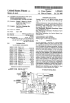
FIG. 1 is an overall system block diagram illustrating
the principles of the present invention.
FIG. 2 is an enlarged and diagrammatic plan view of
having a series of equally closely spaced microscopic
radial lines, and an integrated circuit photo sensitive
reticle-masked diode array 36, which in combination
single servo sector pattern for inner and outer tracks, 10 produce the light and dark polyphase (e.g. quadrature)
a wedge shaped portion of the rigid disk, illustrating the
patterns depicted in FIG. 6 and are used to generate the
sawtooth servo waveform A depicted in FIG. 7.
There are ?ve outputs from the photo sensitive array
36. Four of the outputs are quadrature track position
with the middle tracks broken away to save drawing
space.
FIG. 3 consisting of graphs A-L is a series of timing
and waveform diagrams related to the operation of the
system in response to sensing the track servo sector
signals which are processed by the differential ampli?
information depicted in FIG.’ 2.
ers 38 and 40. The ?fth is a signal which indicates loca
tion of the heads 30 at track zero (i.e. the radially outer
most useable data track) and it is ampli?ed and shaped
FIG. 4 is a block and schematic diagram of some of
the circuitry of the system depicted in FIG. 1.
FIG. Sis an enlarged sectional view in side elevation
of the coarse head position sensor assembly of the sys
tem depicted in FIG. 1.
FIG. 6, consisting of graphs A-D, is a series of
graphic representations of the operational states of the
sensor assembly depicted in FIG. 5.
FIG. 7, consisting of graphs A-L, are waveform
diagrams depicting the control signals generated by the
FIG. 1 system in response to the FIG. 5 sensor.
by an ampli?er 42. The quadrature signals from the
differential ampli?ers 38 and 40 are supplied to a posi
tion linearity switch detector circuit 44 which provides
the waveforms B and C depicted in FIG. 7, and also to
a position signal selector circuit 46, the operation of
which is controlled by the switch detector circuit 44.
25
As depicted diagrammatically in FIG. 1, structurally
in FIG. 5, optically in FIG. 6 and electrically in FIG. 7,
the scale 34 rotates with the head structure 28 relative
to the frame 100. With this rotation the scale microlines
FIG. 8 is a waveform diagram depicting operation of
pass between and interrupt the light beams passing from
the system of FIG. 1 during a track seeking operation of 30 the
light source 32 to the detector array 36. With the
approximately 120 tracks in radial distance.
geometry of the detector array being in accordance
FIG. 9 is a somewhat diagrammatic view in side
with the FIG. 6 sketches, four data tracks may be de
elevation and vertical section of a disk drive and head
?ned by each microline and space.
carriage assembly in accordance with principles of the
The geometry of the light sensitive photodiode array
present invention.
35 36 is depicted in FIG. 6. Actually, there are four pairs of
detector windows which are radially offset by a dis
DESCRIPTION
PREFERRED EMBODIMENT
tance of a half of a microline. Each window pair sees
Referring to FIG. 1, the hard disk memory system 10
four phases of each line: ?rst half line, full line (full
illustrated in overview therein is one in which a drive
dark), last half line, and no line (full light). The window
spindle 12 and one to four approximately eight inch 40 pairs are further paired together diagonally. For exam
diameter magnetic disks (two disks 14 and 16 are de
ple, the top left window pair and the bottom right win
picted) are caused to rotate about the common axis of
dow pair provide the two differential inputs to the am
the spindle at e.g. 50 Hz (3000 RPM) by a suitable disk
pli?er 38, and the bottom left and top right pairs are the
drive motor 18 with pulleys and a drive belt 20 in con
inputs to the ampli?er 40. In FIG. 6A equal and oppo
ventional fashion, The system 10 may include as many 45 sitely phased light and dark areas in the upper left and
as four or more magnetic disks, and other disk diameters
lower right detector parts provide a null output de?n
such as fourteen or ?ve and one quarter inches are
useable, although eight inches is presently preferred.
ing one track. In FIG. 6B the scale 34 has moved to the
next phase so that full lines are now seen in the top left
The disks 14 and 16 may be formed from thin aluminum
windows. In this situation the bottom left and top right
sheet having an oriented ferric oxide or other suitable 50 are equal and opposite, and the ampli?er 40 is at null
magnetic coating on the major surfaces thereof. While
point de?ning the next data track. In FIG. 6C the scale
magnetic surface disks are described, the present inven
34 has moved yet another half line width and the third
tion may be effectively utilized with other kinds of data
phase pattern presented is the same as FIG. 6A, except
storage devices, including laser etched disks or optical
for phase reversal In FIG. 6D the scale 34 has moved
storage devices. An index marker 22 provided on the 55 still another half line width to the fourth phase pattern,
spindle (F ‘IG. 9) is used to provide a tachometer or
similar to the FIG. 6B pattern, except for phase rever
index clock signal which is used to control servo opera
sal.
tions in a manner to be described shortly and which also
The output of the position linearity switch detector
serves as a check to assure that the disks are rotating at
44 is depicted as the FIG. 7 B and C waveforms. The
the desired 50 Hz angular velocity.
A head carriage assembly 24 includes a pure-torque
generating rotary actuator 26 to which head support
beams 28 are mounted for radial movement relative to
the disks 14 and 16. The rotary actuator 26 is described
output from the position signal selector 46 is an analog
value which is supplied to a summing network 48, and
then on through a loop compensation (damping) net
work 50, a bidirectional moving coil driver ampli?er
circuit 52 and ultimately to the armature coils of the
in greater detailed in the incorporated and referenced 65 rotary actuator 26 via a bidirectional rotation driving
prior US. Pat. No. 4,490,635. Read/write transducers
line 54. The analog value produces a correction torque
(heads) 30 are secured to the periphery of the support
to keep the heads 30 within the boundaries of each data
beams 28, and these heads may be of the type which ride
track de?ned by the scale 34 and photodetector 36. The
7
4,920,434
light emitting diode light source 34 is powered by a
8
It will be appreciated by inspection of FIG. 2 that
driver circuit 56 which includes an automatic light level
servo bursts on innermost tracks n-3, n-2, n-1 and n are
(AGC) control developed from a sixth photodetector in
much smaller in amplitude than bursts on outermost
the detector array 36.
The data read by one of the transducers 30 is selected,
tracks 00, 01, 02, 03 and 04. Consequently, in order to
calculate a valid offset signal for ?ne position servo
purposes, it is'necessary to calculate the percentage of
difference between burst amplitudes with the micro
preampli?ed and low pass ?ltered by the circuits de
noted by the block 58 of FIG. 1. Thereafter, the repro
duced MFM formatted data is recovered by a data
recovery circuit 60 and sent to the host computer or
processor 76. This calculation automatically provides
an automatic gain control (AGC) signal for each track,
other appliance to which the system 10 is connected for 0 a signal which may be applied to the data recovery
circuit 60 or to other circuits for providing gain equal
random access data storage and retrieval.
ization
for recovered data.
One disk surface 14 may be provided with a narrow,
A disk drive interface circuit 88 receives control
200 byte wide sector 62, which is depicted diagramati
information from the host computer, etc., and supplies
cally in FIG. 2 and electrically by the FIG. 3 wave
that information, including track seek data to the micro
forms. Each data track, from track zero zero to track n
processor 76. Data surface/head select information is
(e.g. track 511) is provided with two factory prere
sent directly to the head select circuit 58. The micro
corded frequency bursts, a ?rst occurring burst B1 on
processor 76 always knows where the head is presently
the outside half of e.g. odd tracks (and inside half of e. g.
located because of a two bit quadrature signal line from
.even tracks) and a second occurring burst B2 on the
the switch detector 44. The microprocessor 76 deter
inside half of odd tracks (outside half of even tracks).
mines
how far and in what direction to move the head
The sector bursts are read each revolution by the head
30 and are used to provide a ?ne head position servo
(seek) and then it calculates a set of numbers which are
put out in a sequence dependent upon actual head posi
loop control signal to the rotary actuator 26 in the form
tion sensed at the optical encoder 24 during the seek
of an offset voltage to urge the head 30 into alignment
25 operation.
with the centerline of the track. Each burst is read in
Some of the major elements of the coarse position
turn and integrated by the peak detector 66 to prove the
closed loop servo and the digital override circuitry are
amplitudes thereof. These amplitudes are then sampled
depicted in FIG. 4. Therein, the latch 84 is depicted as
and held by circuits 68 and 70. The held values are
a standard TTL type 74LS374 latch which is clocked
selected by an analog data selector 72 and converted to
by an input from the WRITE line of the microprocessor
eight bit digital value by an analog to digital converter
76. The digital to analog converter (DAC) 86 is de
74. The digital values are processed in a digital system
picted as a Motorola type MC 1408L8, and it receives
controller microprocessor 76, such as the Intel type
the latched eight bit numbers of offset values from the
8048 which contains a 1k byte factory preprogrammed
latch 84 and converts them to control currents. A volt
read only program memory and a 128 byte random 35 age reference circuit 102 is utilized to reference the
access scratchpad memory.
DAC to system voltages. An operational ampli?er cur
A detector 78 detects the index mark on the drive
rent to voltage converter 106 buffers and scales the
spindle 12 with each revolution. This index clock signal
resultant analog control voltage from the DAC 86. The
is passed through an ampli?er 80 and sent to the micro
summing circuit 48 in the implementation depicted in
processor 76 to provide a digital tachometer to deter
FIG. 4 occurs at the input of the driving ampli?er 52
mine whether the disks are rotating at correct speed and
which is supplied with the analog offset voltages from
to mark the location in time of the servo sector on the
the DAC 86 and the coarse servo loop selected analog
disk. The index clock is alsolprocessed by a servo sam
phase from the position signal selector 46.
ple timer 82 which is used to enable and switch between
The circuitry of the bidirectional driving ampli?er 52
the sample and hold circuits 68 and 70.
emulates the operation of a differential output ampli?er.
The waveforms of FIG. 3 illustrate the operation of
To do this, the circuitry includes two ampli?ers 108 and
the circuit elements 30, 58, 64, 66, 68, 70, 72, 74, 76, 78,
110 wired as shown in FIG. 4. The analog controls to
80 and 82 which provide the ?ne position servo. Wave
the driving ampli?er 52 occur at the input of the op amp
form A depicts the 50 Hz index pulse I generated from
108, and the digital seek override controls are applied
the index marker 22 by the index detector 78. Wave
directly to the inputs of two Darlington pair power
forms B and C depict the ?rst occurring Burst 1 and
drivers 112 and 114 which drive the two windings A-B
second occurring Burst 2. Waveform D depicts the
and B-C of the rotary actuator The op amp 110 func
servo sector data window which immediately follows
tions to make the characteristics of the driver 114 oppo- ‘
each index pulse. Waveform E shows the control signal
site and complementary to the input of the driver 112.
from the servo sample‘ timer 82 as it is applied to the 55
An operational ampli?er 116 receives two comple
sample and hold circuits 68 and 70. It divides the sector
mentary coarse servo loop analog phase control signals
into two 100 byte halves Waveform F shows the ampli
P and bar P from the position signal selector 46. These
tude of a ?rst burst A stored in the ?rst sample and hold
values are equal and opposite and are of minimum am
circuit 68. Waveform G shows the amplitude of the
plitude when the head carriage 28 is in general align
second burst B stored in the second sample and hold
ment with any given de?ned track. The P and Bar P
circuit 70. Waveform H depicts equivalence of sensed
values are selected by the position signal selector 46 in
amplitudes which‘ obtains when the head is properly
accordance with the digital quadrature waveforms K
aligned within one data track. In this situation no offset
and L depicted in FIG. 7.
value is required and none will be supplied by the mi
>
An accelerate and decelerate combinatorial logic
croprocesor 76 to the rotary actuator 26. Waveform I 65 array 118 accepts a two bit word derived from the high
depicts a much larger ?rst burst than second burst
order data bit clocked from the latch 84, and a binary
which indicates that the head 30 is not on center but is
control line from the microprocessor 76 designated the
close to an edge of the track.
SEEK ENABLE line. The logic 118 provides digital
4,920,434
10
implementation of this mode is to select the appropriate
monophase of the quadrature signal and servo over its
full cycle (i.e. a distance of plus or minus two tracks). In
outputs which are buffered and inverted and are then
applied to the input of the power ampli?er 112 via a line
120 and to the inverted input of the ampli?er 114 via a
line 122 (and the inverting op amp 110). The power
ampli?ers 112 and 114 may be implemented as type TIP
this way the radial range of servo loop control covers a
full four tracks, and only in the event that the'head
structure 28 is signi?cantly jarred or otherwise is exter
nally caused to move beyond plus or minus two tracks,
140 power Darlington pairs which are thermally
sumped to the cast aluminum frame 100 (FIG. 9) of the
system 10. The operational ampli?ers 106, 108, 110 and
116 may be type 741, or equivalent.
A power supply switch 124 switches on the power
will the coarse servo lose control. Upon a loss of servo
control the system 10 enters a reset mode which resets
ence of the required supply voltages, a READY control
the system and returns the head 30 to the last selected
track.
The microprocessor 76 has essentially ?ve modes or
operation or tasks: initialization, ?ne servo offset super
signal from the microprocessor 76, which denotes that
vision, track seeking, emulation of other disk drive
supply to the ampli?er 52 only when it concurrently
receives three enabling signals a signal indicating pres
the disks 14, 16 are spinning at operating velocity, and a 15 products, and self diagnostics. In the initialization or
DRIVE INHIBIT line signal In the event of a loss of
start up mode when power is ?rst applied, the micro
operating velocity, power supply potential or in case of
processor 76 counts index pulses and compares them
a system reset, power is removed from the driver ampli
with an internal clock, to be sure that the disk spindle 12
?er 52, and the head carriage assembly 28 automatically
is rotating at the proper velocity (50 Hz) The head 30 is
returns to the inner landing zone in response to a bias 20 initially located in a nonabrasive landing zone L (FIG.
spring 194 (FIG. 9) which operates in default of the
2). The microprocessor 76 initially'commands a seek to
the outermost track (track 00). When the head 30
The individual circuit components depicted in FIG. 4
reaches the outermost track, a special output is obtained
are connected as shown and will not be discussed fur
from the transducer 24 through the ampli?er 42 (FIG.
ther, since the values and connections are readily de 25 7-J). The microprocessor 76 then calibrates the ?ne
rived by those skilled in the art.
servo by measuring, establishing and remembering off
Referring to FIG. 1, an eight bit data word output
sets for the four outermost tracks 00, 01, 02, and 03, and
from the microprocessor 76 is supplied to the data latch
then for the four innermost tracks n-3, n-2, n-1 and 11. If
84 which is clocked by the WRITE ENABLE line of
there is any difference in initial calibration between the
the microprocessor 76. Each eight bit number held in 30 outermost and innermost tracks, the microprocessor 76
the latch 84 is converted to an analog value by the
spreads this difference e. g. linearly over the total num
digital to analog converter86. The high order latched
ber of tracks of the system. The microprocessor 76 then
bit, along with another control line direct from the
commands the head 30 back to track 00. Initialization is
rotary actuator 26.
microprocessor 76, is applied directly to the driving
ampli?er 52 so as to override the coarse position servo 35
system (elements 24, 38, 40, 44, 46, 48, 50) during the
then complete.
During read and write operations, the microproces
maximum accelerative and decelerative phases of a
track seek operation. In the final phase of a track seek,
sor 76 reads the ?ne servo continuously and updates the
offset, to take into account position errors such as ther
mal expansion of the disks 14, 16 as internal ambient
a predetermined velocity slewing rate is achieved by
temperatures rise.
recurrent number series which are converted to analog 40
values by the converter 86 and applied to the summing
circuit 48. During the initial maximum accelerative and
seek commands digitally from the host computer via the
disk drive interface 88. The microprocessor 76 main
tains head position data in a register which counts the
tracks from information derived from the coarse posi
decelerative step function portion, the coarse servo
loop is completely overriden. At about eight tracks
from the destination track, the maximum deceleration
command is removed just before the carriage assembly
»
As already explained, the microprocessor 76 receives
45
tion transducer 24. The difference between the track at
which the head is presently located and the track
24 ceases to move. Thereafter, the coarse servo is com
sought, together with the sign value of the difference,
manded to slew across each’ track by a progressive
analog staircase signal which is reset to zero with each
detected track crossing. In this way, the coarse servo,
which indicates the direction of head movement re
under the command of the microprocessor 76, operates
solely upon the position information derived from the
transducer 24 and irrespective of actual instantaneous
velocity of the rotary actuator 26.
quired to accomplish the seek, is used to calculate the
series of commands from the microprocessor 76 to the
rotary actuator 26.
'
-
The emulation function of the microprocessor 76
enables the system 10 to emulate the characteristics of
other disk drives. One such emulation would be of the
If a track crossing occurs sooner than expected, then 55 SA 1000 eight inch disk drive manufactured by Shugart
the staircase command resets to zero before a maximum
value is reached. If a track crossing is delayed, then the
staircase reaches and holds its maximum value until the
transition. These conditions are illustrated in FIG. 8A.
Finally, a short deceleration step function may be
applied to stop the carriage assembly 24 at the destina
tion track should its velocity not then have reached
zero. FIG. 8A depicts the digital and analog waveforms
Associates, a Xerox Corporation subsidiary located in
Sunnyvale, Calif. The SA 1000 product utilizes two
adjacent read/write heads, and the microprocessor 76
enables the system 10 to appear to a user as if two heads
are actually physically present in the system. This emu-
lation is readily provided by rede?ning the track count
ing structure in the microprocessor 76 into two series of
interleaved odd and even tracks, and then reading odd
utilized to command a track seek across e.g 120 tracks.
tracks as though it were with vone of the heads, and
FIG. 8B portrays the velocity of the head carriage 65 reading even tracks as though it were with the other of
relative to radial distance across the 120 tracks.
the heads Other competitive disk drive equipment may
When the destination track has been reached, the
be emulated by special programming of the micro
system 10 enters a track extension control mode. One
processor 76.
4,920,434
11
12
The self diagnosis function of the microprocessor 76
has short term and long term aspects. During operation,
the microprocessor 76 constantly monitors disk rotating
of coil windings in the coil assembly 174 There are e. g.
six coil windings, as there are, e. g six magnetic segments
in the magnet 176. An annular ?ux return plate 178 of
low carbon steel forms a base for the magnet 176. In
fabrication, a ceramic blank is glued to the base plate
178 and then the resultant structure is permanently
magnetized. A ?xed shaft 180 extends from a ribbed
portion of the frame 100. The hub 172 is journalled to
the shaft by ball bearing assemblies 182 and 184 which
=
speed and head position In the event of a discrepancy in
either parameter, the microprocessor 7.6 takes the disk
out of service and informs the host machinery of the
detection of an error. Other errors and error messages
are easily included, including those particularly adapted
to a data format or end use. Diagnostic routines may be
contained in .the read only memory of the microproces
sor 76 or they may be recorded on one or more of the
tracks of the disk 14, and called by the microprocessor
76 as required.
Referring now to FIG. 5, the coarse head position
servo transducer 24 is depicted in enlarged structural
side elevation and vertical cross section. The transducer
24 is a U-shaped assembly comprising an upper member
132 which supports the photodetector and reticle array
36, and a lower member 134 which is keyed to hold the
LED light source 32 in vertical alignment with the 20
photodetector 36. The scale 34 is a glass member having
are initially held in place during fabrication by an axial
preload spring 186, and spacer 188, with adhesive lock
ing the bearings 182, 184 to the hub 172.
A ?ux return top plate 192 is secured to the frame
100. A bias spring 194 extends from a standoff on the
top plate 192 to the head carriage assembly 28 and bi
ases it to return to the inner landing zone of the disks
when power is removed from the rotary actuator 26.
Crash stops may be formed in the top plate 192 to limit
range of head structure travel.
Other elements depicted in FIG. 9 include a printed
circuit board 196 which carries the circuitry immedi
equally spaced apart chrome microlines deposited
ately associated with the optical transducer 24 including
the elements 38, 40, 42 and 56 depicted in FIG. 1 and
support structure 28 e g. at the rotary actuator 26 The
also the wiring connection of the heads 30. A main
transducer 24 is mounted on a post 136 embedded in the 25 printed circuit board 198 carrying the rest of the cir
cast aluminum frame 100 which securely supports all .of
cuitry of FIG. 1 is plugged into the board 196 at a plug
the disk drive machinery.
200. A plastic case 202 mates with the base 100 and
A feature of the present invention is that the trans
provides an airtight seal throughout which is required
ducer 24 is adjustable in two dimensions with. but one
for the reliable operation of ?ying head Winchester
point of attachment to the frame 100. A vertical height
drive technology. An air filter 203 ?ts into a recess of
setting screw 138 and lock Washer 140 enables the
the frame and ?ns 204 extending from the ?ange at the
members 132 and 134 to be adjusted up and down, so
base of the spindle 12 force air within the plastic enclo
that the photodetector can be adjusted to within ?ve
sure 202 to pass through the ?lter 203. A breather ?lter
thousandths of an inch of the scale 34 to achieve the
206 enables internal and external pressures to equalize.
required resolution A spring 142 biases the members 132
Counterweights, not shown, are added to the hub 172
thereon. It is precisely and securely attached to the head
and 134 away from the frame 100.
to place the center of mass of the head structure 28 in
Sideways alignment of the transducer 24 with respect
alignment with the axis of rotation of the rotary actua
to the scale 34 is achieved by rotating the members 132
and 134 about the axis of the post 136. A locking screw
mechanism 144 locks the members 132 and 134 to the
tor 26. In this way, no unbalanced forces pass through
the rotor bearings 182 and 184 as the actuator rotates
about its axis.
It will be apparent to those skilled in the art that the
post 136 at the desired sideways alignment.
The structural con?guration of the system 10 is de
picted in FIG. 9. Therein, the drive hub 12 supports
present invention may be embodied physically in a wide
variety of ways and with many different elements and
four disks, a top servo sector containing disk 14 and
components. For example, the optical transducer 24
three lower disks 16. The index detector 22 is provided 45 may be implemented magnetically. Alternatively, trans
in a lower outer ?ange of the spindle 12, and the sensor
ducer information may be provided in the servo sector
78 is secured through the frame 100. The spindle 12 is
62 and read with each rotation of the disk 14. The ro
mounted to a spindle shaft 152 by a screw 154 and a
tary actuator 26 may be replaced with an electrical
washer 156. Ball bearing assemblies 158, 160 are placed
detent, microstep providing stepping motor, and the
in a cylindrical portion of the frame 100 and are held in
combination of such a stepping motor with the time
a spaced apart con?guration by a spring 162. A mag
sampled ?ne servo loop will vastly improve track cen
netic ?uid seal 164 is placed above the bearing 158 and
terline following performance in a disk drive. The servo
seals the bearings by magnetic cohesion of the sealing
loop systems of the present invention are advanta
?uid. A bottom screw 166 secures a pulley, not illus
geously, but not necessarily embodied in rotating mag
trated, to the shaft for the drive belt 20 from the motor
netic disk storage devices.
18.
Having thus described an embodiment of the inven
The rotary actuator 26 is depicted in FIG. 9. In the
tion, it will now be appreciated that the objects of the
FIG. 9 vertical cross section, the rotary actuator 26
invention have been fully achieved, and it will be under
includes a hub 172 to which the head structure assembly
stood by those skilled in the art that many changes in
28 is mounted. A ?at coil assembly 174 is secured by a 60 construction and widely differing embodiments and
holding means such as adhesive to the base of the hub
applications of the invention will suggest themselves
172. Immediately below the coil assembly 174 is a fer
without departure from the spirit and scope of the in
roceramic permanent magnet 176 which is fabricated as
vention. The disclosures and the description herein are
a unitary structure and then magnetized into a series of
purely illustrative and are not intended to be in any
adjacent even-number opposed ?eld magnetic segments 65 sense limiting.
in which the north and south poles alternate at the top
We claim:
and bottom of the magnet 176. The number of separate
1. A disk drive for increasing the density or concen
segments in the magnet 176 corresponds to the number
tric storage tracks on a data storage surface of a rotating
4,920,434
13
14
data storage disk without requiring a disk servo surface,
the two part structure is adjustably mounted to the
the disk drive comprising:
housing.
3. The disk drive set forth in claim 2 wherein the one
of the said two part structure comprises a radial micro
an enclosed housing,
at least one disk'rotatably mounted within the hous
mg,
each such disk having concentric data storage tracks
on each surface thereof,
line scale having a series of equally closely spaced mi
croscopic radial lines, and the other one of the two part
structure comprises an assembly including a light
source, a lens, a reticle mask and photodetector array
'
motor means for rotating the disk at a predetermined
means for putting out the plural cyclical signals there
angular velocity,
being a transverse gap between the lens and the reticle
mask through_ which the scale arcuately moves as the
at least one data head for reading and writing user
data from and to each data storage surface while
rotary actuator structure rotates.
4. The disk drive set forth in claim 3 wherein the
?ying in close proximity thereto,
a mass balanced electromechanical rotary actuator
photodetector array means includes four cells for gener
structure mounted within the housing, the data
head being mounted on and positioned by the ro
tary actuator structure,
ating the plural phase cyclical~signals in quadrature.
5. The disk drive set forth in claim 3 comprising a
'
translucent region of the scale extending throughout its
an optical polyphase head position transducer cou
pled closely to the rotary actuator structure and
range of arcuate movement and an AGC photodetector
cell within the photodetector array means cooperating
with the translucent region of the scale, the disk drive
comprising automatic gain control means including the
the housing for generating plural phase cyclical
signals in quadrature, a selected one of the phase
signals providing a servo reference for track fol
AGC photodetector cell for regulating the intensity of
lowing, -at least four adjacent storage track loca
light energy put out by the light source.
tions being included within a range of movement of
the actuator structure relative to the housing and
6. The disk drive set forth in claim 3 comprising a
track zero region of the scale located at one end of its
range of arcuate movement and a track zero photode
disk within one cycle of one of the plural phases,
position linearity switch detector means connected to
tector cell within the photodetector array means, the
track zero photodetector cell being connected to ampli
the optical polyphase head position transducer for
generating storage track location signals from the
plural phase signals,
position signal selector means connected to the opti
cal polyphase head position transducer and the
position linearity switch detector means for select
.ing one of the phase signals as the servo reference
corresponding to a selected storage track location
?er means for providing an electrical track zero signal
30 to the controller means.
for track following,
track seeking means which includes controller means
and bidirectional driving ampli?er means and
which is responsive to the location signals, for
controlling the actuator structure to move the data 40
head to selected storage track locations,
at least one storage surface being recorded with head
position correction information which is readable
by the data head,
.
7. The disk drive set forth in claim 4 wherein the four
photodetector cells for providing the quadrature phase
signals are arranged in two rows of two cells each, each
rod having a different radial centerline with respect to a
center of rotation of the rotary actuator than the other,
the two cells of one row each being diagonally arrayed
with a cell of the other row, the diagonally arrayed cell
pairs being connected to two differential ampli?er
means for providing the phase signals in quadrature.
8. The disk drive set forth in claim 1 wherein the head
position correction information is recorded in at least
one region wherein the head position correction infor
mation is included within two adjacent data storage
track locations, the data storage track locations lying
the controller means comprising: (a) means for caus 45 within the range of movement of the actuator structure
ing the data head to read the correction informa
tion, (b) means for processing the correction infor
mation, and (c) means for putting out a correction
value for the selected storage track location for
track following,
a head positioner circuit including summing junction
means for combining the selected one of the phase
signals from the position signal selector means and
the correction value from the controller means to
produce a position signal, and further including the
bidirectional driving amplifier means for driving
the electromechanical rotary actuator structure in
response to the position signal during track follow
ing,
within the said one cycle of one of the plural phases of
the plural phase cyclical signals.
9. The disk drive set forth in claim 8 wherein the at
least one region comprises four adjacent data storage
tracks.
10. The disk drive set forth in claim 9 comprising two
said regions including the correction information; a ?rst
region at a radially outermost portion of the storage
surface accessible by the data head, and a second region
at a radially innermost portion of the storage surface
accessible by the data head.
11. The disk drive set forth in claim 1 wherein the
head position correction information is recorded in a
sector within a plurality of storage track locations on
interface means for providing data selection informa 60 the storage surface.
tion from a host computing system for transferring
12. The disk drive set forth in claim 11 wherein the
data between the host computing system and the
plurality of storage track locations includes four radi
data storage surface via the data head.
ally outermost adjacent storage track locations of the
2. The disk drive set forth in claim 1 wherein the
storage surface.
optical polyphase head position transducer comprises a 65 13. The disk drive set forth in claim 11 wherein the
two part structure, and wherein one of the parts of the
plurality of storage track locations includes each 'con
two part structure is mounted directly to the mass bal
centric data storage track location de?ned on the stor
anced rotary actuator and the other one of the parts of
age surface.
4,920,434
.
16
15
14. The disk drive set forth in claim 11 wherein for
each storage track location the sector includes two
radially offset bursts, a ?rst occurring burst and a sec
the upper ?ux return plate or lower ?ux return plate,
there being a gap between the upper ?ux return plate
and the lower ?ux return plate, and coil means forming
ond occurring burst, the bursts being radially offset
oppositely from the storage track location centerline,
a part of the rotary actuator structure mounted for
movement within the gap so that current applied to the
and wherein the controller means includes peak detec
tor means for detecting the peak amplitude of each burst
read by the data head, ?rst sample and hold circuit
means for sampling and holding the peak amplitude of
the ?rst occurring-burst, second sample and hold circuit
means for sampling and holding the peak amplitude of
coil means by the bidirectional driving ampli?er means
causes the actuator structure to be controllably dis
placed to move the data head among the concentric
data storage track locations on the storage surface.
25. A ?xed disk drive for increasing the density of
concentric storage tracks on data storage surfaces of a
plurality of rotating data storage disks without requir
the second occurring burst, servo sample timer means
responsive to spindle marker means marking the loca
ing a disk servo surface, the disk drive comprising;
tion in time of the sector for controlling the ?rst and
an enclosed housing;
a plurality of data storage disks commonly mounted
second sample and hold circuits, and selector means for 15
processing the peak amplitude samples from the ?rst
for rotation within the housing and each including
and second sample and hold means.
two data storage surfaces;
15. The disk drive set forth in claim 1 wherein the
position signal selector means is connected to maintain
selection of the said one of the phase signals as the servo
reference over the full cycle of the selected phase signal
so that disk drive has a servo loop range covering four
adjacent storage track locations.
16. The disk drive set forth in claim 1 wherein the
controller means includes programmed digital micro 25
processor means and analog to digital converter means
for converting into digital values the head position cor
rection information read by the data head, and latched
digital to analog converter means for receiving, latch
ing and converting to an analog value the correction
value during track following.
17. The disk drive set forth in claim 1 wherein the
head positioner circuit further comprises a servo loop
motor means for rotating the disks at a predetermined
angular velocity;
a plurality of data heads, there being one data head
for each data storage surface of each disk for read
ing and writing user data from and to each data
storage surface while flying in close proximity
thereto;
read preampli?er means switchably connected to
each of the data heads;
data recovery circuit means connected to the read
preampli?er means for recovery data read by a
selected data head;
selection circuit means for selecting a data head;
a mass balanced electromechanical rotary actuator~
structure rotatably journalled within the housing,
18. The disk drive set forth in claim 1 comprising a
the data heads being commonly mounted on and
commonly positioned by arcuate movement of the
rotary actuator structure;
head positioner circuit means including:
plurality of data storage disks rotatably mounted within
phase-quadrature-providing head position optical
the housing on a single disk spindle means, and a plural
ity of data heads, there being at least one data head
associated with at least one data storage surface of each
disk.
19. The disk drive set forth in claim 18 further com
prising head select means for selecting one of said data
transducer means coupled closely between the
rotary actuator and the housing for generating
plural phase cyclical signals, a selected one of the
plural phase cyclical signals providing a servo ref
phase compensation network between the summing
junction and the bidirectional driving ampli?er means.
heads for read/write operations during track following.
20. The disk drive set forth in claim 1 further com 45
erence for track following, at least four adjacent
data storage track locations included within a
range of arcuate movement of the rotary actuator
relative to the housing and disk within one cycle of
prising preampli?er- means connected to the data head
one of the plural phase cyclical signals,
and data recovery circuit means connected to the read
position linearity switch detector means connected
to the head position optical transducer means for
preampli?er means for recovery data read by the data
head.
21. The disk drive set forth in claim 16 further com
prising preampli?er means connected to the data head
and data recovery circuit means connected to the read
generating location signals from the plural phase
cyclical signals to indicate nominal data storage
track locations,
.
croprocessor means for transferring data from the stor
position signal selector means connected to the
head position optical transducer means and the
position linearity switch detector means for se
age surface to the programmed digital microprocessor
lecting one of the plural phase cyclical signals as
preampli?er means and to the programmed digital mi
means.
22. The disk drive set forth in claim 21 wherein the
data transferred means includes disk drive diagnostic
routines for execution by the programmed digital mi
croprocessor means.
23. The disk drive set forth in claim 16 wherein the
programmed digital microprocessor means comprises a
single programmed microprocessor integrated circuit.
24. The disk drive set‘forth in claim l'wherein the
mass balanced electromechanical rotary actuator struc 65
ture includes a ?xed assembly mounted to the housing
including an upper flux return plate, a lower flux return
plate, and a permanent magnet affixed to at least one of
the servo reference corresponding to a selected
storage track location for track following,
head position correction information prerecorded
on at least one of the data storage surfaces readi
ble by the data head associated with the said at
least one data storage surface,
analog to digital converter means for converting
samples of the head position correction informa
tion into digital position error values,
digital processor means programmed for selecting
via the selection circuit means the data head
associated with the said at least one data storage
surface to read the head position correction in
4,920,434
17
formation, for receiving the digital position error
values, for processing the digital position error
18
within the gap so that current applied to the coil means
by the bidirectional driving ampli?er means causes the
values and for providing a correction value for
rotary actuator structure to be controllably rotated
selected data storage track locations during track
about an arc of limited rotational displacement to move
following operations of the disk drive, the digital
5 the data heads among all of the available concentric
processor means being further programmed for
data storage track locations on the storage surfaces.
27. The disk drive set forth in claim 25 wherein the
head position correction information prerecorded on at
least one of the data storage surfaces comprises informa
carrying out track seeking operations of the disk
drive in response to data location selection infor
mation and in response to the head position opti
cal transducer means by generating seek values
latch means for latching the correction values dur
tion contained in a sector on the said at least one data
storage surface.
28. The disk drive set forth in claim 27 wherein for
ing track following operations,
digital to analog converter means for converting
the latched correction values to analog correc
tion values,
.
15
summing junction means for combining the se
lected one of the plural phase cyclical signals
from the position signal selector means and the
ond occurring burst, the bursts being radially offset
oppositely from the data storage track centerline, and
wherein the head positioner circuit further includes
analog correction values during track following
operations to produce a corrected position sig
nal, and
bidirectional driving ampli?er means for driving
each data storage track location the sector includes two
radially offset bursts, a ?rst occurring burst and a sec
20
peak detector means for detecting the peak amplitude of
each burst read by the data head, ?rst sample and hold
circuit means for sampling and holding the peak ampli
tude of the second occurring burst, servo sample timer
means responsive to spindle marker means for control
the rotary actuator in response to the corrected
ling the ?rst and second sample and hold circuits, and
and for driving the rotary actuator in response to 25 selector means for processing the samples from the ?rst
and second sample and hold means for the analog to
the seek values during track seeking operations;
digital converter means.
and,
position signal during track following operations
29. The disk set forth in claim 25 wherein the head
position correction information is recorded in at least
for transferring data between the host computing 30 one region wherein the head position correction infor
mation is included within two adjacent data storage
system and a selected data storage surface via the
track locations, the data storage track locations lying
data head associated with the selected storage
within the range of movement of the rotary actuator
surface.
interface means for providing data location selec
tion information from a host computing system
structure within the said one cycle of one of the plural
26. The disk drive set forth in claim 25 wherein the
rotary actuator structure includes a ?xed assembly 35 phases of the plural phase cyclical signals.
30. The disk drive set forth in claim 29 comprising
mounted to the housing having an upper flux return
two said regions, a first region at a radially outermost
plate a lower flux return plate, and a permanent magnet
portion of the storage surface accessible by the data
affixed to at least one of the upper ?ux return plate or
head associated with said storage surface, and a second
the lower flux return plate, there being a gap de?ned
between the upper ?ux return plate and the lower ?ux 40 region at a radially innermost portion of the said storage
surface accessible by the said data head.
return plate, and coil means forming a part of the rotary
*
actuator structure and mounted for arcuate movement
50
55
60
65
*
*
*
*