1
MT9750 V5.0
(MS Windows 95, MS Windows NT)
9750 Emulation under Windows
Product Manual
Edition February 1998
Copyright and Trademarks
Copyright © Siemens Nixdorf Informationssysteme AG 1998.
All rights reserved.
Delivery subject to availability; right of technical modifications reserved.
All hardware and software names used are trademarks of their respective manufacturers.
Preface
General information on MT9750
The MT9750 functions
Hardware and software requirements
Installation
Configuration
Working in emulation sessions
Printing
The diagnostic file
The keyboard
Continued
Character sets, compose characters, and printer
control characters
Appendix
Glossary
Abbreviations
Related publications
Index
1
Preface
This product manual describes the MT9750 V5.0 emulation program from
Siemens Nixdorf Informationssysteme AG (SNI). This chapter deals with the following subjects:
– The basic functions of MT9750 and improvements to the preceding version
– Guidelines on the use of this manual
– Overview of the individual chapters
– The notational conventions used in this manual
1.1
Brief description of the product MT9750
MT9750 V5.0 is a terminal emulation program that can be used under MS® Windows® NT 4.0 and MS Windows 95 as a true 32-bit application. MT9750 emulates the functions of a data display terminal on your PC (in the BS2000® environment, terminals are called data display terminals). With the exception of only
slight differences, it simulates the functions of a 9763 data display terminal and
when configured appropriately it can emulate another terminal from the 9750
product family. The appearance can be adapted to suit your individual requirements regardless of the functions emulated. The term 9750 is used in this
manual as a generic term for data display terminals of type 9750, 9755, 9756,
9758, and 9763.
9750 data display terminals are connected to Siemens Nixdorf mainframes running the BS2000 operating system (BS2000 hosts). Using the emulation program, you can enter commands at your PC that are interpreted by the BS2000
host. In this way, your PC replaces a data display terminal and also offers the
diverse options associated with the modern PC world.
Product Manual
U42006-J-Z795-1-7600
Preface
1.2
Target group
Target group
This manual is intended for PC users who want to use the product MT9750 to
communicate with applications on a BS2000 host.
For a better understanding of this manual you should be experienced in using
a PC and know how a PC network operates. You also need to know how to use
the Windows interface as well as the relevant BS2000 applications. If you have
already worked with the functions of an actual DSS9750 data display terminal,
you will soon become familiar with MT9750.
If the emulation program MT9750 has already been configured for you, a knowledge of Windows and the basic BS2000 commands is sufficient to understand
the operating instructions for the emulation program.
The BS2000 environment (PDN, printers) must be configured by the BS2000
system administrator on the host or the communication computer (CC).
Product Manual
U42006-J-Z795-1-7600
Preface
1.3
Summary of contents
Summary of contents
This manual is divided into four parts that deal with various subjects relating to
each respective task.
In “Getting to know the product”, the functions of MT9750 are presented after
an introduction to the terminology. In addition to the connection options, the
9750 functions supported and the additional functions are described. Experienced PC users are provided with an overview of the programming boards supported by MT9750 for customizing and connecting to other PC applications.
The overview is followed by the part entitled “Preparing/configuring the product”
which describes the actions that must be performed before the program can be
used, i.e. installation and configuration of the emulation. Information on generating the host is required for setting up a connection correctly via the communication method to be used.
“Using the emulation” describes working with the emulation in the individual
sessions as well as how to use the additional emulation utilities efficiently. It also
contains information on problem diagnosis.
“Looking up information” contains information that is generally only required in
special cases.
The “Glossary”, “Abbreviations“ “Related publications”, and “Index“ chapters
are provided as a source of reference and are intended to help you as you work
through the manual.
Unless otherwise stated, MT9750 stands for version V5.0 of the MT9750 program in this manual.
Product Manual
U42006-J-Z795-1-7600
Preface
1.4
Changes since the last version of this manual
Changes since the last version of this
manual
The following section describes the new functions in MT9750 V5.0 compared
with V4.1.
●
MT9750 V5.0 now runs under Windows 95 as well as under Windows NT
4.0 as a 32-bit application.
●
A new, user-friendly installation program supports you in configuring the program on your PC.
●
Communication options:
– LAN connections via the Windows NT 4.0 or Windows 95 TCP/IP protocol stacks
– ISDN connection
– Telecommunications via the MODACOM mobile radio data network
– Telecommunications based on the GSM mobile telephone network
(D1/D2)
●
A user-friendly menu interface based on Windows 95.
●
Customization of keyboard mapping using a keyboard mapping program
●
Operating sequences are automated using the macro recorder, which
records user input, and editable macro files.
●
Other Windows applications can be started using macro keys.
●
Additional option for using programmable keys by adding user-defined P
keys - which are not overwritten by host applications - to the P keys concept.
●
A displayable window containing a user-defined selection of function keys
(hotspots) makes it easier to use the mouse.
Product Manual
U42006-J-Z795-1-7600
Preface
●
Print options:
–
–
–
–
–
●
Changes since the last version of this manual
Bypass printing in local area networks (LANs)
Choice between transparent print output and conversion with GDI print
Full-page hardcopy without cursor positioning
Bypass printing can be configured for transparent printing
Individual print filters can be connected
Extended options for exchanging data with other applications:
–
–
–
–
–
via the DDE interface
via a DDE API
via the EHLLAPI interface
via the Entire Connection interface
OLE automation
●
Compatibility with other SNI products for PC integration in BS2000 networks
(openFT, VFT, FHS-DOORS).
●
Additional country-specific variants and keyboards supported (e.g. Czech
and Greek language variants, trimodal keyboards, switching to alternative
character set in Cyrillic Windows).
●
XHCS/EHCS support.
●
Extended diagnostic facilities for troubleshooting.
●
The MTKonv conversion program allows you to continue to use existing connection and session configurations under MT9750 V5.0. It provides a simple
and user-friendly method of migrating from preceding versions.
Product Manual
U42006-J-Z795-1-7600
Preface
1.5
Notational conventions
Notational conventions
The following notational conventions are used in this manual:
italics
Names of files, programs, commands, variables,
options and screen dumps such as input fields,
text fields, menus etc. in the main body of the
text
bold
Syntax representations: constants
typewriter text
System output such as error messages, messages, notes, file excerpts
bold typewriter text
User input in examples
“quotes”
References to other chapters or manuals
Keys or key combinations in the main body of
the text
User actions
Ê
i
!
Product Manual
Additional information, notes, and tips
Warnings that must be observed
U42006-J-Z795-1-7600
Getting to know the product
2
General information on MT9750
This chapter introduces you to the fundamental concepts and terminology of
MT9750 emulation. It is intended for users with little or no previous knowledge
and can be read selectively.
You may want to skip this section if you have already worked with the preceding
version or similar products and are familiar with the terminology.
2.1
Terminal emulation
Host applications are generally operated at so-called terminals. The type of terminal depends on the host at which you are working; a BS2000 host terminal is
called a data display terminal for example.
A terminal emulation is a program that emulates the properties of a terminal on
another system. This means you can send data from this system (which would
not be suited to this without the emulation) to the host or receive data from the
host and access applications installed on a host. MT9750 is a terminal emulation that emulates the properties of a data display terminal on a PC. Using
MT9750, the users of a PC with Intel® processors 80486™ or higher (or processors compatible with these) can communicate with one or more BS2000 hosts.
MT9750 allows the connection of PCs in TCP/IP-based networks to BS2000
hosts. In this way, the range of functions of the host applications running centrally are available in full to the PC user running MT9750.
Product Manual
U42006-J-Z795-1-7600
General information on MT9750
2.2
Session
Session
A session is the logical connection of two programs for the purposes of
exchanging data. Session in this case refers to a connection between the
MT9750 emulation and a BS2000 application. The MT9750 session runs in a
window in Windows format. The data from the BS2000 host and keyboard input
is displayed in the window work area; this is the presentation area of the host.
Each session is allocated parameters which are saved under the session name
when the session is saved. These parameters relate to the connection configuration and also the configuration of the session display attributes (e.g. the size
of the characters displayed in the work area).
The session attributes are saved locally on your PC in a session file with the filename extension .MTS. In addition, the assignment of programmable keys is allocated to each session and is saved in a second file (with the filename extension
.MTK).
There are three special types of session and these are described below:
2.2.1
Temporary session
A temporary session is a session whose parameters are not saved, i.e. it is
only made available once. The connection is only required temporarily, so a permanent definition using a connection name is not recommended. In certain
cases, temporary sessions are suitable for guaranteeing reserved access control as the user must be informed of the required connection parameters.
Product Manual
U42006-J-Z795-1-7600
General information on MT9750
2.2.2
Session
Passive session
Passive sessions allow connections to be established from the host. These sessions are generally needed if you want to use the bypass print function. In
bypass printing, the connection is established from the host; the remote station
- your PC in this case - must have the mechanisms to detect that an attempt is
being made to establish a connection and react to this attempt. Passive sessions can also be used for printing for other applications that establish the connection from the host.
A passive session is configured in the same way as an active session - the only
difference being that the Mode option under the extended settings must be
changed to passive from the default.
2.2.3
Multiple session
MT9750 allows you to run communication connections with a number of applications simultaneously. These connections can also exist with different hosts,
in which case they are referred to as multiple sessions. Each communication
connection is allocated a window. The windows are arranged in accordance
with Windows conventions. Keyboard entry is only possible in the session with
the focus; automatic data exchange (e.g. via DDE) can also be carried out in the
background. Each window behaves like a separate 9750 data display terminal.
MT9750 can support up to 16 sessions simultaneously. Restrictions may be
imposed by the storage capacity of your PC and the memory required by other
memory-resident programs that are also active at the same time as MT9750.
Product Manual
U42006-J-Z795-1-7600
General information on MT9750
2.3
Programmable keys (P keys)
Programmable keys (P keys)
With MT9750, you can assign long or frequently used keyboard input to function
keys. These keys are then referred to as “Programmable keys (P keys)”. Pressing a programmable key has the same effect as inputting the corresponding
characters and keys directly using the keyboard. Using the P keys, you can
save commands that have to be entered repeatedly in the same form and call
them any number of times.
A maximum of 20 P keys (P1 to P2) can be assigned under MT9750. The P keys
are mapped to the PC keyboard function keys; thus, the key P1 is mapped to
the function key F1 on the standard PC keyboard for example. You can also
operate the programmable keys using a separate Function Keys window. This
window is accessed under Settings: Keyboard Mappings: Function Keys Window.
If you are uncertain about the mapping of 9750 function keys (such as P keys)
to your PC keyboard keys, you can check the mapping under Settings: Keyboard
Mappings: Keyboard Mappings (see also “Keyboard mappings“).
Programmable keys are defined session by session, i.e. they are valid for the
session in which they were defined. There are two utilities available for assigning the P keys: one for recording programmable keys during input and one
for editing programmable keys regardless of the data entry in the session window.
The programmable keys’ assignment can also be changed by the host application (e.g. by the PLUS program).
2.3.1
User-specific P keys
In addition to the P keys with which you may be familiar from the original device,
MT9750 contains another memory area for storing P key assignments which
cannot be overwritten by host applications. It is thus possible to work with host
applications that modify the P key assignments, and at the same time go back
to the individual key mapping.
The user-specific P keys are mapped in the same way as the normal P keys
using the P key editor, but in this case as the “Px’ key.
Product Manual
U42006-J-Z795-1-7600
General information on MT9750
2.4
Keyboard mappings
Keyboard mappings
As there is no direct equivalence on a standard PC keyboard for all 9750 keys,
some 9750 keys have to be mapped to PC keys. If, for example, you are working with a country-specific PC keyboard, MT9750 maps the DÜ1 key on the
9750 data display terminal keyboard to the
input key on your keyboard.
You can call the list of keyboard mappings using the Keyboard Mappings menu
item in the Settings menu. The keyboard mappings are set by MT9750 and
depend on the type of keyboard connected to your PC. You can use this list to
check the PC key (combinations) to which a particular 9750 key is mapped
while working with the emulation program.
Product Manual
U42006-J-Z795-1-7600
3
The MT9750 functions
MT9750 has functions that go beyond the simple emulation of a DSS9750/63
data display terminal. The connection methods supported, the emulation
functions that conform to those of the 9750, and the additional functions are
listed below.
3.1
Connection methods supported
MT9750 can be connected to the host system using all communication connections supported by the Windows (95 or NT) TCP/IP interface. These are, for
example:
1. In a LAN: TCP/IP connections
2. In a WAN: Connection via a mobile radio telephone service (MODACOM,
D1/D2 networks), ISDN, etc. To do this you also need the appropriate protocol conversion product.
An overview of the typical connection options is shown over the following pages.
Product Manual
U42006-J-Z795-1-7600
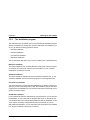
The functions of MT9750
LAN
The following connections can be implemented using LAN/CX:
– TCP/IP connections
– Mobile connections via mobile radio networks (MODACOM and D1/D2)
– ISDN connections
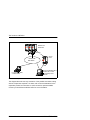
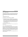
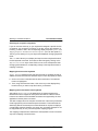
If you want to connect your PC to the BS2000 host via a TCP/IP LAN, the Windows TCP/IP network protocol must be installed and configured. In addition,
you will need a communication board to connect your PC to the LAN as well as
a cable to connect your PC to the LAN.
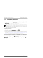
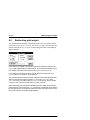
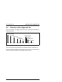
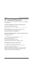
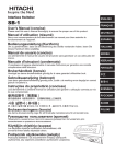
The following diagram provides you with a typical overview of the type of connection options in the TCP/IP LAN:
BS2000 host
with BCAM
9632/
HNC 91849
TCP/IP Local Area Network (LAN)
PC running Windows NT
PC running Windows 95
LAN connection options
Contact your local Siemens Nixdorf regional office if you require further information on this software as well as the cables and interface boards required.
Product Manual
U42006-J-Z795-1-7600
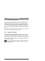
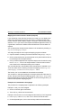
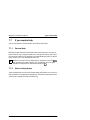
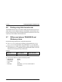
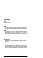
The functions of MT9750
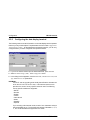
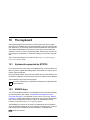
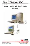
BS2000 host
with BCAM
SMCS-GW
Server/
router
MODACOM/
GSM MRTS
ISDN
PC with SMCS-MDC,
or SMCS-GSM
PC running Windows 95 or
Windows NT 4.0 and
appropriate protocol
software
WAN connection options
The diagram above shows only a selection of the possible connections along
with the components required. If in doubt, refer to the documentation for the
respective product for information on other connection options available.
Contact your local Siemens Nixdorf office for more information.
Product Manual
U42006-J-Z795-1-7600
The functions of MT9750
3.2
Original device
Original device functions supported
The functions supported by the 9750/63 data display terminal listed in the following section are emulated by the MT9750:
–
–
–
–
–
–
–
–
–
–
–
Unformatted and formatted mode
Color display and configuration
Programmable keys
Support for the 9750 function keys
Character generation
Support for 8-bit character sets
Configuration options for decimal characters, the cursor, and deleted display
space
Printing of host files to local printers (bypass printing)
Screen dump output to local printers (hardcopy)
Support for the following structured statements:
status message, status check, read P areas, define screen, reset screen,
and error messages
Support of extended attribute definitions
Product Manual
U42006-J-Z795-1-7600
The functions of MT9750
3.3
Original device
Additional functions
In addition to emulating the functions of a data display terminal, MT9750 offers
further functions:
– Executable under MS Windows 95 and Windows NT 4.0 as a true 32-bit
application
– It can be operated with menus and dialog boxes
– It offers user support by means of online help
– Characters can be resized automatically to suit the window size or can be
configured manually
– Sessions can be recorded for error diagnosis
– Multiple sessions
– Screen data can be copied and pasted to or from a file or to or from the Windows clipboard, and data can be transferred to a printer
– Screen data can be copied and pasted via the Windows clipboard
– Screen data can be copied via DDE (Dynamic Data Exchange)
– Automated data exchange with other applications via various programming
interfaces (DDE, EHLLAPI, Entire Connection, OLE automation)
– Communication via a LAN (Local Area Network)
– User-defined P keys and macro keys
– Windows to display the keyboard mappings with the option of starting
functions using the mouse
– Windows containing an individual selection of frequently required functions,
including user-specific P keys and macro keys
– PC and trimodal keyboards are supported
– A function for switching to an alternative character set in Cyrillic Windows
– An option for customizing the keyboard assignment to your individual
requirements
– Integrated macro recorder for automating functions
– File transfer for exchanging data between PC and BS2000 host:
either using the VFT product supplied or using openFT
– Conversion of existing session configurations from preceding versions
– Printing to PC printers that cannot be configured in the TRANSDATA network
– Printing the full screen contents regardless of the cursor position
Product Manual
U42006-J-Z795-1-7600
The functions of MT9750
3.4
Print functions
MT9750 print functions
MT9750 emulates the bypass and hardcopy print functions of the 9750. You can
also use the Windows Copy function which copies the contents selected in the
session window to the local printer. Further on in this section you will find more
information in this regard.
3.4.1
Bypass print
Bypass printing denotes the output of host data to a printer connected to a data
display terminal. The BS2000 Remote Spool Output (RSO) spool system is
generally used to do this. The data is output to the printer connected to the data
display terminal without being displayed on the screen. When bypass printing
with the emulation, you have the option of buffering the print data in one or more
files.
3.4.2
Hardcopy print
Hardcopy refers to the printout of the current session window. The hardcopy
size (number of rows and columns) is not based on the size of the current session screen visible, but the actual number of rows and columns in the session
as well as the position of the cursor.
You have the option of printing the output to a local printer connected to a PC
or to a file.
Hardcopies can be initiated in one of two ways:
– Manually, by pressing a hardcopy key or the mouse
– Program-controlled, by entering a corresponding key sequence
The programmed hardcopy is initiated by the BS2000 host. The message transferred is displayed on the data display terminal and once transfer is complete,
the print job is started or it is rerouted to a file. Keyboard input is not possible
until print output is complete.
With manual printing, the print job is initiated by a
also remains locked until print output is complete.
Product Manual
LAx
key. Here the keyboard
U42006-J-Z795-1-7600
The functions of MT9750
3.4.2.1
Print functions
Full-page hardcopy
Hardcopy printouts output the screen contents from the current cursor position
onwards to the printer. MT9750 offers you the option of printing the full screen
contents or of outputting it to a file, regardless of the cursor position. This form
of hardcopy is not initiated using a LAx key, but by selecting the Print Screen
menu item in the Session menu or by clicking on the toolbar button.
3.4.2.2
Copying to the printer
The option of copying screen data to a printer is an extension of the 9750 data
display terminal print options.
Data within the session window is referred to as screen data. You can select either all or part of the screen and then copy it to the local printer using the Edit:
Select All or Edit: Mark menu items. Data that is visible and printable is copied,
while invisible or non-printing data is displayed in the form of blanks. You can
also copy to a file or the clipboard.
3.5
Macro recorder
In order to automate constantly recurring functions (such as starting host applications using certain options) quickly and easily, an option has been implemented for recording user input, for editing using a simple programming language
(queries, loops), and for playing back user input as required. This function is
available by selecting the macro recorder.
Product Manual
U42006-J-Z795-1-7600
The functions of MT9750
3.6
Programming interfaces
MT9750 programming interfaces
MT9750 supports various programming boards that allow host data to be accessed via separate application programs:
– Dynamic Data Exchange (DDE) interface
– Emulator High Level Language Application Programming Interface
(EHLLAPI)
– Entire Connection
– OLE Automation
You can also integrate printer filters that allow the print data stream to be edited
or changed in line with your requirements.
For more information, particularly in relation to the functions supported and their
syntax, please refer to the MT9750 Programmer Reference Guide, the full
details of which can be found in the “Related publications” chapter.
Product Manual
U42006-J-Z795-1-7600
Preparing/configuring the product
4
Hardware and software
requirements
This section describes the hardware and software components required to operate the MT9750 emulation program .
4.1
PC
The requirements for using MT9750 depend primarily on the operating system
used. The minimum requirements for use are an 80486SX/DX or Pentium® processor and 8 Mbytes of main memory, these values increase considerably for
use under Windows NT. In addition, the memory requirements of other Windows applications which will be used must be taken into consideration. It is therefore essential when planning hardware that you take account of the operating
system specifications in particular.
The amount of free memory required on your hard disk depends on the components to be installed, but approximately 4 Mbytes should generally be sufficient. A CD-ROM drive is required if you are installing the full product or the
admin program (no client installation). The online documentation supplied is
also on CD-ROM and is read from there as required.
A VGA® monitor is required for MT9750. We recommend a resolution of at least
800x600 pixels and that it be configured with 32k colors.
MT9750 supports country-specific standard PC keyboards, as well as trimodal
keyboards.
You need Microsoft Windows 95 or MS Windows NT to run MT9750 V5.0. It
cannot be installed under 16-bit operating systems.
In addition, a suitable communication board (also called an interface board in
the following chapters) must be installed and configured in your PC for data
communication in the LAN. If you have questions on this subject, contact the
manufacturer or vendor of the communication board.
Product Manual
U42006-J-Z795-1-7600
Hardware and software requirements
4.1.1
Host software requirements
Connecting peripherals
You can use the printer configured under Windows from MT9750 to create your
hardcopies or bypass printouts. You can also connect various trimodal keyboards that have special BS2000 function keys and therefore simplify working
with the product.
4.2
Host software requirements
Ensure that the following software is installed on the BS2000 host:
BS2000 V9.5 or later and TCP/IP (BS2000) V2.1A or later. BCAM V.11 or later
must be running on the BS2000 host for bypass printing via a LAN.
i
If you want to use 8-bit character sets, an additional program (EHCS or
XHCS) must be installed on the BS2000 computer.
Product Manual
U42006-J-Z795-1-7600
5
Installation
This chapter describes the installation of the MT9750 software. It is divided into
the following sections:
The individual installation steps
This section explains the correct sequence for the installation process.
Installing the PC software
This section explains how to install the software on your PC.
Reinstalling components
The section explains the procedure for installing components at a later date.
Updating PC software
This section explains how to update a version of MT9750 (V5.0 or later) to a
later version.
Deinstalling MT9750
This section explains how to remove MT9750 from your system.
Product Manual
U42006-J-Z795-1-7600
Installation
5.1
The individual installation steps
The individual installation steps
When installing the MT9750 emulation, various components (BS2000 host,
data transfer facilities, interface boards, emulation software) are connected logically. You should note the sequence for installing the emulation described in the
following section to ensure smooth operation of MT9750.
– First establish whether your PC can connect to the BS2000 system via a
LAN connection. The host system administrator will be able to give you the
relevant information. You can also ask him what preparations he should
carry out for you on the host (this depends on the applications you want to
use).
– Ensure that you have a TCP/IP connection to the host (e.g. using the ping
<host-ip> command).
– Once you have set up the hardware required for operating MT9750, you can
start installing and configuring the software on your PC.
5.1.1
Selecting the language for the installation and user
dialogs
Once the setup program is started, a dialog box is displayed in which you can
select whether the setup program should be started in German or English. This
selection only defines the language of the distribution program and the language which is displayed for the manuals. The language for the installation of
MT9750 is selected at the beginning of the installation program (after calling up
“Installation“).The language you specify also affects the user interface of the
installed program, from the start-up menu entries to the emulation interface.
Product Manual
U42006-J-Z795-1-7600
Installation
5.2
Installing the PC software
Installing the PC software
MT9750 V5.0 is shipped with a user-friendly installation program that can perform a number of tasks for you:
●
Prepare a server for the network installation
●
Individual installation with various installation options
●
Reinstall components
●
Update a predecessor version (the predecessor version must be V5.0 or
later)
●
Deinstall the software
5.2.1
The administration program for preparing the
server
The administration program helps the server administrator to prepare for distribution of the program on the target systems. You can prepare a server for the
distributed installation and also generate diskettes (or images) for the local
installation of the program.
With server preparation, all of the MT9750 files, including an executable SETUP
program, are stored on the server in a resource. The SETUP program is called
later from the client and performs the installation as required by the user at the
PC. During the installation process, the user can specify that only the configuration files are to be copied to the client and the program files are to be called
on the server (the so-called distributed installation). The administrator can, in
turn, store pre-prepared configuration files on the server.
Product Manual
U42006-J-Z795-1-7600
Installation
5.2.2
Installing the PC software
The installation program
The options that you are offered when you call the MT9750 installation program
depend on whether you already have a version of MT9750 V5.0 installed. If you
do not, you have the following selection options:
– Minimum installation
– Standard installation
– User-defined installation
– Distributed installation
You are offered the last option only if you are installing from a prepared server.
Minimum installation
This option installs only the necessary MT9750 components. Further programs,
for example VFT (Virtual File Transfer) are not installed. You can, however,
install these at a later point in time.
Standard installation
This option installs the standard elements contained in MT9750 V5.0, i.e. the
emulation, KBDMAP, and the conversion program for old configuration files.
User-defined installation
You should only perform a user-defined installation if you already know the program (e.g. from the preceding version). With this installation type you select the
components to be installed from a list. All of the files that are required for a component are always copied.
Distributed installation
If you install the MT9750 V5.0 software from a prepared server, you can perform
the installation in such a way that the program files remain on the server and
your Windows start menu contains appropriate links after the installation. In this
case, only the necessary configuration files are copied locally to your PC.
With distributed installation, you can also select the components to be installed
from the list of available components, if required.
Product Manual
U42006-J-Z795-1-7600
Installation
5.2.3
Installing the PC software
Reinstalling components
You can also use the installation program to add further components to an existing MT9750 installation. To do this, call the SETUP.EXE program from the
installation medium once again. The program recognizes the existing installation and offers you options for reinstalling or updating MT9750. Click on Add
Component to extend the installation and go to the component selection option.
Then select the relevant component(s) and proceed as for the first-time installation.
Your software is automatically updated during a reinstallation which guarantees
that the software modules installed remain consistent.
5.2.4
Updating PC software
MT9750 allows the automatic updating of program files. To do this, call the
SETUP program from the installation medium and click on Update. The program
components that are already installed are recognised and, if necessary, replaced by the current versions. This does not overwrite existing configuration files.
A current version is not updated, instead you are informed that you already have
the current version installed.
i
When you reinstall or update your software, the language selected in the
first-time installation is retained regardless of the language selected in
the installation dialog.
Product Manual
U42006-J-Z795-1-7600
Installation
5.3
Guidelines on the individual connection types
Guidelines on the individual connection
types
The following section contains guidelines that should be observed with regard
to the individual connection types or references to related documentation.
5.3.1
Connecting via TCP/IP LANs
MT9750 supports the TCP/IP protocol stacks of the following products:
– LAN1 Pro V5.0
– Windows 95
– Windows NT 4.0
You can connect your PC to a local network with one of these products. Information on how to install these products on your PC can be found in the LAN1
software from Siemens Nixdorf or in the Windows documentation from Microsoft.
Mapping names to IP addresses
To address the host using symbolic names, the TCP/IP host names must either
be mapped to host IP addresses in the file lmhosts (e.g. <Windows directory>:\System32\drivers\etc\lmhosts) or (generally) on a name server. This
depends on the configuration of your network. You can however also access the
host directly via the corresponding IP addresses. In this case you do not need
an lmhosts file.
Connecting via a WAN using ISDN-Connect
In addition to the integration of PCs in a LAN, there is an increasing need to connect individual PCs beyond the scope of the local network. Typical examples of
this are the networking of individual PCs in branch offices or laptops for field
workers. ISDN-Connect (included in LAN1 from Version 3.0B on) allows
MT9750 to communicate with BS2000 via wide area networks (WAN). The following transmission variations are offered:
– TCP/IP via ISDN
– TCP/IP via DATEX-P (X.25)
– TCP/IP via GSM (D-Network)
Product Manual
U42006-J-Z795-1-7600
Installation
Installing printers
You can find further information on software and hardware requirements in the
relevant product documentation.
5.3.2
Connecting via the MODACOM mobile radio data
network
Connections to the German Telekom® MODACOM mobile radio data network
can be implemented via TCP/IP. To do this, you need the SMCS-MDC product
from Siemens AG and a suitable modem.
From the point of view of the emulation, this type of configuration is completely
transparent, i.e. the necessary steps for configuration are carried out in the
underlying products.
5.3.3
Connecting via the GSM mobile telephone network
Connections to the GSM mobile telephone network (D1/D2 or E-plus) can be
implemented via TCP/IP. To do this, you need the SMCS-GSM product from
Siemens AG and a suitable modem.
From the point of view of the emulation, this type of configuration is completely
transparent, i.e. the necessary steps for configuration are carried out in the
underlying products.
5.4
Installing printers
The procedure for installing printers connected directly to the host is not described in this manual. To find information on this, read the relevant printer or host
manual.
Product Manual
U42006-J-Z795-1-7600
Installation
Deinstalling MT9750
Local printer
You can use a Windows printer connected to your PC from MT9750 for printing
host files.
A Windows printer can only be connected to a port supported by Windows
(LPT1, LPT2, LPT3, COM1, COM2, COM3, COM4). Further information on this
can be found in the Microsoft Windows User Guide.
Information on configuring local printers under MT9750 can be found in the section “Configuring the printer” in the “Configuration” chapter.
5.5
Deinstalling MT9750
Proceed as follows to delete the MT9750 software from your system and undo
the entries in the Windows registry:
Ê Double-click on the Software icon in the Control Panel. You can access the
Control Panel window under Start: Settings: Control Panel.
Ê The Add/Remove Programs dialog box lists the software installed on your
system. Depending on the installed components, it also contains the
MT9750 entries: Siemens Nixdorf MT9750 V5.0, Siemens Nixdorf KBDMAP, Siemens Nixdorf VFT32.
Ê Select the components that you want to remove from your system and confirm your selection by pressing the Add/Remove ... button. A dialog box for selecting the delete dialog language is displayed.
Ê Confirm your preferred language with OK. A dialog box containing information on the software components selected for deletion is displayed. You can
still cancel deletion of the software by pressing the Cancel button.
Ê If you are sure that you want to delete the displayed components, confirm
the dialog box with OK and the software and the registry entries are removed
from your system.
Ê Repeat this procedure for each component to be deleted.
Product Manual
U42006-J-Z795-1-7600
6
Configuration
Once you have installed MT9750 you can configure the emulation for use. This
chapter describes how to configure and customize sessions in MT9750.
6.1
Preparatory steps
If MT9750 was already configured for you, continue with the chapter “Working
in emulation sessions“ which describes the operation of the configured emulation program.
The following preparatory steps must be carried out before calling MT9750 for
the first time:
Ê Ensure that the TRANSDATA network is already configured for MT9750. If
in doubt, consult your system administrator.
Ê Make sure that the TCP/IP software that you want to use is installed and correctly configured.
Ê Install MT9750 (see the chapter “Installation“).
You can now start MT9750 via the entry in the start menu under Programs:
MT9750 32 bit: MT9750. However you must configure a session before you can
connect to a BS2000 host.
6.2
MT9750 session
A session is a window in the emulation where the host data is displayed. It may
have a title and is saved under a filename. Each session is allocated parameters that determine its attributes, the assignment of programmable keys, and the
connection. The parameters are set for each session individually and are only
valid for the respective session.
When configuring your sessions, you can set the various parameters to your
own requirements. If you communicate with various BS2000 hosts regularly,
you can configure separate sessions for each of them. You then only have to
re-open the session to establish the connection with a certain host.
Product Manual
U42006-J-Z795-1-7600
Configuration
MT9750 session
You can also work with different character formats in the various host application (i.e. small format characters are better suited to spreadsheets than large
format ones) or with different P key assignments.
You have to configure a session if you are calling MT9750 for the first time.
6.2.1
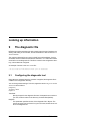
Configuring a session
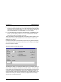
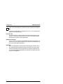
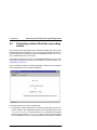
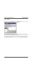
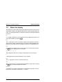
Ê Select New in the Session menu. The following dialog box is displayed:
Ê Enter a title (optional) of not more than 40 characters for your session in the
Session text box.
Sessions are configured in RFC1006 format by default. If you require LAN-INET
connections that deviate from this, you can activate the check field. The manner
in which you proceed differs from the RFC1006 default setting. In this case,
read “Using the LAN-INET format“.
Product Manual
U42006-J-Z795-1-7600
Configuration
MT9750 session
Ê In the Partner field, enter the Host Name as well as the host Application (optional) that you want to work with. As you can see, the default port for RFC1006
connections (102) is entered under Port Number. This cannot be changed. If
you require another port, you must change to LAN-INET format.
Ê If your host application is expecting a specific station for establishing a connection, you can specify it under Local: Station; otherwise leave this field
blank and the station is allocated dynamically.
These specifications are generally all that are required to define a session. You
can therefore confirm your specifications with OK and the connection to the
BS2000 host is opened.
Further advanced options are required for specific uses (e.g. passive sessions).
You can specify these options if you click on the Advanced button in the dialog
box for configuring a session.
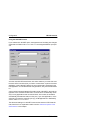
Advanced options of the 9750 session
This dialog box allows you to specify the station type of your session, specify a
short name, and modify the mode (active or passive session). The station type
is needed by some host applications to check the characteristics of the terminal
connected. However the parameters affect only the establishment of the connection and have no effect on the characteristics of your emulation session. The
session short name (one character) is used by PC applications to exchange
data with the corresponding session.
Product Manual
U42006-J-Z795-1-7600
Configuration
MT9750 session
You can also specify other options for starting the emulation session:
– Reconnect on Startup means that the session is opened automatically when
the emulation is started.
– Specify Start iconized if the session is to be started as an icon (e.g. for bypass
printing in the case of passive sessions).
– Save in Group means that the session appears as a separate entry in the start
menu in which you can start the session (and the emulation).
– The Net Password Requested option means that a dialog box for entering the
password is displayed in networks where access is safeguarded using a network password. Alternatively you can specify the network password as well
as a user message in the Connection field under Advanced Options at the session configuration stage. In this case the session uses the specified password.
i
Note that you can only enter the password when you first configure a session. You cannot display or change it later.
Once you have entered all information relating to the emulation session, confirm
it with OK.
With an active session, the session window with the BS2000 login prompt or the
BS2000 application is now displayed on the screen. A passive session (see
page 40) is started as an icon and waits for a connection to be established by
the host.
Product Manual
U42006-J-Z795-1-7600
Configuration
MT9750 session
Using the LAN-INET format
If you activate the LAN-INET option, the appearance of the dialog box changes
somewhat: the fields under Partner and Local are assigned different input options.
As is the case with RFC1006 format, with active sessions you must also enter
the name of the host with which you want to communicate. In place of the host
application, under LAN-INET specify the port number that is generated in the
host application. If in doubt about the host generation, ask your host administrator.
A port number is entered instead of the station under LAN-INET in the local configuration of the emulation session also. However this is not absolutely necessary in many applications and can remain blank. In this case, the emulation
automatically allocates the session a free port. If your host application, on the
other hand, is expecting a specific port (e.g. UTM applications or filetransfer),
enter it under Local: Port Number.
The advanced settings in LAN-INET format are the same as in RFC1006 format; therefore for an explanation read the section “Advanced options of the
9750 session“ in this chapter.
Product Manual
U42006-J-Z795-1-7600
Configuration
6.2.1.1
MT9750 session
Passive sessions
Passive sessions play a special role. In most cases they are needed to implemented bypass print connections. In contrast to active sessions, when configuring a passive session you specify the local station (or the local port number
under LAN-INET) that is reserved for the passive session instead of a host
name.
Configuring a passive session
Ê Select the Advanced button in the Session: New dialog box.
Ê Click on the Mode: passive option and confirm with OK.
Ê This returns you to the Session: New dialog box. Various specifications are
required under Local depending on whether you require LAN-INET format:
If you are working in the default format (RFC1006), specify the name of the
local Station; otherwise (LAN-INET option active) the number of the local port
that is intended for your passive session. In LAN-INET format, the Port Number to be used is generated in the host application that initiates establishment of the connection.
Ê Confirm the specifications with OK.
The passive session is started immediately as an icon; you do not have to configure this yourself.
6.2.1.2
Saving a newly configured session
Once you have configured a session it is started. The relevant host application
is started if the connection parameters are specified correctly. You must save
this session if you want it to be available the next time you use MT9750. To do
this, select Save As ... in the Session: menu and specify a name. The name must
adhere to the naming conventions for Windows 95 or Windows NT, i.e. it can be
longer than 8 characters in length. It must, however, have the filename extension .MTS. Once you have configured and saved a session in the manner described above, you can reopen it at any time.
Read the following section for information on how to adapt the session to your
individual requirements.
Product Manual
U42006-J-Z795-1-7600
Configuration
6.2.2
MT9750 session
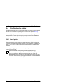
Configuring the data display terminal
The following sections contain information on the data display terminal parameters that you may need to adjust. The parameters are found under Configuration:
Terminal Settings (DSS).... As the parameters are session-specific, you can only
configure them if you have configured and opened a session.
Ê If you do not have a session open as described above, open one now.
Ê Select Terminal Settings (DSS)... in the Configuration menu.
Ê In the dialog box that appears, enter the DSS Mode, DSS Interconnection, DSS
Type, and Character Set parameters.
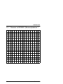
DSS Mode:
DSS mode sets an operating mode locally that affects the character set
to be used. If 7-bit DSS mode is set, a 7-bit character set that corresponds to the current country-specific variant is used. The following
country-specific variants are supported:
– Danish
– German
– English
– French
– International
– Italian
– Swedish
– Spanish
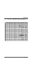
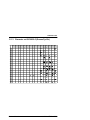
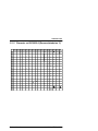
If you are using 8-bit character mode, a total of 191 characters and symbols are available to you. The character set variants of the 8859-1, -2, -5,
-7, and -9 ISO standard are supported in this mode.
Product Manual
U42006-J-Z795-1-7600
Configuration
i
MT9750 session
DSS mode should always be matched with the respective host application.
If you want to work with 8-bit character sets, EHCS or XHCS must also be
installed on the BS2000 host.
Character Set:
This specifies which national character set should be displayed on the
screen in 7-bit mode (or 8-bit mode if you wish). Choose the character
set here that is used by the host application.
DSS Interconnection:
If your computer is specified in the BS2000 generation as attached to a
computer, you can expect mistakes in the character representation and
you must change these parameters.
DSS Type:
Some host applications check the type of data display terminal connected. MT9750 sessions respond as 9750 data display terminals unless
otherwise specified. If the host application is expecting a different type,
you can change the MT9750 parameter so that the host application does
not have to be adjusted.
Product Manual
U42006-J-Z795-1-7600
Configuration
6.2.2.1
MT9750 session
Special terminal parameters
Certain events that occur while working with MT9750 are displayed and queried
using messages. The related operator actions may disrupt the work in the emulation in certain circumstances. You have the option of disabling the following
dialogs in the Configuration: Special Parameters ... dialog box:
– Dialog for modified session parameters
– Connection shutdown dialog (TCP/IP connections)
Click on the desired option to disable the corresponding message. In the case
of modified session parameters, the changes are stored automatically.
The Partner Characteristics parameter only relates to passive sessions and is
described in the next section.
6.2.3
Configuring passive sessions
Passive sessions are required in LAN connections to allow bypass printing. To
do this, a session with a passive connection name is opened. This initializes itself as an icon and waits for a connection request from the host. Passive sessions can also be provided for dialog applications in which the connection is established by the host.
If the host application uses information about the attributes of the data display
terminal (partner characteristics) to edit the (print) data stream, you also have
to change the Partner Characteristics parameter to configure the printer (see
below). These parameters can be found under Configuration: Special Parameters:
Terminal/Printer. Click on the setting long. Generally, however, this parameter
need not be changed.
Product Manual
U42006-J-Z795-1-7600
Configuration
6.3
Converting session files from a preceding version
Converting session files from a preceding
version
If you already have a preceding version of MT9750 installed and want to retain
the existing session configuration, you can use a program supplied for this very
purpose that converts the data from the old configuration files (CONNECT.INI,
DIR1, and MTS files) to the new format.
You call the conversion tool (MTKonv) from the MT9750 start group. You must
reinstall the component if this entry is not available. For more information, see
“Reinstalling components“.
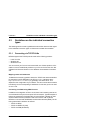
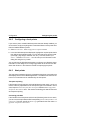
Once you call the program, the following interface in which you enter the paths
of the configuration to be converted is displayed.
Proceed as follows to convert the session files:
Ê First specify the files in which the old connection configuration is stored. To
do this, change to the configuration directory of the preceding version under
Conversion: Select connect.ini and select the connect.ini file used. Then specify
the DIR1 file used under Conversion: Select DIR1. For both menu items used,
the icons labeled “C” and “D” are also available when the toolbar is enabled.
Product Manual
U42006-J-Z795-1-7600
Configuration
Converting session files from a preceding version
Ê Open the MTS file to be converted using the File: Open menu.
Ê Now start the conversion by selecting Conversion: Generate single. The session file to be converted is now transferred to the new format.
Ê Save the new session file in the MT9750 V5.0 configuration path. To do this,
use the File: Save As ... menu.
If you want to continue to use a number of session files from your configuration,
you can start the configuration process using Conversion: Automatic instead of
Conversion: Generate single. In this case, all session files in the selected path are
converted one after the other.
For single or automatic conversion, you can also use the symbols in the toolbar
labeled “E” and “A” respectively.
Once you have converted and saved all the sessions, you can terminate the
program and deinstall it if necessary. You can then access the converted configuration files under the new installation in the form of session files that you
simply need to open.
Product Manual
U42006-J-Z795-1-7600
Configuration
6.4
Configuring the printer
Configuring the printer
This section describes how to configure MT9750 to print screen contents as well
as host files. Information on printing can be found in the chapter “Printing“.
When configuring a printer, a distinction is made between adjusting to the print
data stream that comes from the host (host printer) and the print data stream
that goes to the connected printer (local printer).
6.4.1
Local printer
The local printer is a printer that is connected to your PC. MT9750 allows the
connection of printers supported by Windows. The local printer configuration is
global, i.e. it is not only valid for the current MT9750 session, but all MT9750
sessions.
Hardcopy printing (complete or screen shots) and bypass printing are performed on the local printer.
i
Points to remember when printing host files (bypass printing):
If you are using a Windows printer that is different from the one specified
in the host generation, MT9750 converts the host data. To do this,
MT9750 must know the format of the print data sent from the host. The
conversion is configured by specifying the host printer. For more detailed
information see the section “Host printer“.
Product Manual
U42006-J-Z795-1-7600
Configuration
6.4.2
Configuring the printer
Configuring a local printer
If you want to print to a default Windows printer that was already installed, you
do not need to configure anything else. Proceed as follows to use a printer other
than the installed Windows printer:
Ê Select Local Printer... in the Configuration: Peripherals menu.
Ê In the list of Windows printers displayed, highlight the required printer that is
then defined as the default printer. You can also change the printer format
(line length, page length, character size, etc.). To do this, select Define
Printer ... and then Print Format ... You can call up more information in this
dialog box using the Help button.
You can also use the Windows mechanism to configure your Windows printer.
Information on the dialog box for configuring printers can be found in the Windows User Guide or in the reference manual accompanying the printer.
6.4.3
Host printer
The host printer is whatever printer is generated as the printer connected to the
data display terminal in the BS2000 generation. The data that is sent from the
host is in a format that can be understood by the host printer.
Transparent printing
If the formats of the host printer and local (Windows) printer match, you do not
need to make any adjustments to the host printer type in the emulation. In this
case, keep the Printer Data from Host: Transparent default in the Configuration:
Peripherals: Host Printer menu. This method of handling print data is referred to
as transparent printing.
Converting print data
If the formats of the host printer and the local (Windows) printer do not match,
you can convert the print data to GDI format (setting: Printer Data from Host: Non
transparent). To do this, specify the Printer Type generated in the host under Configuration: Peripherals: Host Printer.
Product Manual
U42006-J-Z795-1-7600
Configuration
Configuring the printer
After its conversion, the print data is forwarded and output to the configured
Windows printer.
The following formats are supported:
–
–
–
–
–
–
–
9001 format
9011 format
9012 format
9013 format
9022-200 HP LaserJet format
9022-200 Diablo 630 format, and
IBM Proprinter format
Other formats can be emulated using the Printer Definition Language (PDL).
For information on how to do this, please refer to “The Printer Definition Language”.
Printer type in a passive session
For bypass printing, a separate session is required that is defined as passive
and waits for a connection to be established by the host. When establishing a
connection, the printer properties are checked by some host applications. In
order to operate existing host applications as they are, an option was provided
in MT9750 to configure the session in such a way that the expected session properties (in particular the printer type) are reported when the connection is being
established. To do this, go to the Configuration: Peripherals: Host Printer menu.
Product Manual
U42006-J-Z795-1-7600
Configuration
Configuring the printer
Ê Enter the printer generated in the host under Printer Type and the row length
that you would like for your printout under Maximum Row Length. This value
can be used by the host application to print data.
i
Unlike transparent printing (Printer Data from Host: Transparent option
active), with the Printer Data from Host: Non transparent option, you can
only specify printer types for which conversion into GDI format is supported (see the section “Converting print data“).
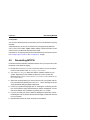
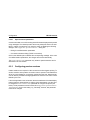
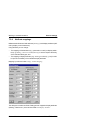
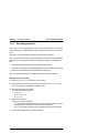
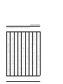
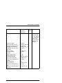
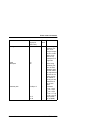
The following table explains the effects of setting the print type in the various
print modes relating to active/passive sessions as well as print output to WIndows printers:
Print data conversion
No print data conversion
Active session
Conversion to corresponding GDI No effect
format
Passive session
Conversion to corresponding GDI Identification to the host
format as well as identification to
the host
For passive sessions, the following special features of transparent printing also
apply.
6.4.3.1
Special features of transparent printing
The default for bypass printing with MT9750 is transparent printing (Printer Data
from Host: Transparent option).
This mode should – insofar as possible – be used as the print jobs are processed considerably quicker. In addition, this mode offers you the option of accessing the data stream using two mechanisms:
– Replacement characters for ESC
Certain host applications do not use the default control character ESC
(Escape) for the printer controller. In order to be able to continue to use
these applications without needing adjustment, you have the option of specifying this character that the emulation converts to ESC before the data
stream is forwarded to the printer. You define the replacement character in
Product Manual
U42006-J-Z795-1-7600
Configuration
Configuring the printer
the Configuration: Special Parameters menu. Specify the character in its
hexadecimal form (e.g. 1b for ESC).
– Printer filter
If you want to connect a Windows printer whose function range deviates
from that of the host printer, you have the option of linking in separate printer
filters that you can customize yourself. To activate this type of filter, enter the
file in the Configuration: Printer Filter: Enter... menu that contains the filter
functions. A source code example for a filter is supplied with the FILTER.C
file. You can customize this filter to your individual requirements (more information on this can be found in the Programmer’s Reference Guide).
Product Manual
U42006-J-Z795-1-7600
Configuration
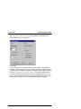
6.5
Troubleshooting
Troubleshooting
An emulation program is a software product that cannot operate unless the following components are configured correctly:
●
PC
●
Interface boards
●
Host
In addition, you should check the following points if you have problems:
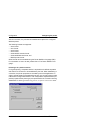
6.5.1
Configuring MT9750
Ensure that the correct character set is selected in the DSS Mode dialog box in
the Configuration menu.
If necessary, check the setting of the DSS Type as well.
6.5.2
Connection
You may have made a mistake when setting the connection method.
Ensure that the host name you entered matches either the host name configured on the name server or the host name in the lmhosts file.
6.5.3
BS2000 host
Communication errors may be caused by the host generation. To see if this is
the case, check the following:
Communicating with the BS2000 host
The following command line - which you enter at an MS-DOS prompt - can be
used to check whether the host is responding to your input at all:
ping [host_name] or ping <IP_address>
Product Manual
U42006-J-Z795-1-7600
Using the emulation
7
Working in emulation sessions
This chapter describes the functions you can use to work with MT9750. The following topics are dealt with in separate sections:
–
–
–
–
–
–
Administering the sessions
Session settings
Exchanging screen data
Emulation utilities
Character generation
Messages in the BS2000 status line
Guidelines on use
Windows programs are generally used with a mouse. MT9750 also offers many
operational advantages if a mouse is connected to your PC. In the following
description, it is assumed that for the most part you are using MT9750 with a
mouse.
You can also use MT9750 without a mouse; in this case use the menu key combinations. If in doubt, consult the Windows User’s Guide.
Mouse pointer and cursor
The mouse pointer has the shape of an arrow, while the BS2000 cursor within
the session window is represented by a block or underscore character (depending on the configuration). In this manual, “cursor” refers to the mouse pointer
and “BS2000 cursor” the cursor within the BS2000 session window.
There is also a position indicator that is used in the context of “Copying screen
data”. This is represented by a vertical block and is called a marking cursor.
Product Manual
U42006-J-Z795-1-7600
Working in emulation sessions
7.1
Administering the sessions
Administering the sessions
The chapter “Configuration” contains a description of how to configure a session. A prerequisite for the following sections is that you have already configured one or more connection names and a session
You can open and edit existing sessions, save changes, or configure new sessions.
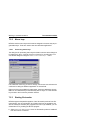
7.1.1
Opening sessions
There are a number of options for opening sessions:
– Opening automatically when the emulation starts
With this option, the sessions to be opened were saved using the Reconnect
on Startup option (see also “Editing sessions”).
– Opening one of the last four sessions
After selecting Session, the last four sessions that were opened are displayed. You open these by clicking on them.
– Opening a saved session
After selecting Session: Open search for the required session using the directories displayed and open it.
– Opening a temporary session
After selecting Session: Temporary Session, a dialog box is displayed in which
you can specify the connection parameters in the same way as when configuring a new session. If you have questions on this, see “Configuring a session“.
– Opening a new session
The section “Configuring a session“ explains in detail how to open a session.
Refer to this section now if necessary.
– Opening a session using its icon
If you specified when saving a session that this session is to be started as
an icon, you can open the corresponding session by double-clicking on the
icon in the Emulations group.
Product Manual
U42006-J-Z795-1-7600
Working in emulation sessions
7.1.2
Administering the sessions
Editing sessions
You can use the Session: Edit menu to edit sessions. The following dialog box is
displayed:
Here you can see and change the connection parameters of the selected session. The advanced parameters (with the exception of the network password)
are also available. If you need information on the individual parameters, refer to
the section “Configuring a session“ in the “Configuration” chapter.
7.1.3
i
Saving a session
Saving a session does not refer to saving the session data displayed in
the window. Instead, the session parameters such as the character format, session title, display mode, P key assignment etc. are saved.
If you do not specify a directory in which your session is to be saved, the
MT9750 sessions are saved in the configuration directory.
The various options for saving sessions are described in the following sessions.
Product Manual
U42006-J-Z795-1-7600
Working in emulation sessions
Administering the sessions
Saving an active session:
Ê Choose Save from the Session menu.
The session window remains active after the save. You are only prompted to
enter a filename if you are saving a new session. If the session was saved
already, the original filename is used.
Saving a new session or an existing session under a new filename
Ê Select Save As in the Session menu.
Ê Enter a filename for your session in the Save Session As box. You can also
change the directory if you wish. The filename must have the extension .MTS
(e. g. PULS.MTS).
Ê If you want to save the programmable keys assignment with the new session, click on the Save Programmable Keys option. The assignment is then
saved in a file with the filename extension .MTS.
Ê Confirm the information with OK.
The session window remains active after the save.
The Save As option always prompts you to enter a file name, regardless of whether or not the file was saved previously. Using this option, you can save new
sessions or save an existing session under a new name.
Saving all open session windows
Ê Select Save All in the Session menu.
Using this option you can save changes to all the session that are open. The
session windows remain open after the save.
Product Manual
U42006-J-Z795-1-7600
Working in emulation sessions
7.1.4
Administering the sessions
Closing a session
If you want to close individual sessions, you can either use the Session: Close
menu item or the session control menu. If you exit the emulation program, all
sessions still active are closed automatically.
If you have made changes to your session parameters since the last time you
performed a save, you are asked in a dialog box whether you want to save the
changes, provided you have not activated the disable messages option in the
Configuration: Special Parameters ... dialog box.
7.1.5
Working with multiple sessions
The emulation program offers you the option of running applications in various
session windows in parallel. To do this, simply open other sessions in the Session menu. You can use the Window menu item to determine how the various
session windows are to be displayed: cascaded or tiled. When working with a
number of windows (sessions) you can also use this menu to determine which
window should be active.
Terminating multiple sessions
All open sessions are closed when you terminate the emulation program. The
sessions do not have to be closed individually. The Close All option under the
Window menu item is also available to you for quitting sessions.
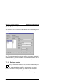
7.1.6
Deleting a session
Select Session: Delete to delete a session. In the dialog box that is displayed, you
can use a directory list to change to the directory in which the session to be deleted is saved. The configuration directory is displayed as the default. Once you
have selected the session to be deleted, the session attributes are displayed so
that you can check them. If you are sure that you have selected the correct session, confirm the selection and the subsequent request for confirmation with OK
and the session is deleted.
Product Manual
U42006-J-Z795-1-7600
Working in emulation sessions
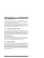
7.2
Session settings
Session settings
Each session has settings relating to the display attributes and the keyboard
mappings. The display attribute settings are divided into terminal setup and
color mappings, font, and attribute mappings.
7.2.1
Terminal setup
You can access the terminal setup options via the Settings: Terminal menu.
You have the option of configuring decimal characters, the cursor, and the
NULL character in the Setup Terminal dialog box. In addition to configuring the
appearance of the cursor, you can also specify how the cursor can be positioned using the mouse (single click or double click), and the position of the cursor
after insert operations (this is important, for example, for automating processes). You can also change the appearance of the screen: you have a choice
between displaying light characters on a dark background and vice versa as
well as the option of displaying the status line. Activate the Store Window Position
option if you want to retain the window size and position for later use or when
you close the session. Finally, you can use this dialog box to define the Enter
key on the numeric keypad as a second data transmission key.
Product Manual
U42006-J-Z795-1-7600
Working in emulation sessions
7.2.1.1
Session settings
Displaying the cursor position
When you are automating data communications, it is helpful to know the position of the cursor since this is used by the MT9750 programming language
functions. Activate the Show position option under Cursor Shape; additional information in the status line (e.g. 2/40) indicates the position (line/column) of the
cursor.
Linear specification of the cursor position
The linear specification of the cursor position is the position specified as an integer, which is calculated as the following sum:
(columns per line x (cursor line-1)) + cursor column.
Example:
The position 5/24 (5th. line/24th. column) gives the following result for a screen
size of 24x80: 80 x (5-1) + 24 = 344
The linear position is displayed in the status line if the MTS file for the session
in question contains the following entry:
ShowCursorPosLin=1
Product Manual
U42006-J-Z795-1-7600
Working in emulation sessions
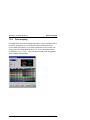
7.2.2
Session settings
Color mapping
Host applications use colors to highlight information. If you do not like the colors
chosen for this purpose, you can map these colors to alternative colors.
A color palette from which you can select a replacement color for each color
used by the host is displayed under the Colour Mapping dialog box which is
accessed via Settings: Colours... The color palette complies with the graphics
driver installed under Windows.
Product Manual
U42006-J-Z795-1-7600
Working in emulation sessions
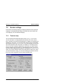
7.2.3
Session settings
Font
Use the Font Selection dialog box (this is accessed via the Settings: Fonts... menu)
to define the font to be used for the screen output.
You can choose between having a font selected automatically to fit the window
size of the session or selecting a specific font.
The selection of fonts ranges from 6 x 10 pixels to 12 x 28 pixels. Set fonts can
only be selected when the Automatic Font Selection check box is not activated.
Product Manual
U42006-J-Z795-1-7600
Working in emulation sessions
7.2.4
Session settings
Attribute mappings
BS2000 mask fields have field attributes (Field Type) and display attributes (defined by display control characters).
Using MT9750 you can change:
– The mapping of field attributes (e. g. protected or numeric) to display attributes (e. g. Blinking, Underscored or Half Intensity) in order to improve the clarity
of the individual field types, and
– The mapping of display attributes (e. g. Blinking) to colors (e. g. red) in order
to improve the visibility of the individual display attributes.
Mapping is performed under Settings: Attribute Mapping.
.
The dialog box contains two fields. Field types are mapped to display attributes
(blinking, underline etc.) in the left-hand field Field Display Attributes.
Product Manual
U42006-J-Z795-1-7600
Working in emulation sessions
Session settings
You can activate your own mappings with the Use Mappings check box. Otherwise the use of display attributes depends on the host application.
This option is only available if a session window is already open.
Mapping field types to attributes:
Ê Select Attribute Mapping in the Settings menu.
Ê Select a Field Type.
Ê Select the Attribute to which you want to map the field type.
Ê Repeat these steps for each field type that you want to map to a display attribute.
Ê Select the Use Mappings check box if you want to work with the mappings.
Ê Select OK.
The right-hand field Attribute Mappings is only relevant for color screens. If you
are working with a monochrome monitor, select the Monochrome Terminal check
box in the lower field to deactivate all settings displayed here – the session window then has the display attributes of a monochrome terminal.
Mapping attributes to colors:
If you are using a color screen, you can map a color to a display attribute.
Ê Select Attribute Mapping in the Settings menu.
Ê Select the Attribute to be changed from Attribute Mappings.
Ê Select the color to which you want to map the attribute.
Ê Repeat these steps for each attribute.
Ê Ensure that the Monochrome Terminal check box is not selected.
Ê Confirm the mapping with OK.
Product Manual
U42006-J-Z795-1-7600
Working in emulation sessions
7.3
Exchanging data
Exchanging data
The use of modern terminal emulations on PCs allows data to be exchanged
between host applications and PC applications and data to be reprocessed
using user-friendly Windows applications. MT9750 offers a number of options
for managing data exchange:
– Via the clipboard (copy and paste)
– Using the DDE mechanism (only with Windows applications that support
DDE)
– Via a separate DDE interface (with separate DDE applications – you can find
information on creating separate DDE application programs in the Programmer Reference Guide)
7.3.1
Copying and pasting screen data
Copying and pasting of data relates to data within the session window. Data
within the session window is referred to as screen data in the following description. Using the functions of the Edit menu item, you can select all or part of the
screen data and then copy and paste it.
7.3.1.1
Copying screen data
Screen data can be copied to one of the following targets in part or in full:
– To the clipboard
– To a file
– To a printer
Screen data can only be copied if you have already marked a screen area in the
active session window.
i
Invisible and non-printable text (e. g. a password) remains invisible after
copying to guarantee data security. Note that only the characters themselves, i.e. no attributes (e.g.underscore, bold), are copied and not all
BS2000 characters can be displayed.
You can choose between copying all or part of the screen data.
Product Manual
U42006-J-Z795-1-7600
Working in emulation sessions
Exchanging data
Copying part of the session
Ê Open a session.
Ê Using the mouse, select the right-hand corner within the session window
that you want to copy. If you are not working with a mouse, proceed as follows:
Ê Using shift + cursor control key, or the Mark menu item in the Edit menu,
switch to marking mode.
Ê Define the start of the area to be copied using the cursor control keys.
Ê Holding down the shift key, mark the area to be copied using the cursor
control keys.
Ê Select Copy in the Edit menu.
Ê Select the destination for the data that is to be copied in the cascading Copy
menu.
Copying the full active session window
Ê Open a session.
Ê Choose Select All in the Edit menu.
Ê Select Copy in the Edit menu.
Ê Select the destination for the data that is to be copied in the cascading Copy
menu.
i
Using Select All, all the data displayed in the current active MT9750 window (without the BS2000 status line) is selected. This includes the
screen data that is not currently in the area displayed.
i
Note when copying to a file:
The name of the target file should be a valid DOS file name with the filename extension .DMP.
Product Manual
U42006-J-Z795-1-7600
Working in emulation sessions
7.3.1.2
Exchanging data
Pasting screen data
Data can be pasted from one of the following sources:
– From the clipboard
– From a file.
Proceed as follows:
Ê Open a session.
Ê Position the cursor at the location in the screen where you want to insert the
data.
Ê Select Paste in the Edit menu.
Ê Select the source of the data to be pasted in the cascading Paste menu.
i
Data cannot be pasted to protected fields. In this case, the message ERR
is displayed in the 9750 status line.
Product Manual
U42006-J-Z795-1-7600
Working in emulation sessions
7.4
DDE data exchange via the clipboard
DDE data exchange via the clipboard
DDE (Dynamic Data Exchange) is a mechanism for establishing and administering links between various Windows applications. The linked applications can
then exchange and update their data automatically.
MT9750 supports DDE data exchange in two ways: DDE data exchange via the
clipboard and DDE communication using DDE data elements. Since DDE data
exchange via the clipboard is considerably easier to set up and given that more
recent Windows applications no longer support DDE communication via data
elements, we recommend that you use the clipboard to exchange data. The
(outdated) method is only supported for reasons of compatibility. (The description of data exchange via DDE data elements can be found in the Appendix
under “DDE data exchange“).
The following steps are required for exchanging data using DDE via the clipboard:
Ê Select the area from which the data is to be copied.
Ê Copy the data to the DDE interface using the menu Edit: To DDE.
Ê Insert the link in the target application (e.g. using Paste in Microsoft Word.)
An automatic DDE connection is thus established and the data from the selected area is immediately copied to the target application whenever changes are
made.
Product Manual
U42006-J-Z795-1-7600
Working in emulation sessions
7.5
The emulation utilities
The emulation utilities
MT9750 contains some utilities to help you with your work. You can find the utilities under the Utilities menu.
7.5.1
Programmable keys (P keys)
MT9750 supports the 9750 terminal function of programmable keys. The programmable keys are labeled P1 to P20 on the original device keyboard and on
the trimodal keyboard and can be programmed by the user directly or via the
host application.
In addition, MT9750 offers user-defined P keys (labeled ‘P1’ through ‘P20’),
which cannot be overwritten by host applications.
If you are using a standard PC keyboard, you can get an overview of the PC
keys that correspond to the P keys under Keyboard Mappings in the Settings:
menu.
Programmable keys can be assigned a key sequence. In this way, for example,
you can assign P1 a BS2000 command such as PRINT, for example. The assignment of keys is described in the next two sections “Recording programmable
keys” and “Editing programmable keys”.
The assignment of programmable keys is valid for the current session and is
saved with the session; this means you only have to set the assignment once
when you are configuring the session.
i
Host applications (e.g. the BS2000 program PLUS) can overwrite the programmable key assignment. In this case, the letter H in the status line
informs you that the assignment of the (standard) P keys has changed;
user-defined P keys are not affected.
There are two utilities available for assigning the P keys:
– The P key editor (Utilities menu: Programmable Keys Edit...)
– The P key recorder (Utilities menu: Record Programmable Key).
Product Manual
U42006-J-Z795-1-7600
Working in emulation sessions
7.5.1.1
The emulation utilities
Recording programmable keys
This function allows you to record input you make in a session and map it to a
P key.
Ê Select the Record Programmable Key: Start menu item in the Utilities menu
and define the key to be assigned.
Ê Enter the key sequence to be recorded. Functions such as DUE are also
recorded.
Ê To stop recording reselect Record Programmable Key. Once you have selected the Stop menu, the assignment is displayed so you can check it. You can
now cancel or confirm the assignment.
P key recordings relate to the active session. The P key assignment for a session is saved in a separate file with the filename extension .MTK.
7.5.1.2
Editing programmable keys
You can enter and change the P key assignment for a session before the final
mapping of the key using the Programmable Keys Edit function
.
Product Manual
U42006-J-Z795-1-7600
Working in emulation sessions
The emulation utilities
Ê Open the Key Assignments drop-down list box in the Programmable Keys dialog
box and select the programmable key whose assignment you want to
change.
Ê Select the Edit command button.
Ê Enter the key sequence you want to map to the programmable key in the
Description: text box.
Ê You can switch to Edit Mode if you also want to record the function keys in
the P key assignment:
– Select Edit if you want to use the standard editing keys such as
Backspace and Delete
– Select Record if you want to record each keystroke in the key sequence,
i.e. (Backspace) is interpreted as a keystroke to be recorded that does
not cause the cursor to move to the left
You can accept or reject the key sequence entered using the Accept and Abort
buttons. You can delete the contents displayed under Description using the
Clear button. If you want to save the new assignment permanently, click on the
Save button.
The memory space available for key assignment is displayed in the Free: field.
Ê End the editing of P keys with OK.
Product Manual
U42006-J-Z795-1-7600
Working in emulation sessions
7.5.2
The emulation utilities
Macro keys
MT9750 contains macro keys which must be assigned in the same way as programmable keys. These are used to start other Windows applications.
7.5.2.1
Processing macro keys
The dialog box for processing macro keys is similar in structure to the dialog box
for editing the P keys – however, there is no function for recording keys. You
can call this dialog box using the Utilities: Process Macro Keys ... menu.
First, select the macro key you want to change, then choose Edit and enter the
command for calling the Windows application in the text field.
Eight macro keys are available for assignment; these are called MA1 through
MA8. You can call these keys in the same way as the P keys, i.e. via the function
key window or the function key selection window.
7.5.3
Starting file transfer
MT9750 supports the parallel operation of two file transfer products from Siemens Nixdorf: You can call openFT as of Version 6.0 from the emulation and
also the Virtual File Transfer (VFT) supplied. If this is not yet installed. you can
reinstall the VFT by recalling the SETUP program.
Ê Select Filetransfer in the Utilities menu. No file transfer product is installed if
this menu item is not offered.
Product Manual
U42006-J-Z795-1-7600
Working in emulation sessions
The emulation utilities
Ê The next menu lists the file transfer products installed. If only one product is
installed, the other is grayed out.
After making you selection you change to the relevant file transfer window in
which you can enter file transfer information.
You can also access the file transfer program via the entries in the Start menu
under Programs.
7.5.4
Working with the keyboard mapping program
This section describes how to customize the keyboard mapping of your PC to
meet your individual requirements.
The advantage of this is that you have the mapped 9750 functions as well as
functions for using certain PC attributes available directly on your (PC) keyboard. Of course you can also call the keys via Windows using Keyboard Mappings.
The keyboard mapping program
The keyboard mapping program is a component of MT9750. It offers the user
the option of customizing the PC keyboard to meet their individual requirements.
In the keyboard mapping program, the levels Normal, Shift, Ctrl, Shift Ctrl, Alt,
Shift Alt, Ctrl Alt (AltGr), and Shift Ctrl Alt are available for mapping. Only some
keys at the various levels of the PC keyboard cannot be mapped freely with the
keyboard mapping program. These are a dark color in the keyboard mapping
program.
The MT9750 keyboard mapping program supports MF2 keyboards, some trimodal keyboards, and the bimodal library keyboard. The method for using the
keyboard mapping program is independent of the keyboard connected and the
resulting keyboard layout.
The keyboard mapping program can be started in two ways:
– Either by selecting the icon in the program group or
– From the Utilities: Start Keyboard Mapping Program menu
After calling the program, a keyboard image corresponding to the layout of the
selected keyboard is displayed on the screen.
Product Manual
U42006-J-Z795-1-7600
Working in emulation sessions
i
The emulation utilities
The keyboard mapping program can only be used with the mouse. It can
be configured for fast access to certain functions using a toolbar (menu:
Settings: Toolbar).
If certain characters (e.g.national characters, ê) are to be mapped to the keyboard, these must be copied to the keyboard from the Character Set menu. The
procedure for doing this is described in the following sections.
Creating an individual keyboard mapping
When you call the keyboard mapping program from the emulation Utilities
menu, the last keyboard mapping loaded is displayed. If you call it by clicking
on an icon, the mapping to be changed first has to be opened.
Using the File menu you can load another keyboard assignment, or save the
changed assignment under a new or old name.
Proceed as follows to change the keyboard mapping:
Ê Open the file with the mapping you want to change (this is not necessary
when calling the program from the emulation).
Ê Click on the item containing the desired mapping. This item can be another
key, a 9750 function from Display: Functions, or a special character from Display: Character Set. The item is highlighted.
Ê Click on the key whose mapping you want to change. To do this, you may
need to switch keyboard levels using the Level menu.
Ê Repeat this process for each key to be assigned.
Ê Save the new mapping under File: Save. The extension of a keyboard mapping file should be .KMP. If a keyboard mapping you created is to be loaded
in a session, you can use the Settings: Keyboard Mappings: Load Mapping
menu to do so.
i
If you change the keyboard mapping from the emulation, the change is
effective immediately and need not be saved first.
Product Manual
U42006-J-Z795-1-7600
Working in emulation sessions
The emulation utilities
Searching for a specific assignment
If you do not know which key on your keyboard is assigned a specific function
or character, you can search for this key. To do this, click on the character (or
function) you want to find in the corresponding display and press Options: FinD
Mapping or Options: Find Functions/Control Sequences. (You can also press F3.)
The key you are looking for on your keyboard is displayed. Changing keyboard
levels
The Level menu allows you to display and map the various keyboard levels of
the PC keyboard connected. The levels are also changed by clicking on the
Shift, Ctrl, Alt, or Alt Gr keys. Press F5/F6 to move to the next/previous level.
Changing levels leads to a corresponding change in the keyboard window or
mapping of the keys.
Mapping functions to the keyboard
Display: Functions displays all the 9750 functions that are available as well as
additional functions such as user-defined P keys or macro keys (MAx) in a table.
Ê Click on a function in the table with the left mouse button. The selected
function is highlighted.
Ê Then, using the left mouse button, click on the key on the displayed keyboard to which you want to map the function you selected.
Mapping special characters to the keyboard
After calling Display: Character all alphanumeric characters supported by
MT9750 that can be mapped to the keyboard are listed in a table. It should
however be noted that not all available characters are supported by the host
applications and the printer connected.
The table corresponds to the complete character set of the Country Extended
Code Page (CECP) with all national special characters. This means that the
dead keys (diacritic characters) that would otherwise be required to display a
corresponding national character on a screen are not needed. Example: é can
be mapped directly to a key with the keyboard mapping program.
The mapping of alphanumeric characters to the keyboard is done in the same
way as the mapping of 9750 functions.
Product Manual
U42006-J-Z795-1-7600
Working in emulation sessions
The emulation utilities
Mapping the function selection window (hotspots)
If you find the list of the 9750 key functions too unclear, you can display a selection of the 9750 keys that you use most often in a separate window. This
function selection is also called a hotspot. It is saved in a file with the filename
extension .HOT. If you want to use hotspots with different application areas, it is
a good idea to save them in different files and load them in the emulation as
required.
You can activate the window with the selection in the emulation by selecting Settings: Keyboard Mappings: Hotspots.
You assign the hotspots in the keyboard mapping program as follows:
Ê Open the window containing the function selection using Display: Hotspots.
Ê Click on a required function, special character or key with the left mouse button and drag it into the hotspot window.
Ê Once you have mapped all of the required hotspots, save the selection using
the File: Save As ... menu in the hotspot window. This menu also contains
menu items for the subsequent editing of the hotspots.
You must load the file in the emulation before the selection is available to you.
To do this, select the file containing the required mapping in the Settings: Keyboard Mappings: Load Function Selection (hotspots) ... menu.
The function, etc. is now available in the emulation as a hotspot.
You can add to or change the settings in the hotspot window at a later data. To
do this, change to the keyboard mapping program, open Display: Hotspots and
load the hotspot file to be changed. Remember to save the changes when you
terminate the keyboard mapping program.
Examples for customization of mappings
The procedure for remapping keys is explained in the following examples.
Example1: z and y are to be swapped:
Ê Click on z with the right mouse button.
Ê Then click on y with the left mouse button.
Example 2: The function LA1 is to be mapped to the scroll key of a PC keyboard:
Ê In the Display of the Functions, click on LA1 with the left mouse button.
Ê On the keyboard layout, click on the scroll key with the left mouse button.
Product Manual
U42006-J-Z795-1-7600
Working in emulation sessions
7.5.5
The emulation utilities
Recording sessions
The Utilities menu contains the menu item for recording sessions. This means
that recordings of the data stream can be made that can be used for error analysis.
This option is only available if a session window was first opened.
You can record the full data exchange between the host and emulated data display terminal as well as parts thereof. The following options are available for
this:
– Record the data stream that MT9750 transfers to the host
– Record the information that the data display terminal received from the host
– Record the full exchange between MT9750 and the host
You can start and end session recording at any time during the session.
Starting session recording
Ê Select Record Session: Start from the Utilities menu.
Ê Select a directory from the list and enter a filename in the Log to File: text
field. The filename must have the extension .REC.
Ê Now select the recording mode.
You have the following options:
– Send only or
– Send and receive or
– Receive only.
Ê Select the file format.
You have the following options:
– Text for files that can be edited using a text processing program. You can
choose between recording in ASCII or in EBCDIC format.
– Binary for the binary recording of the data stream (without conversion).
Ê Confirm the entries with OK to start recording.
Product Manual
U42006-J-Z795-1-7600
Working in emulation sessions
The emulation utilities
Canceling session recording
i
Before quitting the emulation program you must cancel any session
recordings that are currently taking place if the recorded information is to
be written to the specified file.
Ê Select Record Session: Stop from the Utilities menu. The Confirm Session Recording dialog box is displayed on the screen. This displays the name of the file
to which the session is currently being recorded.
Ê Select OK to confirm the recording. (Select Cancel to cancel the recording.)
7.5.6
Function keys window
All keys on the 9750 data display terminal are available to you if you have a trimodal keyboard connected to your PC. For users of a PC keyboard the emulation maps some keys to PC key combinations so that you can also use all the
9750 key functions on the PC keyboard.
Using the Keyboard Mappings: Function Keys Window option in the Settings menu,
you can activate a window in which all the 9750 key functions are displayed and
can be initiated by clicking with the mouse.
You can adjust the size and position of the window (and minimize it to an icon).
Calling the Function Keys Window
Ê Select Keyboard Mappings: Function Keys Window in the Settings menu.
You can display the window with the Keyboard Mappings constantly while working with a session window.
Ê To close the window, click on the control menu box in the upper left corner.
i
You do not need to close the Function Keys Window when exiting
MT9750. When you restart, the emulation opens the Function Keys Window at the same location (sometimes as an icon).
Product Manual
U42006-J-Z795-1-7600
Working in emulation sessions
7.5.7
The emulation utilities
Function selection (hotspots)
If you defined a selection of functions as so-called hotspots, you can display the
window for this selection. To do this, activate the Function Selection (Hotspots)
option under Settings: Keyboard Mappings.
It displays the last selection loaded in all sessions. To use different hotspots in
different sessions, generate a number of hotspot files.
You load the relevant selection using the Settings: Keyboard Mappings: Load
Function Selection (Hotspots) ...menu item.
7.5.8
Keyboard mappings
To call 9750 key functions from the keyboard, the functions were also linked to
key combinations to display them in the Function Keys Window.
So, for example, the P1 key on the 9750 keyboard is mapped to the F1
function key on the PC keyboard under MT9750. The keyboard mappings are
set by MT9750 and cannot be changed. You can display the mapping of
functions to key combinations. To do this, select Keyboard Mappings in the Keyboard Mappings submenu under the Settings menu.
MT9750 displays the correct key combinations for your PC keyboard automatically.
Activating a key
You can also initiate each key function as displayed under Keyboard Mappings
by double clicking on the corresponding row. This saves you having to input an
ESCAPE sequence.
Product Manual
U42006-J-Z795-1-7600
Working in emulation sessions
7.6
Composing characters
Composing characters
Characters can be created for which there are no keys on the keyboard using
the compose key function. The COMPOSE key is used for this purpose. If there
is a COMPOSE key on your keyboard (trimodal keyboard), use it. This function
is represented by the ALTGR key on PC keyboards.
i
The compose function is only available if your data display terminal is
working in 8-bit mode. The host application must also be running in 8-bit
mode (information on the DSS mode can be found in the section on configuring the data display terminal).
Composing characters
Ê Press and release the
COMPOSE
key (or
Alt Gr
).
Ê Enter a character sequence contained in the table of compose characters in
the chapter “Character sets, compose characters, and printer control characters”. The composed character is displayed on the screen.
If the character sequence you entered is not permitted, your PC beeps, and no
character is displayed on the screen. You must then start the whole process
from the beginning by pressing the COMPOSE key again. If you press the
COMPOSE key by mistake, you can cancel the process by pressing the
key
(Backspace).
Product Manual
U42006-J-Z795-1-7600
Working in emulation sessions
7.7
If you require help
If you require help
You can call detailed, context-sensitive information for MT9750.
7.7.1
General help
MT9750 provides a general online Help feature which brings you through certain procedures, e.g. configuring sessions or printing files, step-by-step. There
is a reference system for the Help text in the usual Windows format. To call the
index, select Utilities from the MT9750 menu bar.
i
7.7.2
Note that you cannot call the Help function using the function key F1 .
This is reserved for other functions. So, for example, when using the
standard PC keyboard it is allocated the 9750 key P1 .
Help in dialog boxes
There are Help buttons in the more complex dialog boxes which you can use to
find information on completing the dialog boxes. These buttons provide you with
a function for requesting context-sensitive Help.
Product Manual
U42006-J-Z795-1-7600
Working in emulation sessions
7.8
Status line display
Status line display
The status line or device status line that is displayed at the bottom of the screen
is described in detail in the Operating Manual for the 9750-type data display terminal. The following description is intended to explain the messages displayed
in this line.
BEL
BEL is called or deleted by control characters from the application program. You
can reset the display by pressing RS .
DIA
The DIA light goes on when you switch to dialog mode and goes off when you
exit this mode. Dialog mode starts when you press the data transmission key
(RECV key) and ends when the message is received from the BS2000 host.
ERR
ERR flashes if you made an error in input; when you correct the input or press
the RS key, the display goes out once again.
F0, F1, F2, F4, F8
These displays indicate errors relating to hardcopies on the local printer.
H
H indicates that the host has changed the P key mapping.
HPT
The HPT light goes on when you press the HPT key.
INS
The INS light goes on if you press the Insert Character; it goes off if you press
the RS key or if data transmission is initiated.
KEYB
This display is lit up when the keyboard is connected and operable. If the keyboard is not connected or is defective, KEYB flashes.
Product Manual
U42006-J-Z795-1-7600
Working in emulation sessions
Status line display
LINE
The LINE light goes on when the connection is established to the computer.
MCR
If the host requested an authorization card, the MCR light goes on; once the information on the authorization card is transferred to the computer, the display disappears.
MCR ERROR
This is displayed if an error relating to the card reader connected occurs.
NUM
The NUM light goes on if the cursor is moved in a numerical field; as soon as the
cursor leaves the field again the display goes out again.
Number (e.g. 2/40)
The two numbers specify the position of the cursor (line/column). If you prefer
a linear specification (position in the data stream, calculated from the top of the
screen) you can configure this setting (see help „Terminal setup“, „Displaying
the cursor position“).
POLL
POLL flashes if no signal is received by the host but the line is nonetheless
available.
PR1, PR2 ... PR7
PDEV1, PDEV3
If a print job is started by a user or the host program, this status display lights
up until the print process terminates or you press the RS (Reset) key. The display lights up if there are problems with the connection to the printer or with the
printer itself; if an error occurs with the print output, an additional flashing error
code (F0, F1...) is displayed.
RECV
The RECV light goes on if data transmission has begun and goes off when the
data has been transmitted or you press the RS (Reset) key after a transmission error. The RECV display flashes if data transmission was canceled because
of a transmission error.
Product Manual
U42006-J-Z795-1-7600
Working in emulation sessions
Status line display
XREQ
XREQ stands for send request and always lights up when a key that initiates
exchange of data is pressed. The light goes out when the data exchange has
begun or you press the RS key. XREQ flashes once data exchange is cancelled.
The following error messages are only displayed if you are using a card reader:
CARD INVALID
The display shows that the card has not been read correctly. Try to insert the
card in the reader once more. If the card is defective or invalid, use a new card.
CARD BLANK
The card was inserted incorrectly or a blank ID card was used. Insert the card
into the card reader in the correct position or use a new card.
Product Manual
U42006-J-Z795-1-7600
8
Printing
This chapter deals with the various aspects of the print function. The following
subjects are described in separate sections:
–
–
–
–
–
–
Overview of the print options
Output to a printer
Printing host files (bypass print)
Printing the screen contents
Redirecting the print output
Printing using 8-bit character sets
8.1
Overview of the print options
MT9750 supports both bypass and hardcopy print output.
Bypass
Bypass print is when host data is printed to a printer connected to the data display terminal (in this case a PC). The print data is not displayed on the screen,
it is diverted past it (hence the name bypass).
MT9750 uses passive sessions for bypass printing.
Hardcopy
Hardcopy print is when screen data from a data display terminal (in this case an
MT9750 session) is output to a printer. It does not matter whether the print job
was initiated by the data display terminal user (or 9750 session), or by an
instruction from the host. If the print job was initiated by the latter, it is referred
to as “host-initiated hardcopy”.
Apart from these BS2000-specific print functions, there are two additional print
functions available to you with MT9750:
With one you can copy screen data to a printer, with the other you can print the
screen contents without having to position the cursor beforehand as an extension of the BS2000 hardcopy. Read the following sections for further details.
Product Manual
U42006-J-Z795-1-7600
Printing
8.2
Output to a printer
Output to a printer
The print data is transferred to a Windows printer. For information on setting up
these printers, see the chapter “Configuration”.
You have to define a local printer before print can be output. You set the printer
under Local Printer in the Configuration menu. If you are printing to Windows
printers, use the Windows Print Manager functions. Each print job (hardcopy,
bypass, copying to the printer) produces a separate print list.
If you want to print host files to a local printer (bypass), you may have to specify
the host printer type generated in BS2000. If generated printers and connected
printers do not match, MT9750 has to convert the print data. Specify the host
printer in the Configuration: Peripherals: Host Printer dialog box. You can also
find the transparent print option there (if the conversion of print data is not
necessary or desired).
i
If you are printing from a number of sessions in parallel, the first print job
is processed and the others are rejected with an error message until the
print job is finished.
Product Manual
U42006-J-Z795-1-7600
Printing
8.3
Printing host files (bypass print)
Printing host files (bypass print)
If you want to output host files to your local printer, use so-called bypass print. In
this mode, data is transferred directly from the host to the printer, bypassing the
screen (i.e. it is not displayed on the screen).
MT9750 supports the printer bypass function that allows you to output host files
to a file or to a printer connected to your PC. As bypass print can only be initiated from the host, you have to use the BS2000 spool program RSO (Remote
SPOOL Output) to print and have a passive session open. Enter the following
to activate a printer in the RSO:
/SD DEV= <PRINTER NAME>
Printing is then started using the following command:
/PRINT <host file>, DEV=<PRINTER NAME>
Outputting host files to the PC printer
Ensure that the host for outputting print data to your PC is set up and that the
host printer and the local printer for your session are configured.
A passive session in which both the host printer and the local printer have been
configured are required for bypass printing.
Ê If necessary check the settings for redirecting the print output (in the Configuration: Peripherals:Print Redirection menu).
Ê Start printing from your BS2000 application (see above).
i
As no end criterion exists for bypass printing, the end of a bypass print
job is subject to time-out monitoring. If there are pauses when a bypass
data stream is being transferred from the host, the bypass print job may
be divided into a number of small bypass jobs, each of which is handled
as a separate print job. The timer for monitoring this can be set in the Special Parameters dialog box (accessed via Configuration: Special Parameters: Terminal/Printer).
The control characters taken into account when interpreting the data stream for
bypass print are listed in the chapter “Character sets, compose characters, and
printer control characters“.
Product Manual
U42006-J-Z795-1-7600
Printing
8.4
Printing the contents of the screen
Printing the contents of the screen
If you want to output a screen dump of the current session window to the local
printer, you can choose either the hardcopy mode or the Windows Copy function
from the Edit menu.
The printer control characters carriage return (CR), line feed (LF), horizontal
tabulation (HT), backspace (BS), and form feed (FF) are used with these print
functions. Other control characters are not processed, they are output as spaces.
Ensure that print output is carried out using the character set that was set for
the emulation (in accordance with the setting of the DSS Mode and Character Set
in the Configuration: Terminal Settings [DSS] menu).
i
If the specified country variant is not supported by the printer, it switches
to the ANSI character set and a message is displayed that the print output may contain errors. This message can be suppressed if, for example,
you are satisfied with the end result. To do this, activate the Message OFF
option in the Special Parameters dialog box (accessed via Configuration:
Special Parameters: Terminal/Printer).
When using a Windows printer, the print output depends on the Windows variant used:
– in standard Windows (Western version), the ANSI character set, which is
most like the character set ISO 8859-1, is used
– in Eastern European Windows, the character set 8859-2 is mapped to the
Eastern European ANSI character set
– in Cyrillic Windows, the character set 8859-5 is mapped to the Cyrillic ANSI
character set
The print output may contain errors if an 8-bit character set other than the one
specified is used.
Product Manual
U42006-J-Z795-1-7600
Printing
8.4.1
Printing the contents of the screen
Hardcopy
You can create a screen dump of the current session on your local printer using
the Hardcopy option. The screen dump starts at the position of the BS2000 cursor and encompasses all characters up to an end marker or the lower right corner of the screen.
Hardcopy output can be initiated either by the user or the host application. Starting the print job with a LAx key is referred to as a “manual hardcopy”. One of
the LAx keys is the default key for outputting hardcopies. You can use the Keyboard Mappings list to determine the keys on your PC keyboard that are assigned
to these functions.
Creating a hardcopy of the current session window
Ê Position the cursor at the location on the screen to be used as a starting
point for printing the data.
Ê If necessary, check the settings for redirecting printing (in the Configuration:
Peripherals:Print Redirection menu.
Ê Press, for example, the
LA1
key.
PDEV1 is displayed in the status line for the duration of the print job.
8.4.2
Printing the whole screen
MT9750 includes a function that you can use to make a hardcopy of the whole
screen contents regardless of the position of the cursor. You can find the
function in the Session: Print Screen menu.
Once you have selected this item, the screen contents are copied to the local
printer and output there in the same way as manual hardcopy. The tasks carried
out under Configuration: Peripherals:Print Redirection also take effect here.
The function can also be executed using the mouse. To do this, click on the printer symbol in the toolbar. You can also use the keyboard mapping program to
map the BSD function to a key.
Product Manual
U42006-J-Z795-1-7600
Printing
8.4.3
Printing the contents of the screen
Copying to the printer
The contents of the session window (screen data) can be marked and copied to
the PC printer.
Choose the Copy option in the Edit menu to copy the screen data to the PC printer. You must first mark the relevant data using the mouse or the Mark option in
the Edit menu. If you want to mark all the data displayed in the session window,
choose the Select All option in the Edit menu. With the Select All option, data in
the session window may be selected that lies outside the current window
boundaries.
i
If the marked area contains invisible or non-printing characters, these are
output to the printer as spaces. Printer control characters are not interpreted.
The copying process consists of two steps. First you must mark the text either
using the mouse or the Mark function or Select All function in the Edit menu.
Marking screen data
●
Marking screen data using the mouse:
Ê Pull the mouse pointer over the text range that you want to copy.
●
Marking screen data using the keyboard:
Ê Select the Mark option in the Edit menu.
Ê Move the cursor to the first character in the range to be marked using the
cursor keys.
Ê Mark the characters using
●
SHIFT
+ arrow keys.
Marking screen data using the Select All function.
Ê Choose Select All in the Edit menu.
Copying a marked session range to the PC printer
Ê Choose Copy in the Edit menu.
Ê Choose To Printer in the cascading Copy menu.
You can copy the data to the clipboard or a file in the same way. When copying
to a file, you can save the data to separate files or append it to an existing file.
Product Manual
U42006-J-Z795-1-7600
Printing
8.5
Redirecting print output
Redirecting print output
You can redirect the hardcopy or bypass print job to one or more files. This is
done in the Configuration: Peripherals: Print Redirection menu. You can also redirect the output of the Copy To Printer function using this option. This setting is
session-specific.
If you redirect the bypass output to an individual file, MT9750 creates the file
bypass. New bypass output overwrites this file. If you redirect the bypass output
to a number of files, MT9750 creates the files bypass.000 to bypass.999.
If you redirect the hardcopy output to one file, MT9750 creates a file Hardcopy.nnn (000<=nnn<=999) for each hardcopy.
The emulation program searches for the redirection file with the highest number
and then uses the next highest number, e.g. if it finds bypass.005, it uses
bypass.006 for the next output. After the bypass.999 file, the file with the lowest
number is used. This is then overwritten in further print jobs.
When redirecting print, the data will already have been edited for the specific
printer before it is stored in the file, i. e. it is saved in a format that can be edited
by the target device. A natural prerequisite is that the local printer (and if necessary the host printer) is configured appropriately.
Product Manual
U42006-J-Z795-1-7600
Printing
8.6
Printing using 8-bit character sets
Printing using 8-bit character sets
The BS2000 character set is converted to ANSI (the Windows PC printer character set) if you use a Windows printer. The ISO 8859-1 8-bit character set is
the only one that comes close to the ANSI character set. Errors can occur in the
output if you use a different 8-bit character set.
8.7
Differences between TRANSDATA and
Windows printers
Note the following properties when using Windows printers:
●
The Carriage Return (CR) control character is interpreted as the Carriage
Return + Line Feed (LF) sequence. Any subsequent Line Feed is ignored.
●
When the Backspace (BS) control character is used, note that the character
output before Backspace is replaced by the character after the BS, i.e. the two
characters are not printed on top of each other.
Example:
Sequence
a BS ^
Output (original)
Output (Windows)
â
^
● The following defaults are used for Windows printers:
– first print line
At 0.5”
–
–
–
–
last print line
form length
pitch
tab stops
Product Manual
At 10.5”
11”
10 cpi
At position 1, 9, 17 etc. on the basis of
10 cpi pitch
U42006-J-Z795-1-7600
Looking up information
9
The diagnostic file
MT9750 logs various activities such as the opening and closing of sessions, the
starting and ending of the emulator, and the termination of the connection in a
MT9750.DIA file.
The maximum size this file can reach in ASCII format is 500 Kbytes. If this is
exceeded, the file is saved with the filename extension .OLD and further results
are written to a new diagnostic file. This file is created in the configuration directory, unless otherwise configured.
An example of entries in the MT9750.DIA file:
1 25.09.95 14:53:59.24 A41C MT9750 4.1A0002 sym 10 FF 0000000000FF
2 25.09.95 14:54:20.72 A41C MT9750 4.1A0002 sym 10 02 000000000000
9.1
Configuring the diagnostic tool
Diagnostics are activated when the emulator is supplied; the diagnostic file is
created in the configuration directory.
You can change these settings. To do this, append a section Diagnostics to the
MT9750.INI file as follows:
[Diagnostics]
TracePath=C:\DIAG
DiagSize=0
TracePath:
Specify the path for the diagnostic file here. If this path does not exist on
your PC, the file is written to the directory of shared files (default).
DiagSize:
This parameter specifies the size of the diagnostic file in Kbytes. The
values can range from 0 to 500. If DiagSize=0 is set, the data is not written to the diagnostic file.
Product Manual
U42006-J-Z795-1-7600
The diagnostic file
9.2
Structure of the diagnostic file
Structure of the diagnostic file
Each of the results to be logged results in an entry in the diagnostic file with the
following structure:
Current number
Entry date
Session name
Entry time
Component
Process ID
Product
Message type
Version
Error number
11893 07.10.95 16:09:44.49 0005 MT9750 V4.1A00 bibl 00 01 FFFFFFFFFFD
Meaning of the diagnostic entries
The current number always relates to an emulation session. It starts at one.
The error number is normally set to 0 and, if an error occurs, can provide Customer Service with information on the problems that occurred.
Product Manual
U42006-J-Z795-1-7600
10
The keyboard
The MT9750 supports the connection of various keyboards. All the original
device keys are available on the trimodal keyboards, as are the 97801 data display station keys. The following section lists the keyboards that are supported
and explains the BS2000 device functions. These device functions are also
available if you are not using a trimodal keyboard, although they must then be
input using key combinations, or initiated by clicking on the Function Keys Window.
The Function Keys Window is accessed via the Settings: Keyboard Mappings:
Function Keys Window menu.
10.1
Keyboards supported by MT9750
If you have the option of connecting a trimodal keyboard, you should do this, as
all the keys of the original data display station are available on it and you do not
need to map the keyboard.
All trimodal keyboards for which there are suitable drivers for the Windows variant used are supported. Contact Customer Service to obtain the driver diskette.
The standard PC keyboard is also supported.
The option of switching to an alternative character set is supported under
Cyrillic Windows.
i
10.2
BS2000 keys
You can find detailed information on the BS2000 device functions activated by
the 9763 keyboard in the manual „TRANSDATA Data Display Terminals Functional Description”, the full details of which can be found in the „Related
publications” chapter. Nevertheless, the following section gives a brief description of the most important functions to help you in understanding the key
functions of the 9750 in the Keyboard Mappings list box.
The BS2000 key functions can be used in formatted mode and unformatted
mode; the following description is concerned with unformatted mode - functions
that are identical in formatted mode are indicated by +formatted mode.
AFG
(Delete a character)
Product Manual
U42006-J-Z795-1-7600
The keyboard
BS2000 keys
Deletes the character at the current cursor position; any subsequent characters
shift to the left.
AFZ
(Delete a line)
Moves all lines below the line containing the cursor up a line.
AM
(Beginning marker)
Start flag for the data transmission to the host. (+formatted mode)
LSP
(Delete memory)
Clears the screen completely. (+formatted mode)
DÜ1
(Data transmission)
Transmits data to the BS2000 host. (+formatted mode)
DÜ2
(Data transmission)
Transmits data to the BS2000 host. (+formatted mode)
EFG
(Activate insert mode)
Moves the characters starting from the current cursor position to the right by the
number of characters inserted. This mode is canceled by pressing RS . (+formatted mode)
EFZ
(Insert a line)
Moves the characters in the line containing the cursor down a line and also
moves the characters in subsequent lines.
EM
(End marker)
The end marker indicates the end of the data range to be transmitted to the host
or printer or indicates a range to be deleted using LVD . (+formatted mode)
LA1
(Print using device 1)
Exchanges data between data display terminal and printer. The data is sent to
print device 1. (+formatted mode)
LA2
(Print using device 2)
Sends the data to print device 2. (+formatted mode)
LA3
(Print using device 3)
Sends the data to printer 3. (+formatted mode)
Product Manual
U42006-J-Z795-1-7600
The keyboard
LSP
BS2000 keys
(Delete memory)
The entire screen memory is flushed.
LVD
(Delete variable data)
Deletes the characters from the current position of the cursor to an end marker
or the lower right corner of the screen.
LZE
(Logical line end)
Indicates the logical line end. A logical line can be one or more lines.
LZF
(Delete to line or field end)
Deletes the characters between the current cursor position and the line end or
an end marker.
MAR
(Mark)
The mark function can only be used in formatted mode. A field can only be marked if it contains the cursor and has the field attribute Markable. The marked
field flashes or has the allocated color.
RS
(Reset)
Resets the error message, send request, and operation statuses; the contents
of the data memory are not deleted. (+formatted mode)
RU
(Scroll Up)
Moves the characters from the last line on up a line. The characters in the first
line are lost.
SBA
(Cursor to start of screen)
Positions the cursor at the start of the screen (upper left).
Product Manual
U42006-J-Z795-1-7600
11
Character sets, compose
characters, and printer control
characters
11.1
Character sets
MT9750 does not support a function for loading character sets from the host.
The tables in this chapter show the 7-bit and 8-bit character sets that are supported by MT9750 and can be displayed.
MT9750 supports the following character sets:
7-bit
8-bit
International
German
English
Italian
French
Spanish
Danish
Swedish
Roman alphabet no. 1 ISO 8859-1
Roman alphabet no. 2 ISO 8859-2
Roman/Cyrillic
ISO 8859-5
Roman/Greek
ISO 8859-7
Roman alphabet no. 5 ISO 8859-9
Product Manual
U42006-J-Z795-1-7600
Character sets
11.1.1 Character set ISO 8859-1 (Roman alphabet no.1
00 01 02 03 04 05 06 07 08 09 10 11
12 13 14 15
r
¢
²
c
s
£
³
U
d
t
¤
µ
F
V
e
u
¥
µ
7
G
W
f
v
¦
¶
(
8
H
X
g
w
§
·
)
9
I
Y
h
x
¨
¸
*
:
J
Z
§
y
©
¹
08
+
;
K
[
j
z
ª
º
09
,
<
L
\
k
{
«
»
10
-
=
M
]
l
|
¬
¼
11
.
>
N
^
m
}
½
12
/
?
_
_
n
~
®
¾
13
0
@
P
`
SHY
¯
¿
14
!
1
A
Q
a
p
°
À
15
"
2
B
R
q
¡
±
Á
00
63 #
3
Í
S
NBSP
01
$
4
D
T
02
%
5
E
03
&
6
04
'
05
06
07
Product Manual
U42006-J-Z795-1-7600
Character sets
11.1.2 Character set ISO 8859-2 (Roman alphabet no.2)
04
05
06
07
10
11
12
13
14
15
0
@
P
‘
p
NBSP
°
´
R
Ð
´r
d
01
!
1
A
Q
a
q
A¸
a¸
Á
´
N
á
´
n
02
"
2
B
R
b
r
¸
Â
N
â
n
03
#
3
C
S
c
s
L
A
Ó
a
ó
04
$
4
D
T
d
t
¤
´
Ä
Ô
ä
ô
05
%
5
E
U
e
u
´
L
´
L´
O
´
o
06
&
6
F
V
f
v
´
S
s´
´
C
Ö
c´
07
’
7
G
W
g
w
§
Ç
x
ç
08
(
8
H
X
h
x
..
¸
C
)
9
I
Y
i
y
S
s
É
R
.
U
c
09
é
r
.
u
:
J
Z
j
z
S
s
E
´
U
e
u´
k
{
T
-t-´
Ë
"
U
ë
"
01
u
Z´
z´
E
Ü
e
ü
´I
´
Y
´
y´
I
T
´
D
ß
10
*
11
+
12
;
K
[
<
L
\
=
M
]
m
´
13
_
14
.
>
N
^
n
15
/
?
O
_
o
Product Manual
}
~
08
09
SHY
Z
.
Z
z
.
z
d´
"
03
SP
"
00
"
02
00
ö
.
t
´
U42006-J-Z795-1-7600
Character sets
11.1.3 Character set ISO 8859-5 (Roman/Cyrillic)
02
03
04
05
06
07
10
11
12
13
14
00
SP
0
@
P
‘
p
NBSP
Α
Ρ
a
p
01
!
1
A
Q
a
q
Ë
C
σ
c
02
"
2
B
R
b
r
T
B
T
03
#
3
C
S
c
s
04
$
4
D
T
d
t
C
05
%
5
E
U
e
u
S
06
&
6
F
V
f
v
I
07
’
7
G
W
g
w
Ï
08
(
8
H
X
h
x
J
09
)
9
I
Y
i
y
Jb
:
J
Z
j
z
k
{
;
K
[
<
L
\
13
_
=
M
]
m
14
.
>
N
^
n
15
/
?
O
_
o
12
Y
y
Φ
Φ
Χ
x
s
ï
E
X
3
e
i
3
j
Jb
K
K
JI
JI
K´
M
M
K´
}
SHY
H
H
§
~
Y
O
I
O
H
Y
Π
´
Product Manual
ë
Π
+
-
Π
Π
11
B
15
C
*
09
C
10
08
h
01
h
00
U42006-J-Z795-1-7600
Character sets
11.1.4 Character set ISO 8859-7 (Roman/Greek)
00
01
02
03
04
05
06
07
P
‘
p
08
09
10
11
12
NBSP
°
ï'
00
SP
0
@
01
!
1
A
a
q
`
±
A
02
"
2
B
R
b
r
´
²
Β
03
#
3
C
S
c
s
£
³
Γ
Q
04
$
4
D
T
d
t
05
%
5
E
U
e
u
13
14
15
Π
u¨'
Π
Ρ
α
ρ
β
ς
Σ
γ
σ
'
∆
Τ
δ
τ
¨'
Ε
Υ
ε
υ
'A
Ζ
Φ
ζ
φ
Η
Χ
η
χ
Ψ
θ
ψ
06
&
6
F
V
f
v
¦
07
'
7
G
W
g
w
§
08
(
8
H
X
h
x
¨
'E
Θ
09
)
9
I
Y
i
y
©
'H
Ι
Ω
ι
ω
10
*
:
J
Z
j
z
'I
Κ
Ï
κ
ï
11
+
;
K
[
k
{
«
»
Λ
Ÿ
λ
u¨
<
L
\
¬
'O
Μ
á
µ
ó
=
M
]
m
SHY
½
Ν
ε´
ν
ú
>
N
^
n
'Y
Ξ
η
´
ξ
ω´
'Ω
Ο
í
ο
12
13
14
15
´
_
.
/
Product Manual
?
O
_
o
}
~
–
.
U42006-J-Z795-1-7600
Character sets
11.1.5 Character set ISO 8859-9 (Roman alphabet no. 5)
00
01
08
09
10
11
12
13
14
NBSP
°
À
G
à
g
Á
Ñ
á
ñ
²
Â
Ò
â
ò
£
³
Ã
Ó
ã
ó
¤
´
Ä
Ô
ä
ô
_
Y
µ
Å
Õ
å
õ
¶
Æ
Ö
æ
ö
Ç
x
ç
¸
È
Ø
è
ø
É
Ù
é
ù
´
U
ê
u´
02
03
04
05
06
07
00
SP
0
@
P
‘
p
01
!
1
A
Q
a
q
i
±
02
"
2
B
R
b
r
¢
03
#
3
C
S
c
s
04
$
4
D
T
d
t
05
%
5
E
U
e
u
06
&
6
F
V
f
v
¦
07
'
7
G
W
g
w
§
08
(
8
H
X
h
x
¨
09
)
9
I
Y
i
y
.
15
©
¹
10
*
:
J
Z
j
z
ª
º
Ê
11
+
;
K
[
k
{
«
»
Ë
Û
ë
û
<
L
\
¬
¼
Ì
Ü
ì
ü
=
M
]
m
}
SHY
½
Í
.
I
í
1
~
®
¾
Î
S
î
s
–
¿
¨I
ß
ï
ÿ
12
´
13
_
14
.
>
N
^
n
15
/
?
O
_
o
Product Manual
U42006-J-Z795-1-7600
Compose characters
11.2
Compose characters
This section shows all compose characters that are supported by MT9750, as
well as the key sequences that are used to compose them.
i
The Compose function is only available when your session is in 8-bit
mode. See the section on setting up the data display terminal in the
„Configuration“ chapter for information on changing terminal modes.
To create a compose character:
Ê Press and release the COMPOSE key. If your keyboard does not have a
COMPOSE key, use the AltGr key instead.
Ê Type a valid compose sequence from the table shown on the next page. The
composed character is displayed.
If you type an invalid compose sequence, your terminal beeps, no character is
displayed, and you must run through the process again.
If you activate the Compose function by mistake, press the Backspace key to
cancel it and return to normal mode.
Product Manual
U42006-J-Z795-1-7600
Compose characters
The following tables show the compose key sequences:
$
$
$Í
Í$
$A
A$
$a
a$
$
$
$r
r$
$R
R$
$(
&
&
'
'
(
(
Í(
(Í
(A
A(
(
(
,
,
,Í
Í,
,A
A,
,
,
1a
a1
2
2
2Í
Í2
2A
A2
2a
a2
2
2
2
2
37
73
8
8
8Í
Í8
8A
A8
8
8
[[
<
<
£D
£
D
¢DÍ
¢ÍD
¤DA
¤AD
¥Da
¥aD
¦D
¦D
§DR
§RD
§Dr
§rD
¨DH
©F
©F
²G
²G
«H
«
H
ªÍH
ªHÍ
¬HA
¬AH
H
H
¯L
¯
L
®LÍ
®ÍL
°LA
°AL
±L
±L
³Qa
³aQ
µR
µ
R
´RÍ
´ÍR
¶RA
¶AR
¸R
¸R
·Ra
·aR
ºR
ºR
¡VV
¼X
¼
X
»XÍ
»»
½XA
½AX
¾X
¾X
¿\
¿
\
Á\
Á\
#DD
#$$
>
?
?
?
@
^
^
_A
_A
`
`
c
¢&
¢F
¢&
¢F
¢&_
¢_&
¢F_
¢_F
£/
£O
£ /
£ O
£/
£O
£/
£O
f;
f[
f;
f[
f2;
f;2
f[R
fR[
¥<
¥\
¥ <
¥ \
¥<
¥\
¥<
¥\
h_
i6
iV
i6
iV
i6
iV
i6
iV
i62
iVR
iRV
i26
j
k&
kF
k&
kF
k&2
kFR
k2&
kRF
l$
lD
l$
lD
m
n
n
p25
p2U
p52
pU2
pR5
pRU
p5R
pUR
qB
q B
qBB
qAB
qBA
r
rR
r r R
rA
rA
s
s
tA
tA
uA
uA
Î
Î wX
w8
x3
xS
x3
xS
y y
z z
{A
{A
|2
|R
|2
|R
}!!
~
""
¹
¹
ÀSW
ÀWS
Compose keys ISO 8859-1
Product Manual
U42006-J-Z795-1-7600
Compose characters
Compose keys ISO 8859-2
Product Manual
U42006-J-Z795-1-7600
Compose characters
Compose keys ISO 8859-5
Product Manual
U42006-J-Z795-1-7600
Compose characters
Compose keys ISO 8859-7
Product Manual
U42006-J-Z795-1-7600
Compose characters
Compose keys ISO 8859-9
Product Manual
U42006-J-Z795-1-7600
Printer control characters
11.3
Printer control characters supported
This section lists the control characters in the host data stream which are interpreted in the course of bypass printing. Some of these control character
functions are ignored and some are emulated in full or in part.
If a control sequence is ignored, the characters are removed from the data
stream. A warning is displayed that the printout may contain errors. This
warning can be suppressed, but printing is continued.
If a control character function is only emulated in part, messages are output indicating the type of restriction and its effects.
Control sequences that are not listed below can lead to various error situations.
They can either cause an error message to be output and printing to be canceled, or they are passed on to the printer where undefined situations may occur.
Several control sequences are possible for each control character function. The
control sequences are unique.
Product Manual
U42006-J-Z795-1-7600
Printer control characters
Control character function
Control
sequence
(ISO 7-bit)
Emulated
Remarks
Set form length
1B 5B p1 70
x
The control
sequence with
P1=0 is ignored,
i.e. a warning is
output. This
function should
disable the FF
function.
Reset form length
Set first and last print line
Reset first and last print line
Set begin and end of line
Reset begin and end of line
Form feed
Set line spacing
Reset line spacing
Line feed
Half-line feed forward
Half-line feed reverse
Set vertical tab stops
Reset vertical tab stops
Reset vertical tab stops of a
channel
Vertical tabulation
Select VT channel
Relative vertical tabulation in
lines
Relative vertical tabulation in
microlines
1B 5B 70
1B 5B p1 3Bp2 7B
1B 5B 7B
1B 5B p1 3Bp2 73
1B 5B 73
OC
1B 5B p1 78
1B 5B 78
OA
1B 4B
1B 4C
1B 5B 34 67
1B 5B 72
x
x
x
–
–
x
x
x
x
–
–
–
–
–
OB
1B 5B p1 20 75
1B 36 n1
–
–
–
1B 5B p1 21 78
–
Product Manual
1B5Bp13B..3Bp1672
U42006-J-Z795-1-7600
Printer control characters
Control character function
Control
sequence
(ISO 7-bit)
Emulated
Remarks
Carriage return
OD
x
When using
Windows printers, CR is
always interpreted as a combination of CR
and LF. Any
subsequent LF
is ignored.
Space
Backspace
20
08
x
x
Character pitch
1B 5B p1 77
x
14 37
14 38
x
x
Product Manual
When using
Windows printers, the Print
Manager replaces the character output before
BS with the following character instead of
printing the two
characters on
top of each
other.
Emulated:
p1=31: 10 cpi
p1=32: 12 cpi
p1=33: 15 cpi
p1=34: 17.1 cpi
p1=35: 13.3 cpi
10cpi (BAM)
12 cpi (BAM)
U42006-J-Z795-1-7600
Printer control characters
Control character function
Control
sequence
(ISO 7-bit)
Emulated
Set spaced mode
Reset spaced printing
Set proportional mode
Reset proportional mode
Bidirectional mode
Unidirectional mode
Justify left and right
Reset justification
Relative horizontal
tabulation
Absolute horizontal tabulation
by character pitch
Absolute horizontal tabulation
by microcolumns
Set horizontal
tab stops
Reset horizontal
tab stops
1B 5B p1 20 45
1B 5B 20 45
1B 5B 3C 77
1B 5B 3D 77
1B 20 3A
1B 20 3D
1B 20 38
1B 20 39
1B 5B p1 61
1B 38 n1
1B 5B p1 60
–
–
x
x
–
–
–
–
x
–
–
1B 5B p1 20 72
–
1B5Bp13B..3Bp3271
x
1B 5B 33 67
1B 5B 71
x
x
Horizontal tabulation
Set expanded mode
09
1B 2A 38
1B 38
1B 3C
1B 21 3A
1B 21 39
1B 21 37
1B 21 38
1B 21 36
x
x
x
x
x
x
x
x
x
Reset expanded mode
Set NLQ mode
Set draft mode
Set superscript mode
Set subscript mode
Reset superscript or subscript
mode
Product Manual
Remarks
Fixed HT stops
are set automatically at every
8th position
(column 1, 9,17,
etc.)
U42006-J-Z795-1-7600
Printer control characters
Control character function
Set italics mode
Reset italics mode
Set underline mode
Reset underline mode
Set boldface mode
Reset boldface mode
Set double point
Reset double point
Set tall mode
Reset tall mode
Smudge
Select national character set
Product Manual
Control
sequence
(ISO 7-bit)
Emulated
Remarks
14 39
x
15 cpi(BAM)
1B 2A 33
1B 33
1B 2A 34
1B 34
1B 30
1B 39
1B 2A 39
1B 21 31
1B 21 30
1B 21 33
1B 21 32
1B 21 35
1B 21 34
7F
1B 28 p1
x
x
x
x
x
x
x
x
x
–
–
–
–
x
x
Emulated:
p1=40:International
p1=41:English
p1=42:ASCII
p1=45:Danish,
Norwegian
p1=48:Swedish
2
p1=4B:German
p1=52:French
p1=59:Italian
p1=33:Spanish
p1=35:Swiss
p1=36:Norwegian 2
p1=37:Danish 2
p1=38:French,
Belgian 2
U42006-J-Z795-1-7600
Printer control characters
Control character function
Control
sequence
(ISO 7-bit)
Emulated
Print characters at code x’00’ to
x’1F’ and x’80’ to x’9F’
Activate character set 1 (SI)
Activate character control set 2
(SO)
Activate loadable character
generator
Activate loadable character
generator (96 characters)
Load base character generator
into LCG
Load single character into LCG
(8-bit mode)
Load single character into LCG
(6-bit mode)
Set bit image graphics,
8-bit, single density
Set bit image graphics,
8-bit, double density
Set bit image graphics,
8-bit, quadruple density
Set bit image graphics,
6-bit, single density
Set bit image graphics,
6-bit, double density
Set bit image graphics
6-bit, quadruple density
Set scanner graphics
Reset scanner graphics
Audible signal (BEL)
Define begin of text
Define end of text
1B 3A
–
0F
0E
x
x
1B 35
–
1B 5B 74
–
1B 5B 20 74
–
1B 5B p1 74
–
1B 5B p1 70
–
1B 5B p1 79
–
1B 5B p1 7A
–
1B 5B p1 21 7A
–
1B 5B p1 22 79
–
1B 5B p1 22 7A
–
1B 5B p1 22 7B
–
1B 5B 7C
1B 5B 7E
07
1B 5B p1 20 79
1B 5B 20 79
–
–
–
–
Product Manual
Remarks
U42006-J-Z795-1-7600
Printer control characters
Control character function
Control
sequence
(ISO 7-bit)
Control character for initial con- 1B 52
dition
Request device ID
Load sequence number
Request status message
Initialize printer
line density 6 lpi
line density 8 lpi
Absolute vertical tabulation
Relative vertical tabulation
Select character component
Set overrule mode
Reset overrule mode
Select dot group
Set graphics mode with repeat
factor
Load text and graphics memory
Terminal text and graphics
memory loading
Read text and graphics memory
content
Automatic sheet feeding from
front cartridge
Automatic sheet feeding from
rear cartridge
Product Manual
Emulated
Remarks
x
Is handled like
printer initialization
1B 5B 63
1B 50 3B s21B 5C
1B 5B 35 6E
1B 63
14 31
14 32
1B 5B p1 64
1B 5B p1 65
1B 2C p1
1B 20 32
1B 20 33
1B 5B p1 20 77
1B 5B p1 3B p2 76
–
–
–
x
–
–
–
–
–
–
–
–
–
1B 20 34
1B 20 35
–
–
1B 20 36
–
1B 5B 31 20 70
–
1B 5B 32 20 70
–
U42006-J-Z795-1-7600
12
Appendix
12.1
DDE data exchange
DDE (Dynamic Data Exchange) is a mechanism for establishing and administering links between various Windows applications. The linked applications can
then exchange and update their data automatically.
In this process, there is a distinction to be made between the DDE client and the
DDE server. The DDE client signifies the part of the target application that receives the data from the DDE server. Conversely, the DDE server makes the data
from the source application available in line with the defined items.
MT9750 makes the DDE server function available. This means that data that is
supplied by a host application being used can be inserted and edited in another
Windows application. In this way, for example, the results of a database query
can be linked to Excel, edited further, and converted to graphic format.
The following steps are required to exchange data using DDE:
1. Definition of a DDE connection
2. Establishment of a DDE link in the target application
3. If automatic updating (hot link) was not configured, renewed data exchange
must be initiated by the user.
Product Manual
U42006-J-Z795-1-7600
Appendix
DDE data exchange
12.1.1 Defining a DDE connection
You need to establish a DDE connection in order to transfer data automatically
from the emulation to another Windows application. To do this, proceed as follows:
Ê Select the DDE Configuration... menu item in the Edit menu
In the dialog box displayed, you have the option of viewing the characteristics of the DDE connection that was already configured. The following information is displayed:
Topic
This is fixed and reads marked.
Item
The item description is specified by the user.
Hot Link
This indicates whether the data should be updated automatically by the client.
Area
This displays the row and column area in the 9750 application window that belongs to the item. The data from
this area is transferred to the application.
Ê Select Create to configure a new DDE connection.
A new item is defined in the dialog box that appears. Specify the name of the
DDE connection to be used by the client.
Ê Confirm your entries with OK.
Editing/deleting DDE connections that were already configured
You can change DDE connections that were already configured (e.g. redefine
the area to be transferred) or delete them. The Edit..., Delete, and Reset command buttons are available for this purpose in the Edit: DDE Configuration... dialog box.
Product Manual
U42006-J-Z795-1-7600
Appendix
DDE data exchange
12.1.2 Establishing DDE connections to other Windows
applications
In order to establish the DDE connection to the target application, you will need
to take preparatory steps in the relevant application. The steps you need to take
in the individual situations depend on the target application and are described
there.
The following section contains an example of how to link to a document that was
created using the Windows application MS Word.
Ê First open the Word document in which you want to paste the data and position the cursor where the text is to be pasted.
Ê Select Field.... in the Paste menu:
In the dialog box that appears, select the Connection entry from the list of field
types to be entered.
Ê Delete the Connection entry in the Field Function text box. The parameters
that should be entered instead are as follows:
Type:
Specify DDEAUTO here, if you want automatic updates, or
DDE if updates are to be carried out manually.
Filename:
Specify the filename of the connection to the MT9750 emulation here.
Position reference:marked
Format:
Specify the item defined in the emulation from which the
data should be transferred here.
Ê Confirm your data with OK.
In the case of an automatic connection (type=DDEAUTO), the emulation passes on the data that has changed to the application. DDE connections are
saved with the relevant session.
If you want the DDE connection to be updated manually, you have to pass on
data that has changed yourself.
If you want to establish a connection to an MS Excel document, select the target
area required and enter the following array formula:
=MT9750|marked!<item>
(Array formulas are entered by pressing Shift+Ctrl+Enter).
Product Manual
U42006-J-Z795-1-7600
Appendix
12.2
Generating UTM applications
Generating UTM applications
The following sections contain examples for the generation of a UTM application using MT9750.
1. Defining a UTM dialog terminal with a unique terminal name:
LTERM and PTERM KDCDEF instructions:
PTERM <terminal>,LTERM=<logterm>,PRONAM=<PC name> ,PTYPE=T9750
LTERM <logterm>
<terminal>=terminal name (in the LAN=PPort of the local name)
<logterm>= logical name of the terminal in the UTM
<PC name>=name of the PC in the BS2000
2. Defining a UTM dialog terminal for a number of connections of a PC:
TPOOL KDCDEF instruction:
TPOOL PRONAM=<PC name> ,
LTERM=<logprefix>, NUMBER=<number>,PTYPE=T9750
<logprefix>=start of the logical terminal name
<number>=number of terminals
<PC name>=name of the PC in the BS2000
A logical terminal name is formed from <logprefix><number>.
3. Defining a bypass printer for a unique terminal:
PTERM <RSO printer>,CID=D3,CNTRLU=T9750,LTERM=<logprint>,
PRONAM=<PC name>,PTYPE=T9022,USAGE=0
LTERM <logprint>,CTERM=<logterm>,PLEV=1,QLEV=1000,USAGE=O
<RSO printer>= RSO name of the printer,
<logterm>=logical name of the dialog terminal connected to the printer
<logprint>=logical name by which the printer is accessed from UTM
<PC name>=name of the computer in the BS2000
Product Manual
U42006-J-Z795-1-7600
Glossary
9632
See LAN channel adapter.
9750, 9755, 9756, 9758, 9762, 9763
See data display terminal.
ANSI
The 8-bit character set of the American National Standards Institute. MS
Windows uses the ANSI character set. The first 128 characters are the same
as in the ASCII character set.
ASCII
An acronym for American Standard Code for Information Interchange. ASCII
defines a standard set of codes for text characters. You can normally call
and process files containing ASCII characters in word processing programs.
You can also call the contents of an ASCII file using the MS-DOS command
TYPE or the SINIX command cat.
BS2000
The operating system for SNI host computers is called BS2000.
BS2000 procedure
BS2000 command sequences which are stored in files are referred to as
procedures.
communication computer (CC)
A computer in a data network that mainly provides communication services,
i.e. services in accordance with ISO layers 1 to 4 or the NEA protocols NEAN
and NEATE. Among other things, a communication computer ensures that
data is distributed correctly and transferred reliably. A communication computer runs under the PDN operating system. The configuration parameters
of a data network are described in the shape of KOGS macros. Communication computers can be front-end processors (FEP), remote front-end processors (FEPR), or terminal computers (TC).
Product Manual
U42006-J-Z795-1-7600
Glossary
data display terminal
A data display terminal consists of a visual display unit, system unit, and a
keyboard. You can work with a BS2000 computer from a 9750 data display
terminal.
display attribute
Display attributes define how data is displayed. An attribute can relate to a
certain color (on a color screen) and can also create effects such as reverse
video, blinking, high intensity, underline, and the like.
Ethernet
A standard system for linking computers. It is used in local area networks
(LANs) based on the CSMA/CD network protocol (carrier sense multiple
access with collision detection). The Ethernet software that you need to use
with MT9750 is LAN1 V2.0.
Ethernet address
An Ethernet address is used to uniquely identify an Ethernet board. The 6byte address is allocated by the manufacturer of the board and is unique
throughout the world.
host
The computer to which a data display terminal (or a terminal) is connected.
Programs are executed, files stored, and data display terminal input/output
controlled on the host. The host to which a 9750 data display terminal is connected is a BS2000 host (synonym: mainframe).
Internet address
The Internet address is the unique address of a computer in a network. It
consists of the network address and a computer number. A computer name
is allocated to the Internet address. A computer can be accessed via its
Internet address or via the computer name.
Internet Protocol (IP)
IP is a protocol that selects the path in a computer network. The protocol
uses Internet addresses in destination and source specifications. These
addresses contain information about which addresses and which computer
need to be accessed.
Product Manual
U42006-J-Z795-1-7600
Glossary
LAN (local area network)
A network in which all terminals and other devices are a short distance away
from each other and can be linked by cable.
LAN channel adapter (9632)
The 9632 LAN channel adapter is used to connect a BS2000 host to a LAN
on the basis of an Ethernet protocol.
multiple sessions
You can establish up to 16 concurrent sessions under MT9750. These are
referred to as multiple sessions.
online Help
If you have any questions (e.g. on handling) when working with the MT9750
emulator, you can call up information on the problem from the Help menu
item or in a dialog box via the Help command button.
protocol
Rules for the exchange of data between two computers, defining the type of
electrical connection, the data format, and the sequence of data.
session
A window on the screen in which the BS2000 prompt appears. A session is
stored with the filename extension .MTS.
session recording
An MT9750 function which enables you to store your session with the host in
a text file. In this way, you can record data that the BS2000 host has sent to
your PC or create batch program files.
TCP
TCP stands for Transport Control Protocol. TCP is a protocol which handles
the movement of data between two computers. TCP operates with port
addresses and allows multiplexing of the computer-to-computer addressing
supported by the lower layers. The protocol incorporates mechanisms to
safeguard data transmission.
Product Manual
U42006-J-Z795-1-7600
Glossary
user ID
The user ID is a string that is used to identify the user to the operating
system.
wildcard
A character that can stand for any character or any group of characters.
Wildcards are used in copying, deleting, and in other functions.
Product Manual
U42006-J-Z795-1-7600
Abbreviations
A
ANSI
API
ASCII
American National Standards Institute
Application Programming Interface
American Standard Code for Information Interchange
B
BCAM
BS
BS2000
Basic Communication Access Method
Backspace
Operating System 2000
C
CECP
Com
CC
CR
CR
CSMA/CD
D
DCAM
DDE
DOS
DDT
DT
E
EBCDIC
EHCS
EHLLAPI
Product Manual
Country extended code page
Communication port
Communication computer
Card reader
Carriage Return
Carrier sense multiple access with collision
detection
Data Communication Access Method
Dynamic Data Exchange
Disk Operating System
Data display terminal
Data transmission
Extended Binary Coded Decimal Interchange
Code
Extended host code support
Emulator High Level Language Application
Programming Interface
U42006-J-Z795-1-7600
Abbreviations
F
FEP
FF
FTP
G
GDI
GSM
H
HT
HTML
I
INCA
ISDN
ISO
IVR
L
LAN
LDUES
Front-end processor
Form feed
File Transfer Protocol
Graphic design interface
Global System for Mobile communications
(EG standard
Groupe Special Mobile
Horizontal tabulation
Hypertext Markup Language
Intelligent network and communications
adaptor
Integrated Services Digital Network
International Organisation for Standardization
Integrated host (from the German name)
LF
LLS
LPT
Local area network
Loadable communication controller (from the
German name)
Line feed
Loadable controller (from the German name)
Line printer
M
MDC
MODACOM
MS
MODACOM
Mobile Data Communication
Microsoft
N
NT
New Technology
O
OEM
Original equipment manufacturer
Product Manual
U42006-J-Z795-1-7600
Abbreviations
OLE
openFT
P
PC
PDN
Object linking and embedding
Open filetransfer
PLUS
Personal computer
Program System for Data Communication and
Network Control
Loading and saving program keys
R
RCC
RECV
RFC1006
RSO
Remote cluster controller
Communication
Request for Comment 1006
Remote SPOOL Output
S
SMCS
Siemens Mobile Communication Services
T
TC
TCP/IP
TELNET
TNS
Terminal computer
Transmission Control Protocol/Internet
Protocol
Teletype network
Transport Name Service
U
UTM
Universal transaction monitor
V
VFT
VGA
VT
Virtual Filetransfer
Video Graphics Adapter
Vertical tabulation
W
WAN
WWW
Wide Area Network
World Wide Web
X
XHCS
XREQ
Extended host code support
Send command
Product Manual
U42006-J-Z795-1-7600
Related publications
Related publications from Siemens Nixdorf
Informationssysteme AG
You can find more information in the following SNI manuals if necessary:
–
–
–
–
PCD Operating Manuals
BS2000 System Administration documentation.
User Guides for the SNI range of BS2000 computers
User Guides for host applications
The following manuals provide information on the terminals that are emulated
and may need to be consulted for purposes of comparison:
TRANSDATA
Datensichtstation 9763
9763 Data Display Terminal
Installationsanleitung
Installation Instructions
TRANSDATA
Datensichtstation 9763
9763 Data Display Terminal
Betriebsanleitung
Operating Manual
TRANSDATA
9758-M2/-M3/-M4/-EURO
Datensichtstation
Data Display Terminal
Betriebsanleitung
Operating Manual
Product Manual
U42006-J-Z795-1-7600
Related publications
TRANSDATA
Datensichtstationen
Funktionelle Beschreibung
Benutzerhandbuch
TRANSDATA
Data Display Terminals
Functional Description
User Guide
TRANSDATA
Datensichtstationen
Code-Tabellen
Benutzerhandbuch
TRANSDATA
Data Display Terminals
Code Tables
User Guide
TRANSDATA
PDN
PDN-GA V11.0A
Netzzugang für Datensichtstationen
Benutzerhandbuch
TRANSDATA
PDN-GA V11.0A
Network Access for Terminals
User Guide
Product Manual
U42006-J-Z795-1-7600
Related publications
The following manual provides important information on generating your data
display terminal in PDN:
TRANSDATA
BS2000
PDN
PDN-GA V11.0A
DCAM V11.0A
Generierung eines Datenkommunikationssystems
Benutzerhandbuch
TRANSDATA
BS2000
PDN
PDN-GA V11.0A
DCAM V11.0A
Generating a Data Communication System
User Guide
If you need information on RSO, the BS2000 SPOOL program, you can look it
up in the following manual:
BS2000
RSO V2.0
Remote SPOOL Output
Benutzerhandbuch
User Guide
Ordering manuals
The manuals listed above and the corresponding order numbers can be found
in the Siemens Nixdorf List of Publications. New publications are described in the
Druckschriften-Neuerscheinungen (New Publications).
You can arrange to have both of these sent to you regularly by having your
name placed on the appropriate mailing list. Please apply to your local office,
where you can also order the manuals.
Product Manual
U42006-J-Z795-1-7600
Related publications
Other documentation
Microsoft Windows
User’s Guide
Microsoft Windows
Getting Started with Microsoft Windows
Product Manual
U42006-J-Z795-1-7600
Index
copy 22
copy and paste 62
copy to the printer 87
cursor 51
cursor position 57
8-bit character set 25
9632 118
9750 functions 19
9750 print functions 21
A
abbreviations 122
ANSI 118
ASCII 118
attribute mappings 60
B
BEL 79
brief product description
BS2000 118
BS2000 keys 92
bypass 21, 82
5
C
CARD BLANK 81
character set 41
character set ISO 8859-1 96
character set ISO 8859-2 97
character set ISO 8859-7 99
character set ISO 8859-9 100
character sets 95
color mappings 58
communication computer 118
COMPOSE 77
compose characters 77, 101
concepts 11
configuration 34
local printer 46
configure
printers 45
configure data display terminal 40
connection methods 16
connection types 31
connection via a WAN 31
converting print data 46
Product Manual
D
data display terminal 119
data display terminal
configuration 40
data exchange using DDE 65
DATEX-P 31
DDE 23, 62
DDE connection
define 115
establish 116
DDE data exchange 114
DDEAUTO 116
deinstall 33
DIA 79
diagnostic file 90
display position 57
DSS interconnection 41
DSS mode 40
DSS type 41
Dynamic Data Exchange 23
E
EHCS 25
EHLLAPI 23
ERR 79
Ethernet 119
Ethernet address 119
exchange data 62
F
F0 79
file transfer 69
font 59
full-page hardcopy 22
function keys window 75
U42006-J-Z795-1-7600
Index
function selection window
functions 16, 19
G
GSM
73
31, 32
H
hardcopy 21, 82, 86
HDLC 119
help 78
host 119
Host Name 36
host printer 46
host software 25
HOSTS 31
hot link 115
hotspots 8, 73
HPT 79
I
INS 79
install
reinstall 30
update 30
Installation 26
installation 26
delete 33
PC software 28
printers 32
steps 27
Internet address 119
Internet protocol 119
ISDN-Connect 31
item 115
K
KEYB 79
keyboard 92
keyboard mapping
change 71
examples 73
with functions 72
with special characters 72
keyboard mapping program 70
Product Manual
keyboard mappings 76
L
LAN 120
LAN channel adapter 120
LAN connection options 17
LAN-INET 35, 38
LINE 80
local printer 45
M
macro keys 8, 69
macro recorder 8
main memory 24
mark screen data 87
marking cursor 51
MCR 79
MCR ERROR 80
memory requirement 24
mobile radio data network 32
mobile telephone network 32
MODACOM 32
MS Word 116
multiple session 13, 55, 120
N
Natural Connection 23
Net Password Requested 37
new functions 8
notational conventions 10
NUM 80
O
OLE automation 9
online Help 120
options
advanced 36
P
P keys 14, 66
user-specific 8, 14, 66
partner characteristics 42
passive session 13
configure 39
U42006-J-Z795-1-7600
Index
passive sessions 42
PC 24
PDEV1 80
POLL 80
Port Number 36
port number 38
PR1 80
PR2 80
preface 5
presentation area 12
print 82
differences 89
overview 82
redirect the print 88
screen contents 85
with 8-bit character sets 89
print the screen contents 85
printer control characters 107
printer filters 23
programmable keys 14, 66
edit 67
record 67
programming interfaces 23
protocol 120
R
Reconnect on Startup 37
RECV 80
redirect print output 88
reinstall components 30
Related publications 125
requirements 24
RFC1006 35
RSO 21
S
Save in Group 37
select the user interface
language 27
session 12, 34, 120
a number of simultaneous 13
close 55
configure 35
delete 55
Product Manual
open 52
passive 13
save 39, 53
settings 56
temporary 12
session file 12
session name 12
session record 120
sessions
administer 52
SMCS-GSM 32
SMCS-MDC 32
Start iconized 37
station type 36
status line 79
summary of contents 7
T
target group 6
TCP 120
TCP/IP 31
temporary session 12
terminal emulation 11
terminal setup 56
topic 115
transparent printing 46
special features 48
troubleshooting 50
U
update PC software 30
user ID 121
user interface
language 27
user-specific P keys 66
utilities 66
V
V.11
121
W
wildcard 121
Windows 95 8
Windows NT4.0
8
U42006-J-Z795-1-7600
Index
X
XHCS 25
XREQ 81
Z
Zeichensatz ISO 8859-1
Product Manual
96
U42006-J-Z795-1-7600
Siemens Nixdorf Informationssysteme AG
User Documentation QEC XS QM4
33094 Paderborn
Germany
Fax: (05251) 815208
Comments
Suggestions
Corrections
Submitted by
✁
Comments on MT9750 V5.0
9750 Emulation under Windows (Windows 95, Windows NT)
U42006-J-Z795-1-7600
Siemens Nixdorf Informationssysteme AG
Training Center, Consulting Service
81730 Munich
Germany
Fax: (++49) 89636-52003
Courses
Consulting
Self-tuition media
The Siemens Nixdorf Training Center offers consulting for in-service training, courses and self-tuition media on almost all aspects of information technology, either on your premises or at a Training Center near you. Write to us
for information and course programs.
Submitted by
✁
send me information/course programs on the following topics
U42006-J-Z795-1-7600
Information on this document
On April 1, 2009, Fujitsu became the sole owner of Fujitsu Siemens Computers. This new subsidiary of Fujitsu has been renamed Fujitsu Technology Solutions.
This document from the document archive refers to a product version which
was released a considerable time ago or which is no longer marketed.
Please note that all company references and copyrights in this document have
been legally transferred to Fujitsu Technology Solutions.
Contact and support addresses will now be offered by Fujitsu Technology Solutions and have the format …@ts.fujitsu.com.
The Internet pages of Fujitsu Technology Solutions are available at
http://ts.fujitsu.com/...
and the user documentation at http://manuals.ts.fujitsu.com.
Copyright Fujitsu Technology Solutions, 2009
Hinweise zum vorliegenden Dokument
Zum 1. April 2009 ist Fujitsu Siemens Computers in den alleinigen Besitz von
Fujitsu übergegangen. Diese neue Tochtergesellschaft von Fujitsu trägt seitdem den Namen Fujitsu Technology Solutions.
Das vorliegende Dokument aus dem Dokumentenarchiv bezieht sich auf eine
bereits vor längerer Zeit freigegebene oder nicht mehr im Vertrieb befindliche
Produktversion.
Bitte beachten Sie, dass alle Firmenbezüge und Copyrights im vorliegenden
Dokument rechtlich auf Fujitsu Technology Solutions übergegangen sind.
Kontakt- und Supportadressen werden nun von Fujitsu Technology Solutions
angeboten und haben die Form …@ts.fujitsu.com.
Die Internetseiten von Fujitsu Technology Solutions finden Sie unter
http://de.ts.fujitsu.com/..., und unter http://manuals.ts.fujitsu.com finden Sie die
Benutzerdokumentation.
Copyright Fujitsu Technology Solutions, 2009