1
INSTALLATION
INSTRUCTIONS
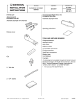
PARTS LIST
Attachment Kit
P/N 08V03-TX6-200
Accessory
Application
AUTOMATIC DAY/NIGHT
MIRROR
2013 ILX
Publications No.
BII 13533
Issue Date
MAY 2012
Automatic Day/Night Mirror Kit
P/N 08V03-TR0-100A
Automatic day/night mirror
Automatic day/night mirror harness
Operating Instructions
Harness cover
TOOLS AND SUPPLIES REQUIRED
Flat-tip screwdriver
6 Wire ties
Ratchet
10 mm Socket
Needle nose pliers
Isopropyl alcohol
Shop towel
Ruler
Clip
Diagonal cutters
Torque wrench
T20 TORX bit
Flashlight
Tape
Urethane tape
The following tools are available through the Honda Tool
and Equipment Program. On the iN, click on: Service >
Service Bay > Tool and Equipment Program, then enter
the number under “Search”. Or, call 888-424-6857.
• Trim Tool Set (T/N SOJATP2014)
• Plastic Trim Tool (T/N SILTRIMTL10)
Fuse label
© 2012 American Honda Motor Co., Inc. – All Rights Reserved.
BII 47721(1205)
08V03-TX6-2000-90
1 of 10
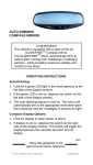
Illustration of the Automatic Day/Night Mirror in the
Vehicle
AUTOMATIC
DAY/NIGHT
MIRROR
2.
AUTOMATIC
DAY/NIGHT
MIRROR
HARNESS
Using a plastic trim tool, remove the left and right
lenses from the front roof module (two retaining tabs
for each lens). Remove two bolts.
VEHICLE
CONNECTORS
2 RETAINING
TABS
FRONT ROOF
MODULE
2 BOLTS
RIGHT LENS
2 CLIPS
2 RETAINING
TABS
2A FUSE
2 RETAINING
TABS
QA91801AH
LEFT LENS
INSTALLATION
PLASTIC TRIM TOOL
QA91802AH
Client Information: The information in this installation
instruction is intended for use only by skilled
technicians who have the proper tools, equipment, and
training to correctly and safely add equipment to your
vehicle. These procedures should not be attempted by
“do-it-yourselfers.”
1.
3.
Remove the front roof module (two clips, two
retaining tabs, and unplug the vehicle connectors).
4.
Remove the driver’s and passenger’s sunvisor
holders by turning them 45° in the counterclockwise
direction.
Disconnect the negative cable from the battery.
PASSENGER’S
SUNVISOR HOLDER
Rotate 45° in the
counterclockwise
direction.
DRIVER’S SUNVISOR
HOLDER
Rotate 45° in the
counterclockwise
direction.
2 of 10
BII 47721(1205)
QA91803AH
© 2012 American Honda Motor Co., Inc. – All Rights Reserved.
5.
Remove the rearview mirror.
6.
Base Model
•
Remove the cover (two retaining tabs).
•
While holding down the hook as shown, remove
the rearview mirror from the mirror mount.
COVER
Remove the driver’s sunvisor:
•
Pivot the left sunvisor downward.
•
Wrap tape around the tip of flat-tip screwdriver.
•
Locate the slot in the bracket cover, and insert
the flat-tip screwdriver into the slot. Push in and
hold the retaining tab.
•
While holding the retaining tab, push up on the
sunvisor and rotate it toward the door.
NOTE: If the retaining tab did not stay pushed in,
return the sunvisor to its original position and repeat
this step.
FLAT-TIP
SCREWDRIVER
REARVIEW MIRROR
Discard.
BRACKET COVER
2 RETAINING TABS
TAPE
HOOK
TAB
DRIVER’S
SUNVISOR
MIRROR
MOUNT
FRONT
Q083101AH
Non Base Model
•
Remove the TORX screw.
•
Remove the rearview mirror from the mirror
mount.
Make sure the
tab slides into
the bracket
cover.
REARVIEW MIRROR
Discard.
TORX SCREW
Remove.
Push the tab.
While pushing in
on the tab, rotate
the sunvisor
toward the door.
QA91804AH
MIRROR
MOUNT
QA32701AH
© 2012 American Honda Motor Co., Inc. – All Rights Reserved.
BII 47721(1205)
3 of 10
•
Unplug the vehicle connector, and remove the
driver’s sunvisor.
•
To prevent clips from falling into the body panel
area, carefully insert a shop towel between the
driver’s A-pillar and the driver’s A-pillar trim.
DRIVER’S
A-PILLAR TRIM
VEHICLE
CONNECTOR
DRIVER’S
A-PILLAR
DRIVER’S
SUNVISOR
Q0D0431BH
SHOP TOWEL
7.
QA01714AH
Remove the driver’s A-pillar trim.
•
Pull away the driver’s door opening seal from the
A-pillar trim.
•
Slide the driver’s A-pillar trim upward, and
remove the driver’s A-pillar trim.
•
Gently pull the A-pillar trim away from the A-pillar
to release the three clips.
•
Remove the shop towel and any clips.
Pull the clip.
UPPER CLIP
DRIVER’S A-PILLAR
DRIVER’S
A-PILLAR
TRIM
DRIVER’S
A-PILLAR
TRIM
2 CLIPS
QA91806AH
DRIVER’S DOOR
OPENING SEAL
Pull away.
4 of 10
QA91805AH
BII 47721(1205)
© 2012 American Honda Motor Co., Inc. – All Rights Reserved.
8.
Remove the remaining upper clip from the driver’s
A-pillar.
10. Pull down the left grab rail and remove two caps (four
retaining tabs).
Push two tabs.
FLAT-TIP
SCREWDRIVER
2 CLIPS
TAPE
DRIVER’S
A-PILLAR
FRONT
UPPER
CLIP
Discard.
QA91807AH
9.
LEFT GRAB
RAIL
Install the new clip (supplied) to the driver’s A-pillar
trim.
NOTE: When reinstalling the A-pillar trim, refer to the
Service Manual for the correct overlap procedure.
4 RETAINING
TABS
2 CAPS
QA01715BH
11. Using a flat-tip screwdriver wrapped with tape,
remove the left grab rail (release two clips).
12. Remove the driver’s dashboard lower cover (nine
clips, and unplug the vehicle connector).
CLIP
(supplied)
VEHICLE
CONNECTOR
DRIVER’S
A-PILLAR TRIM
Q0N0533AH
9 CLIPS
Click to Play
© 2012 American Honda Motor Co., Inc. – All Rights Reserved.
BII 47721(1205)
DRIVER’S
DASHBOARD
LOWER COVER
QA91808BH
Click to Stop
5 of 10
13. Install the automatic day/night mirror on the mirror
mount as shown, and tighten the TORX screw.
T20 TORX BIT
Torque: 1.6 - 2.0 N·m (1.2 - 1.5 lbf·ft).
Without Another Accessory Harness 6-pin connector
16. Plug the automatic day/night mirror harness 6-pin
connector into the fuse box 6-pin connector. Go to
step 18.
AUTOMATIC DAY/NIGHT
MIRROR HARNESS 6-PIN
CONNECTOR
FUSE BOX
MIRROR
MOUNT
AUTOMATIC
DAY/NIGHT
MIRROR
QA91809AH
FUSE BOX 6-PIN
CONNECTOR
14. Using isopropyl alcohol on a shop towel, thoroughly
clean the area where the fuse label will attach.
QA91811AH
With Another Accessory Harness 6-pin connector
FUSE CASE
Clean with
isopropyl alcohol.
17. If the fuse box 6-pin connector is already used by
another accessory, locate the 6-pin connector taped
to the other accessory harness. Plug the automatic
day/night mirror harness 6-pin connector into the
other accessory harness 6-pin connector.
AUTOMATIC DAY/NIGHT
MIRROR HARNESS
AUTOMATIC DAY/NIGHT
MIRROR HARNESS
6-PIN CONNECTOR
FUSE BOX
FUSE LABEL
(2A OPTION)
QA91810AH
15. Attach the fuse label to the automatic day/night
mirror harness fuse case.
OTHER ACCESSORY
HARNESS 6-PIN
CONNECTOR
QA91823AH
6 of 10
BII 47721(1205)
© 2012 American Honda Motor Co., Inc. – All Rights Reserved.
18. Secure the automatic day/night mirror harness to the
vehicle harness with two wire ties.
20. Insert the automatic day/night mirror harness
between the dashboard and the driver’s A-pillar.
AUTOMATIC DAY/
NIGHT MIRROR
DRIVER’S A-PILLAR
WIRE
TIES
VEHICLE
HARNESS
DASHBOARD
QA91812AH
19. Route the automatic day/night mirror harness toward
the outside of the vehicle as shown.
AUTOMATIC DAY/NIGHT
MIRROR HARNESS
QA91814AH
21. Align the green tape on the automatic day/night
mirror harness with the vehicle clip, and secure the
automatic day/night mirror harness to the vehicle
harness with one wire tie as shown.
DASHBOARD
VEHICLE
HARNESS
WIRE TIE
AUTOMATIC
DAY/NIGHT
MIRROR
HARNESS
VEHICLE
HARNESS
WIRE TIE
AUTOMATIC
DAY/NIGHT
MIRROR
HARNESS
AUTOMATIC
DAY/NIGHT
MIRROR
HARNESS
QA91813AH
Align.
GREEN
TAPE
© 2012 American Honda Motor Co., Inc. – All Rights Reserved.
BII 47721(1205)
VEHICLE
CLIP
QA91815AH
7 of 10
22. Secure the automatic day/night mirror harness to the
vehicle harness with three wire ties as shown.
CLIP ON SIDE
CURTAIN AIRBAG
25. Route the automatic day/night mirror harness behind
the headliner as shown. Be careful not to crease the
headliner.
CLIP ON SIDE
CURTAIN AIRBAG
Not into vehicle panel hole.
equal.
equal.
VEHICLE PANEL
HEADLINER
WIRE TIE
CLIP
HOLE
CLIP
HOLE
WIRE TIE
AUTOMATIC DAY/NIGHT
MIRROR HARNESS
VEHICLE
HARNESS
WIRE TIE
VEHICLE
HARNESS
GREEN
TAPE
AUTOMATIC
DAY/NIGHT
MIRROR
HARNESS
WIRE TIE
AUTOMATIC DAY/NIGHT
MIRROR HARNESS
QA91816BH
23. Pull the two automatic day/night mirror harness 2-pin
connectors out through the hole in the headliner as
shown. Be careful not to crease the headliner.
AUTOMATIC DAY/NIGHT MIRROR
HARNESS 2-PIN CONNECTOR
QA91818CH
26. Plug the automatic day/night mirror harness 7-pin
connector into the automatic day/night mirror.
HEADLINER
AUTOMATIC
DAY/NIGHT
MIRROR
HARNESS
7-PIN
CONNECTOR
VEHICLE 2-PIN
CONNECTOR
AUTOMATIC DAY/NIGHT
MIRROR HARNESS
2-PIN CONNECTOR
QA91817CH
24. Plug the vehicle 2-pin connector into the automatic
day/night mirror harness 2-pin connector.
AUTOMATIC
DAY/NIGHT
MIRROR
QA91819AH
8 of 10
BII 47721(1205)
© 2012 American Honda Motor Co., Inc. – All Rights Reserved.
27. Route the automatic day/night mirror harness
through the groove in the harness cover. Secure the
harness cover to the mirror stay. Slide the harness
cover behind the headliner.
30. Plug the automatic day/night mirror harness 2-pin
connector into the driver’s sunvisor 2-pin connector.
AUTOMATIC DAY/NIGHT
MIRROR HARNESS 2-PIN
CONNECTOR
HARNESS COVER
AUTOMATIC
DAY/NIGHT
MIRROR
HARNESS
AUTOMATIC
DAY/NIGHT
MIRROR STAY
HARNESS
COVER
DRIVER’S
SUNVISOR
DRIVER’S
SUNVISOR
2-PIN
CONNECTOR
QA91822AH
AUTOMATIC DAY/NIGHT MIRROR
QA91820AH
28. Using isopropyl alcohol on a shop towel, thoroughly
clean the area where the urethane tape will attach.
NOTE: Do not crease the headliner for the following
procedure.
VEHICLE PANEL
31. Reinstall the driver’s sunvisor.
32. Using needle nose pliers, remove the two clips from
the vehicle panel.
2 CLIPS
AUTOMATIC DAY/NIGHT
MIRROR HARNESS
VEHICLE PANEL
URETHANE TAPE
NEEDLE
NOSE PLIERS
HEADLINER
SECTION
VIEW
FRONT
AUTOMATIC DAY/NIGHT
MIRROR HARNESS
URETHANE
TAPE
VEHICLE
PANEL
Clean with
isopropyl
alcohol.
QA02301AH
QA91821AH
29. Secure the automatic day/night mirror harness to the
vehicle panel with one urethane tape as shown. Be
careful not to crease the headliner.
© 2012 American Honda Motor Co., Inc. – All Rights Reserved.
BII 47721(1205)
9 of 10
33. Reinstall the left grab rail with two clips. Reinstall the
caps.
FUNCTION CHECK
1.
Turn the ignition switch to ON (II), but do not start the
engine.
2 CLIPS
AUTOMATIC DAY/NIGHT MIRROR
LEFT
GRAB
RAIL
SWITCH
(Turn on.)
2 CAPS
LED
QA02302AH
34. Check that all wire harnesses are routed properly
and all connectors are plugged in.
35. Check the overlap between the headliner and the
driver’s A-pillar trim. Refer to the service manual. If
necessary, adjust the overlap.
AUTOMATIC DAY/NIGHT MIRROR
030406AB
2.
Turn on the switch. Check that the LED lights.
3.
Cover the front sensor on the automatic day/night
mirror with your hand, and use a flashlight to light the
rear sensor on the automatic day/night mirror. Make
sure the mirror surface dims.
36. Reinstall all removed parts.
37. Reconnect the negative cable to the battery and
check the operation of all lights and other electrical
accessories.
AUTOMATIC DAY/NIGHT
38. Press and hold the radio power button for two
seconds to restore the radio and navi (if equipped)
system functions.
39. Reset the clock (non-navi).
40. If the IMA battery level gauge is at zero, start the
engine and hold the rpm between 3500 and 4000 (no
load) in P or N position until the Charge/Assist meter
indicates the IMA system has stopped charging the
battery.
MIRROR
SURFACE
41. Do the Function Check.
FRONT SENSOR
Cover.
FLASHLIGHT
42. Adjust the zone and calibrate as required.
43. Put the Operating Instructions in the glove box.
REAR
SENSOR
030407AB
4.
10 of 10
BII 47721(1205)
Step on the brake pedal, and move the select lever
to the “R” position. Repeat step 3, and make sure the
mirror surface does not dim.
•
Make sure that the parking brake is set securely.
•
If the automatic day/night mirror does not
function properly, check the fuse and all
connectors.
© 2012 American Honda Motor Co., Inc. – All Rights Reserved.