1
INSTALLATION
INSTRUCTIONS
PARTS LIST
Attachment Kit
P/N 08V03-T0A-100
Accessory
Application
AUTOMATIC DAY/NIGHT
MIRROR
2012 CR-V
Publications No.
AII 12061
Issue Date
DEC 2011
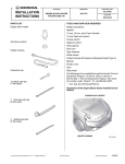
Automatic Day/Night Mirror Kit
P/N 08V03-T0A-100A
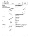
Automatic day/night mirror
Automatic day/night mirror harness
Operating Instructions
Harness cover
TOOLS AND SUPPLIES REQUIRED
Phillips screwdriver
Isopropyl alcohol
Shop towel
Fuse label
Diagonal cutters
10 mm Open end wrench
Flat-tip screwdriver
Small flat-tip screwdriver
Masking tape
Clip
T20 TORX bit
Flashlight
The following tool is available through the Honda Tool and
Equipment program. On the iN, click on: Service > Service
Bay > Tool and Equipment Program, then enter the
number under “Search.” Or call 888-424-6857.
5
Wire ties
2
EPT sealers
© 2011 American Honda Motor Co., Inc. – All Rights Reserved.
• Trim tool set (T/N SOJATP2014)
AII 46215 (1112)
08V03-T0A-1000-90
1 of 10
Illustration of the Automatic Day/Night Mirror
Installed on the Vehicle
AUTOMATIC DAY/NIGHT
MIRROR HARNESS
2.
AUTOMATIC
DAY/NIGHT
MIRROR
Remove the roof console.
•
Using a plastic trim tool, pry out and remove the
left and right lens (four retaining tabs each).
•
Open the sunglass holder and remove four
screws.
•
Remove the roof console (unplug the vehicle
connectors).
VEHICLE
CONNECTORS
2A FUSE
ROOF
CONSOLE
Q0D1415BD
SUNGLASS
HOLDER
Open.
INSTALLATION
Customer Information: The information in this
installation instruction is intended for use only by skilled
technicians who have the proper tools, equipment, and
training to correctly and safely add equipment to your
vehicle. These procedures should not be attempted by
“do-it-yourselfers.”
1.
Disconnect the negative cable from the battery.
RIGHT
LENS
4 SCREWS
LEFT
LENS
4 RETAINING
TABS
3.
4 RETAINING
TABS
Q0N2012AG
Remove the cover (two retaining tabs).
COVER
REARVIEW
MIRROR
RETAINING
TAB
HOOK
MIRROR
MOUNT
4.
2 of 10
AII 46215 (1112)
Q083101AH
While holding down the hook, remove the rearview
mirror from the mirror mount as shown.
© 2011 American Honda Motor Co., Inc. – All Rights Reserved.
5.
Release the driver’s sunvisor and passenger’s
sunvisor from the two sunvisor holders.
7.
SUNVISOR HOLDER
•
Turn the sunvisor toward the driver’s seat.
•
Locate the slot in the sunvisor holder, and insert
a flat-tip screwdriver wrapped with a masking
tape into the slot. Push in and hold the retaining
tab.
•
While holding the retaining tab, push up on the
sunvisor and rotate it toward the door.
NOTE: If the retaining tab did not stay pushed in,
return the driver’s sunvisor to its original position
and repeat the above steps.
•
Remove the driver’s sunvisor (unplug the
vehicle connector if equipped).
FLAT-TIP
SCREWDRIVER
SUNVISOR
HOLDER
Push and hold
the retaining.
FRONT
Rotate.
2 SUNVISOR
HOLDERS
6.
Remove the driver’s sunvisor.
Rotate.
Q0D1302AD
Rotate each sunvisor holders 45° counterclockwise
to remove the two sunvisor holders.
SLOT
MASKING
TAPE
VEHICLE
CONNECTOR
(if equipped)
Push and
FRONT
hold.
Rotate towards
the door.
FRONT
DRIVER’S
SUNVISOR
© 2011 American Honda Motor Co., Inc. – All Rights Reserved.
AII 46215 (1112)
Q0D1301AD
3 of 10
8.
Pull away the driver’s door opening seal, from the
driver’s A-pillar. Gently pull out the driver’s A-pillar
trim to release the clips.
10. Remove the driver’s A-pillar trim. Carefully remove
the shop towel and any clips that fell from the driver’s
A-pillar trim.
NOTE: The upper clip will stay in the body.
CLIP
DRIVER’S
A-PILLAR TRIM
Remove.
VEHICLE
PANEL
CLIP
UPPER CLIP
DRIVER’S
A-PILLAR
TRIM
DRIVER’S
A-PILLAR
TRIM
DRIVER’S
DOOR
OPENING
SEAL
Pull away.
Q0N2016AG
DRIVER’S
A-PILLAR
2 CLIPS
Q0N2014AG
9.
11. Remove the remaining upper clip from the driver’s
A-pillar.
To prevent the clips from falling into the vehicle body,
roll up the shop towel, and insert it between the
driver’s A-pillar and the dashboard. Take care not to
damage the driver’s A-pillar.
Push 2 tabs.
UPPER CLIP
Discard.
DRIVER’S
A-PILLAR
DASHBOARD
DRIVER’S
A-PILLAR
Q0N2017AG
SHOP
TOWEL
4 of 10
Q0N2015BG
AII 46215 (1112)
© 2011 American Honda Motor Co., Inc. – All Rights Reserved.
12. Remove the driver’s dashboard panel (six clips and
unplug the vehicle connector).
14. Remove the driver’s dashboard lower cover (eight
clips and unplug the vehicle connector).
VEHICLE
CONNECTOR
VEHICLE
CONNECTOR
DRIVER’S
DASHBOARD
PANEL
6 CLIPS
Q0N2019BG
DRIVER’S DASHBOARD
LOWER COVER
8 CLIPS
13. Remove the driver’s dashboard under cover (turn
the knob, one clip and one pin).
Q0N2022AG
15. Pull away the driver’s door opening seal, and
remove the driver’s dashboard side cover (two
retaining tabs, four clips and two hooks). To release
the front clip, insert a flat-tip screwdriver wrapped
with electrical tape into the dashboard hole, and
push down on the clip.
4 CLIPS
DRIVER’S DASHBOARD
SIDE COVER
DRIVER’S DOOR
OPENING SEAL
Pull away.
CLIP
KNOB
Turn.
DRIVER’S DASHBOARD
UNDER COVER
PIN
Q0N2021BG
2 HOOKS
2 RETAINING
TABS
ELECTRICAL
TAPE
© 2011 American Honda Motor Co., Inc. – All Rights Reserved.
AII 46215 (1112)
FLAT-TIP
SCREWDRIVER
HOLE
Push down on the clip.
Q0D1303CD
5 of 10
Routing the Automatic Day/Night Mirror Harness
16. Using isopropyl alcohol on a shop towel, thoroughly
clean the fuse case where the fuse label will attach.
Attach the 2A fuse label to the fuse case on the
automatic day/night mirror harness.
18. Unplug the other accessory 6-pin connector from the
fuse box, and plug the automatic day/night mirror
harness 6-pin connector into the fuse box.
FRONT VIEW
FUSE
BOX
AUTOMATIC DAY/NIGHT
MIRROR HARNESS
Plug in
here.
AUTOMATIC DAY/NIGHT
MIRROR HARNESS
6-PIN CONNECTORS
2A FUSE
LABEL
FUSE CASE
Clean with
isopropyl alcohol.
FUSE
BOX
Q0D1304BD
If the 6-pin connector is already used by another
accessory, go to step 18. Otherwise, continue with
step 17.
17. Plug the automatic day/night mirror harness 6-pin
connector into the fuse box. Go to step 20.
DUMMY CONNECTOR
Discard.
FRONT VIEW
FUSE
BOX
OTHER ACCESSORY
6-PIN CONNECTOR Q0D1414AD
19. Remove the dummy connector from the automatic
day/night mirror harness 6-pin connector, and plug
the other accessory 6-pin connector to the automatic
day/night mirror harness 6-pin connector.
Plug in
here.
FUSE
BOX
AUTOMATIC DAY/NIGHT MIRROR
HARNESS 6-PIN CONNECTOR
6 of 10
Q0D1305AD
AII 46215 (1112)
© 2011 American Honda Motor Co., Inc. – All Rights Reserved.
20. Route the automatic day/night mirror harness as
shown.
VSA SWITCH 5-PIN
CONNECTOR
23. Route the automatic day/night mirror harness up to
the driver’s A-pillar trim opening as shown.
AUTOMATIC DAY/NIGHT
MIRROR HARNESS
5-PIN CONNECTOR
DRIVER’S A-PILLAR
TRIM OPENING
DASHBOARD
AUTOMATIC
DAY/NIGHT
MIRROR
HARNESS
Q0D1403AD
AUTOMATIC DAY/NIGHT
MIRROR HARNESS
24. Route the automatic day/night mirror harness up the
A-pillar along the vehicle harness.
Q0D1401AD
21. Plug the VSA switch 5-pin connector into the
automatic day/night mirror harness 5-pin connector.
WIRE TIE
22. Secure the automatic day/night mirror harness to the
vehicle harness with two wire ties.
VEHICLE
CLIP
VEHICLE
HARNESS
VEHICLE
HARNESS
DRIVER’S
A-PILLAR
GREEN
TAPE
Align.
WIRE
TIE
AUTOMATIC DAY/NIGHT
MIRROR HARNESS
Q0D1404AD
WIRE
TIE
AUTOMATIC DAY/NIGHT
MIRROR HARNESS
© 2011 American Honda Motor Co., Inc. – All Rights Reserved.
25. Align the green tape on the automatic day/night
mirror harness with the upper vehicle clip, and
secure the automatic day/night mirror harness to the
vehicle harness with three wire ties.
Q0D1402AD
AII 46215 (1112)
7 of 10
26. Using isopropyl alcohol on a shop towel, thoroughly
clean the A-pillar where the EPT sealer will attach.
Secure the automatic day/night mirror harness to the
driver’s A-pillar with one EPT sealer.
28. Align the green tape on the automatic day/night
mirror harness with the edge of the headliner. Be
careful not to crease the headliner.
AUTOMATIC DAY/NIGHT
MIRROR HARNESS
AUTOMATIC DAY/NIGHT
MIRROR HARNESS
VEHICLE PANEL
Clean with
isopropyl alcohol.
HEADLINER
DRIVER’S A-PILLAR
Clean with
isopropyl alcohol.
GREEN TAPE
Align.
EPT SEALER
EPT SEALER
Q0D1405AD
HEADLINER
Q0D1407BD
27. Gently pull down the headliner, and tuck the
automatic day/night mirror harness under the
headliner. Be careful not to crease the headliner.
VEHICLE
PANEL
29. Using isopropyl alcohol on a shop towel, thoroughly
clean the vehicle panel where the EPT sealer will
attach. Secure the automatic day/night mirror
harness to the vehicle panel with one EPT sealer as
shown. Be careful not to crease the headliner.
AUTOMATIC DAY/NIGHT
MIRROR HARNESS
30. Install the automatic day/night mirror onto the mirror
mount, and tighten the torx screw. Torque the torx
screw to 1.8 N·m (1.3 lbf·ft).
HEADLINER
T20 TORX
WRENCH
HEADLINER
TORX
SCREW
AUTOMATIC DAY/NIGHT
MIRROR HARNESS
Q0D1406AD
MIRROR
MOUNT
AUTOMATIC DAY/
NIGHT MIRROR
8 of 10
AII 46215 (1112)
Q0D1408AD
© 2011 American Honda Motor Co., Inc. – All Rights Reserved.
31. Plug the automatic day/night mirror harness 7-pin
connector into the automatic day/night mirror.
34. Plug the automatic day/night mirror harness 5-pin
connector into the VSA switch, and reinstall the
driver’s dashboard lower cover.
AUTOMATIC DAY/NIGHT
MIRROR HARNESS 5-PIN
CONNECTOR
AUTOMATIC DAY/NIGHT
MIRROR
VSA
SWITCH
AUTOMATIC DAY/NIGHT MIRROR
HARNESS 7-PIN CONNECTOR Q0D1409AD
32. Route the automatic day/night mirror harness
through the grooves in the harness cover. Secure
the harness cover to the mirror stay as shown.
HEADLINER
AUTOMATIC
DAY/NIGHT
MIRROR
HARNESS
DRIVER’S DASHBOARD
LOWER COVER
Q0D1411AD
HARNESS
COVER
MIRROR
STAY
HARNESS
COVER
AUTOMATIC DAY/NIGHT
MIRROR
Q0D1410AD
33. Slide the harness cover inside the headliner.
© 2011 American Honda Motor Co., Inc. – All Rights Reserved.
AII 46215 (1112)
9 of 10
35. Temporarily reinstall the driver’s A-pillar trim, and
check the overlap between the headliner and the
driver’s A-pillar trim according to the service manual.
Remove the driver’s A-pillar trim. Install the new clip
(supplied) to the driver’s A-pillar trim.
Function Check
1.
Turn the ignition switch to ON (II), but do not start the
engine.
AUTOMATIC DAY/NIGHT MIRROR
NEW CLIP
DRIVER’S
A-PILLAR TRIM
(Inside)
SWITCH
Turn on.
LED
AUTOMATIC DAY/NIGHT MIRROR
Q0D1412AD
Q0N2018AG
36. Check that all wire harnesses are routed properly
and all connectors are plugged in.
2.
Turn the mirror switch on. Check that the LED glows
properly.
3.
Cover the front sensor on the automatic day/night
mirror with your hand. Using a flashlight, shine the
light on the rear sensor of the automatic day/night
mirror. Check that the mirror surface becomes dim.
37. Reinstall all removed parts.
38. Reconnect the negative cable to the battery.
AUTOMATIC DAY/NIGHT MIRROR
39. Press and hold the radio power button for two
seconds to restore the radio and navi (if equipped)
system functions.
FRONT SENSOR
Cover.
40. Reset the clock on vehicle without navigation.
MIRROR
SURFACE
NOTE:
• Check the operation of the automatic day/night mirror
according to the Operating Instructions supplied.
• Adjust the zone and calibrate as required.
41. Put the Operating Instructions in the glove box.
FLASHLIGHT
REAR SENSOR
(Inside of the mirror)
Q0D1413AD
4.
10 of 10
AII 46215 (1112)
With the parking brake properly set, step on the
brake pedal, and move the select lever to the “R”
position. Repeat step 3, and check to make sure the
mirror surface does not become dim. If the automatic
day/night mirror does not function properly, check
the fuse and all the connectors.
© 2011 American Honda Motor Co., Inc. – All Rights Reserved.