1
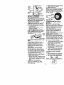
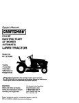
Owner's Manual
20 HP
ELECTRIC START
48" MOWER
6 SPEED TRANSAXLE
LAWN TRACTOR
Model No.
917.272230
•
•
•
•
Safety
Assembly
Operation
Maintenance
• Repair Parts
CAUTION:
Read and follow all
Safety Rules and Instructions
before operating this equipment.
For answers to your questions
about this product, Call:
1-800-659-5917
Sears Craftsman Help Line
5 am - 5 pro, Mort - Sat
Sears, Roebuck and Co., Hoffman Estates, IL 60179
V_sit our Craftsman website: www.sears.com/craftsman
Warranty ............................................... 2
Safety Rules ......................................... 3
Product Specifications .......................... 6
Assembly .............................................. 8
Operation ............................................ 13
Maintenance Schedule ...................... 19
Maintenance ....................................... 19
Service and Adjustments .................... 23
Storage ............................................... 29
Troubleshooting ................................. 30
Repair Parts ........................................ 34
Parts Ordering ..................... Back Cover
LIMITED TWO YEAR WARRANTY ON CRAFTSMAN RIDING EQUIPMENT PARTS
For two (2) years from the date of purchase, if this Craftsman Riding Equipment is
maintained, lubricated and tuned up according to the instructions in the owner's
manual, Sears will repair or replace, free of charge, any parts found to be defective in
matedal or workmanship. Warranty service is available free of charge by returning your
Craftsman riding equipment to your nearest Sears Service Center. In-home warranty
service is available but a trip charge will apply. This warranty applies only while this
product is in the United States.
This Warranty does not cover:
• Expendable items which become worn during normal use, such as blades, spark
plugs, air cleaners, belts and oil filters.
• Tire replacement or repair caused by punctures from outside objects, such as nails,
thorns, stumps, or glass.
• Repairs necessary because of operator abuse, including but not limited to, damage
caused by towing objects beyond the capability of the dding equipment, impacting
objects that bend the frame or crankshaf'_,or over speeding the engine.
• Repairs necessary because of operator negligence, including but not limited to,
electrical and mechanical damage caused by improper storage, failure to use the
proper grade and amount of engine oil, failure to keep the deck clear of flammable
debris, or the failure to maintain the equipment according to the instructionscontained in the owner's manual.
• Engine (fuel system) cleaning or repairs caused by fuel determined to be contaminated or oxidized (stale). In general, fuel should be used within thirty (30) days of its
purchase date.
• Riding equipment used for commercial or rental purposes. A product is "used for
commercial purpose" if is used for any purpose other than single family household
dwellings or in usage where profit is made.
LIMITED 90 DAY WARRANTY ON BATTERY
For ninety (90) days from date of purchase, if any battery included with this riding
equipment proves defective in material or workmanship and our testing determines the
battery will not hold a charge, Sears will replace the battery at no charge. Warranty
service is available free of charge by returning your Craftsman riding equipment to
your nearest Sears Service Center. In-home warranty service is available but a trip
charge will apply. This warranty applies only while this product is in the United States.
TO LOCATE THE NEAREST SEARS SERVICE CENTER OR TO SCHEDULE IN-HOME
WARRANTY SERVICE, SIMPLY CONTACT SEARS AT 1-800--4-MY-HOME
This Warranty gives you specific legal rights, and you may also have other rights which
may vary from state to state.
Sears, Roebuck and Co., D/817 WA, Hoffman Estates, IL 60179
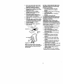
IMPORTANT:
Thiscutting
machine
iscapable
ofamputating
hands
andfeet
and
throwing objects. Failure to observe the following safety instructions could result in
sedous injury or death.
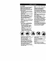
I. GENERAL OPERATION
I1. SLOPE OPERATION
• Read, understand, and follow all
Slopes are a major factor related to loss-ofinstructions in the manual and on the
control and tipover accidents, which can
machine before starting.
result in severe in ury or death. All slopes
• Only allow responsible adults, who are
require extra caut on. f you caneot back up
familiar with the instructions, to operate
the slope or if you feel uneasy on it, do not
the machine.
mow it.
• Clear the area of objects such as rocks,
DO_
toys wire, etc., which could be picked
up and thrown by the bade.
• Mow up and down slopes, not across.
• Be sure the area is clear of other
• Remove obstacles such as rocks, tree
people before mowing. Stop machine if
limbs, etc.
anyone enters the area.
• Watch for holes, ruts, or bumps.
• Never carry passengers.
Uneven terrain could overturn the
• Do not mow in reverse unless absomachine. Tall grass can hide oblutely necessary. Always leek down
stacles.
and behind before and while backing.
• Use slow speed. Choose a low gear
• Be aware of the mower discharge
so that you will not have to stop or shift
direction and do not point it at anyone.
while on the slope.
Do not operate the mower without
• Follow the manufacturer's recommeneither the entire grass catcher or the
dations for wheel weights or counterguard in place.
weights to improve stability.
• Slow down before fuming.
• Never leave a running machine
• Use extra care with grass catchers or
unattended. Always turn off blades, set
other attachments. These can change
_arking brake, stop engine, and remove
the stability of the machine.
eys before dismounting.
• Keep all movement on the slopes slow
• Tum off blades when not mowing.
and gradual Do not make sudden
• Stop engine before removing grass
changes in speed or direction.
catcher or unclogging chute.
• Avoid starting or stopping on a slope. If
• Mow only in daylight or good artificial
tires lose traction, disengage the
light.
blades and proceed slowly straight
• Do not operate the machine while
down the slope.
under the influence of alcohol or drugs.
DO NOT:
• Watch for traffic when operating near or
crossing roadways.
• Do not turn on slopes unless neces• Use extra care when loading or
sary, and then, turn sloWlyand graduunloading the machine into a trailer or
ally downhill, if possible.
truck.
• Do not mow near drep-offs, ditches, or
• Data indicates that operators, age 60
embankments. The mower could
i/aearsand above, are involved in a
suddenly turn over if a wheel is over
rge percentage of dding mowerthe edge of a cliffor ditch,or if an edge
related injudes. These ol_erators
caves in.
should evaluate their abihty to operate
• De not mow on wet grass. Reduced
the dding mower safely enough to
traction could cause sliding.
protect themselves and others from
• Do not try to stabilize the machine by
serious injury.
putting your foot on the ground.
• Keep machine free of grass, leaves or
other debris build-up which can touch
• Do not use grass catcher on steep
hot exhaust / engine parts and bum.
slopes.
Do not allow the mower deck to plow
leaves or other debris which can cause
build-up to occur. Clean any oil or fuel
spillage before operating or stodng the
machine. Allow machine to cool before
storage.
•
III.CHILDREN
Tragic
accidents
canoccuriftheoperator •
isnetalerttothepresence
ofchildren.
Children
areoftenattracted
tothe
machine
and the mowing activity. Never
•
assume that chitdren will remain where
you last saw them.
• Keep children out of the mowing area
and under the watchful care of another
responsible adult.
• Be alert and rum machine off if children
enter the area.
• Before and when backing, look behind
and down for small children.
• Never carry children. They may fall off
and be sedously injured or interfere
with safe machine operation.
• Never allow children to operate the
machine.
• Use extra care when approaching blind
comers, shrubs, trees, or other objects
that may obscure vision.
•
IV. SERVICE
• Use extra care in handling gasoline
and other fuels. They are flammable
and vapors are explosive.
-Use only an approved container.
-Never remove gas cap or add fuel
with the engine running. Allow
engine to cool before refueling. Do
not smoke.
-Never refuel the machine indoors.
- Never store the machine or fuel
container inside where there is an
open flame, such as a water heater.
• Be sure the area is clear of other
people before mowing. Stop machine if
anyone enters the area.
• Never carry passengers or children
even with the blades off.
• Do not mow in reverse unless absolutely necessary. Always look down
and behind before and while backing.
• Never carry children. They may fall off
and be seriously injured or interfere
with safe machine operation.
• Keep children out of the mowing area
and under the watchful care of another
responsible adult.
4
•
•
•
•
•
Never run a machine inside a clo_
area.
Keep nuts and bolts, especially bl
attachment belts, tight and keep
equipment in good condition.
Never tamper with safety devices.
Check their proper operation regl
Keep machine free of grass, leaw
other debds build-up. Clean oil o
spillage. Allow machine to cool I_
stodng.
Stop and inspect the equipment if
strike an cbjoct. Repair, if necass=
before restarting.
Never make adjustments or repair
with the engine running.
Grass catcher components are su
to wear, damage, and detedoratio
which could expose moving parts
allow objects to be thrown. Frequ
check components and replace w
manufacturer's recommended par
wt3en necessary.
Mower blades are sharp and can
Wrap the blade(s) or wear gloves,
use extra caution when servicing
Check brake operation frequently
Adjust and service as required.
• Be alert and turn machine off if ch
enter the area.
• Before and when backing, look I_
and down for small children.
• Mow up and down slopes (15 ° M_
not across.
• Remove obstacles such as rocks,
limbs, etc.
• Watch for holes, ruts, orbumps.
Uneven terrain could overturn the
machine. Tall grass can hide obsl
• Useslowspeed.
Choose
a lowgearso
thatyouwillnothavetostoporshift
whileontheslope.
ACAUTION: Tow only the attachments
that are recommended by and comply
with specificationsof the manufacturer of
your tractor. Use common sense when
towing. Operate only at the lowest
possible speed when on a slope. Too
heavy of a !oad, while on a slope, is
dangerous. Tires can lose traction with
the ground and cause you to lose control
of your tractor.
AWARNING: Engine exhaust some of its
const tuents, and certa n veh cle components contain or emit chemicals known to
the State of California to cause cancer
and birth defects or other reproductive
harm.
• Avoid starting or stopping on a slope. If
tires lose traction, disengage the
blades and proceed slowly straight
down the slope.
• If machine stops while going uphill,
disengage blades, shift into reverse
and back down slowly.
• Do not turn on slopes unless necessary, and then, turn slowly and gradually downhill, if possible.
ALook for this symbol to point out
important safety precautions. It means
CAUTIONI!! BECOMEALERT!!T YOUR
SAFETY IS INVOLVED.
A_.CAUTION: In order to prevent accidental starting when setting up, transporting, adjusting or making repairs,
always disconnect spark plug wire and
place wire where it cannot contact spark
plug.
_kCAUTION: Do not coast down a hill in
neutral, you may lose control of the
tractor.
A,WARNING: Battery posts terminals
and re ated accessories conta n sad and
lead compounds, chemicals known to the
State of California to cause cancer and
birth defects or other reproductive harm.
Wash hands after handling.
5
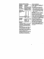
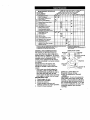
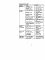
PRODUCT
SPECIFICATIONS
REPAIR AGREEMENT
GASOLINE 3.5GALLONS
A Repair Agreement is available on this
CAPACITY UNLEADED
product. Contact your nearest Sears
ANDTYPE: REGULAR
store for details.
OILTYPE
SAE
10W30
(above
32°F) CUSTOMER RESPONSIBILITIES
(PI-SF-SJ): SAE
5W-30
(below
32°F) • Read and observe the safety rules.
OIL CAPACITY:
SPARK PLUG:
GAP: .030")
GROUND SPEED
(MPH):
W/FILTER: 4.5 PINTS
W/OFILTER: 4.0 PINTS
CHAMPION RC12YC
• Follow a regular schedule in maintaining, cadng for and using your tractor.
• Follow the instructions under "Maintenance" and "Storage" sections of this
owner's manual.
_.WARNING: This tractor is equipped
with an internal combustion engine and
should not be used on or near any
unimproved forest-cevered, brashcovered or grass-covered land unless the
engine's exhaust system is equipped with
a spark arrester meeting applicable local
or state laws (if any). If a spark an'ester is
used, it should be maintained in effective
working order by the operator.
In the state of California the above is
required by law (Section 4442 of the
California Public Resources Cede).
Other states may have similar laws.
Federal laws apply on federal lands. A
spark attester for the muffler is available
through your nearest Sears service
center. (See REPAIR PARTS section of
this manual).
1st
1.2
2nd
1.5
3rd
2.4
4th
3.5
5th
4.8
6th
5.3
REVERSE: 1.5
TIRE PRESSURE:FRONT: 14 PSI
REAR: 10 PSI
CHARGING
SYSTEM:
15 AMPS @ 3600 RPM
BATTERY:
AMP/HR:
30
MIN. CCA: 240
CASE SIZE: U 1R
BLADE BOLT
45-55 FT. LBS.
TORQUE:
CONGRATULATIONS on your purchase
of a new tractor. It has been designed,
engineered and manufactured to give
you the best possible dependability and
performance.
Should you expedenca any problem you
cannot easily remedy, please contact
your nearest Sears or other qualified
service center. We have competent, welltrained technicians and the proper tools
to service or repair this tractor.
Please read and retain this manual. The
instructionswill enable you to assemble
and maintain your tractor properly.
Always observe the "SAFETY RULES'.
6
Steering
Wheel
Steenng
Wheel
Insert
Steenng Sleeve
Seat
Mower
(5) Retainer Spdngs
(double loop) - _
'
"_'_J
(1) Washer
17/32 x 1-3/16 x 12
_'
(1) Knob_
(1)Front Plate
_
(2)Flanged
v(::_
Gauge
Pins
(2) Retainer Spnngs (single loop)
(4) Shoulder Bolt
_
,_
(4) Retainer Springs
(double loop)
(4) Clevis Pins
(4)Wheels
(4) Locknut 3/8-16
(2) Locknuts 5/16-18
--
_l
_1_._
I
IIIIIIIIIIlllllllhlllil/
=
(2)Hex Bolts 5/16-18 x 1
I
Cassette
""_
Key
Nose Roller
.o,,er
N_cekets
(2) Washers
17/32 x 7/8 x 16 Ga.
Slope Sheet
For Future Use
'
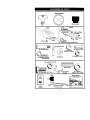
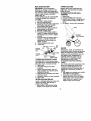
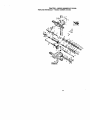
Yournewtractor
hasbeenassembled
atthefactory
with exception of those parts left
unassembled for shipping purposes. To ensure safe and proper operation of your
tractor all parts and hardware you assemble must be tightened securely Use the
correct tools as necessary to Insure proper tightness Review the video cassette before
you begin.
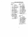
TOOLS REQUIRED FOR ASSEMBLY
A socket wrench set will make assembly
easier Standard wrench sizes you need
are hsted below.
(1) 9/16" Wrench (1) 3/4" Socket w/
(1) 1/2" wrench
ddve ratchet
(1) Utility knife
(1) Pliers
(1) Tire pressure gauge
When nght or left hand is mentioned in
this manual, It means, from your point of
view, when you are in the operating
position (seated behind the steering
wheel).
TO REMOVETRACTOR
FROM
CARTON
UNPACK CARTON
1. Remove all accessible loose parts
and parts boxes from shipping carton.
2 Cut, from top to bottom, along lines on
all four comers of shipping carton, and
lay panels fiat.
3 Remove mower and package matenals.
4 Check for any additional loose parts
or boxes and remove.
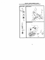
BEFORE REMOVING TRACTOR
FROM SKID
ATTACH STEERING WHEEL
1. Remove lock nut and large fiat washer
from steenng shaft
2 Position front wheels of the tractor so
they are pointing straight forward
3. Slide the steering sleeve over the
steering shaft.
4. Position steering wheel so cross bars
are honzontal (left to nght) and slide
onto steedng wheel adapter
5 Secure steering wheel to steedng
shaft with lock nut and large fiat
washer previously removed Tighten
securely.
6 Snap steedng wheel insert into center
of steering wheel.
7. Remove protective materials from
tractor heed and grill
IMPORTANT: Check for and remove any
staples in skid that may puncture tires
where tractor is to roll off skid
SteenngWheel
I_
_nsert Lock Nut
_
fF_-_-._
SteenngWheel'_
Washer
_/
Seer ng
Shaft_.
_
Stee,,n,,.
Sleeve
Adaptor
t .',-_._- "."
=_._.< -'_",.1','.
,...
,, ,,,
-L_' ,,'. t !.
,,
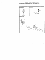
HOWTO SET UPYOURTRACTOR
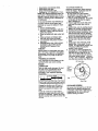
CHECK BATTERY
1, Lift heed to raised position,
NOTE: If thisbattery is put into service
after month and year indicated on label
(label located between terminals) charge
battery for minimum of one hour at 6-10
amps. (See "BATTERY" In MAINTENANCE section of this manual for
charging instruchons)
Label
INSTALL SEAT
Adjust seat before tightening adjustment
knob
1. Remove adjustment knob and fiat
washer securing seat to cardboard
packing and set aside for assembly of
seat to tractor
2. Pivotseatupward
andremove
from
thecardboard
packingRemove
the
cardboard
packing
anddiscard.
3. Place
seatonseatpansoheadof
shoulder
bolt =spositioned over large
slotted hole in pan.
4. Push down on seat to engage
shoulder bolt in slot and pull seat
towards rear of tractor.
5. Pivot seat and pan forward and
assemble adjustment knob and flat
washer loosely Do not tighten
6. Lower seat into operating position and
sit In seat
7. Slide seat until a comfortable position
is reached which allows you to press
clutch/brake pedal all the way down.
8 Get off seat without moving its
adjusted position.
9. Raise seat and tighten adlustment
knob securely.
Seat
ShOulder
Bolt
Flat Washer
NOTE: You may now roll or dnve your
tractor off the skid. Follow the appropriate
Instructionbelow to remove the tractor
from the skid.
TO ROLLTRACTOR
OFF SKID (See
Operation section for location and
function of controls)
1. Press lift lever plunger and raise
attachment lift lever to its highest
position.
2. Release parking brake by depressing
clutch/brake pedal
3 Place gearshift lever in neutral (N)
position.
4. Roll tractor forward off skid
TO DRIVETRACTOR
OFF SKID (See
Operation section for location and
function of controls)
_WARNING:
Before starting read,
understand and fo ow a nstructions m
the Operation section of thB manual. Be
sure tractor is In a well-vent=!atedarea. Be
sure the area m front of tractor _sclear of
other people and objects
1. Be sure all the above assembly steps
have been completed,
2. Check engine oil level and fill fuel
tank with gasoline.
3. Sit on seat m operating position,
depress clutch/brake pedal and set
the parking brake
4. Place gear shift lever =n neutral (N)
position.
5. Press hftlever plunger and raise
attachment lif_lever to its h=ghest
position.
6 Start the engine. After engine has
started, move throttle control to idle
position
7. Depress clutch/brake pedal into full
"BRAKE" poslbon and hold Move
gearshift lever to 1st gear.
8. Slowly release clutch/brake pedal and
slowlydrive tractor off skid.
9 Apply brake to stop tractor, set parking
brake and place gearsh=ftlever in
neutral position.
10.Turn =gn=t=on
key to "OFF" pos=tlon
Continue with the mstrections that follow.
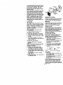
ASSEMBLE
GAUGEWHEELSTO
MOWER
DECK
Thegauge
wheels
are designed to keep
the mower deck in proper position when
operating mower. Be sure they are
propedy adjusted to ensure optimum
mower performance.
1 Shde gauge wheel bar down into
bracket channel, Be sure that gauge
wheel bar aligning holes are on top.
Assemble gauge wheels as shown
using shoulder bolts, 3/8 washers and
3/8-16 center Iocknuts and tighten
securely.
2. For ease of mower to tractor assembly, raise gauge wheels to highest
pes=Uonand retain with clevis pins
and spnng retainers
NOTE: Adjust gauge wheels before
operating mower, See =TO ADJUST
GAUGE WHEELS" in the Operation
section of this manual
P,n-_
Nose Roller
-_'_'_
//j
_'_
,
_
Lock .
/ Nut
B"Bracket
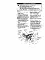
INSTALL MOWER AND DRIVE BELT
Be suretractoris ce level surfeceand mower
suspensionarms are raisedwith attachment
liftconbol.Engage parkingbrake.
1 Cut and remove ties secudng antisway bar and belts. Swmg anti-sway
bar to left side of mower deck.
2 Slide mower under tractor with
deflector shield to dght side of tractor
IMPORTANT: Check belt for proper
routing in all mower pulley grooves.
3, If equipped,turn height adjustment
knob counterclockwise until It stops,
4 Lower mower linkage with attachment
lift control
5. Be sure belt tension rod Is in disengaged pes_tton.
6. Install belt into electdc clutch pulley
Retainer
Spnng
\
///_F.
groove.
3/8 Washer
3/8-16
7. Place the suspenston arms on
outward pointing deck ptns. Retam
with double loop retainer spring with
loops up as shown
8. Install front plate assembly to tractor
suspension brackets and retatn with
single loop retainer spnngs as shown
Center
Locknut
TO ATTACH NOSE ROLLER
1. Position brackets, 17/32 x 7/8 x 16
gauge washers, and nose roller
between deck mounting brackets as
shown. Be sure to position brackets
on correct side, as shown
2 install hex belts and lock nuts as
shown. Tighten hardware securely
NOTE: Be sure bracket tabs are positioned in tab holes in deck brackets
10
9. Position
front
plate assembly between
front mower brackets. Raise deck and
plate assembly to align holes and
insert flanged pins. Secure pins with
double loop retainer spdngs between
the plate assembly and mower
brackets.
NOTE: To assist in locating hole in
flanged pin, the hole in pin is inline with
notch on head of pin.
IMPORTANT: Check belt for proper
routing in all mower pulley grooves.
10.Engage belt tension red by pushing
rod into locking bracket.
CAUTION: Belt tension red is spdng
loaded, Have a tight gdp on rod and
engage slowly.
11, Connect anti-sway bar to chassis
bracket under left footrest and retain
with double loop retainer spring,
12.If equipped, turn height adjustment
knob clockwise to remove slack from
mower suspension.
13. Raise deck to highest position,
14.Adjust gauge wheels before operating
mower as shown in the Operation
section of this manual.
Belt Tension Rod
Disengaged Position
CHECK TIRE PRESSURE
The tires on your tractorwere ovednflated
at the factory for shippingpurposes.
Correct tire pressure is importantfor best
cutting performance.
• Reduce tire pressure to PSI shown in
"PRODUCT SPECIFICATIONS" section
of thismanual.
CHECK MOWER LEVELNESS
For best cutting results,mower shouldbe
properly leveled. See "TO LEVEL MOWER
HOUSING" in the Service and Adjustments
section of this manual.
CHECK FOR PROPER POSITION OF ALL
BELTS
See the figures that are shown for replacing motion, mower drive, and mower blade
drive belts in the Service and Adjustments
section of this manual. Verifythat the belts
are routed correctly.
CHECK BRAKE SYSTEM
After you learn how to operate your tractor,
check to see that the brake is propedy
adjusted. Sea =TOADJUST BRAKE"in the
Service and Adjustmentssection of this
manual.
Lock Bracket
Electdc Clutch
Pulley\
\
Front
Chassis
\Brackets
Mower \
Bracket\
Bracket_
Front
Suspention
Front
Assembly
Plate
,Loop Retainer
Gauge
Wheel
Single
Loop
Retainer
Springs
Double Loop
Retainer
Spring
RETALNERSPRINGS
USE PLIERS FOR I
Anti-Sway
Bar
Suspension Arms
Double Loop
Retainer Spring
(Outward pointing
deck pins)
Deflector Sheild
11
=/CHECKLIST
Before you operate and enjoy your new
tractor, we wish to assure that you receive
the best performance and satisfaction
from this quality product.
Please review the following checklist:
,/ All assembly instructions have boon
completed.
,/No remaining loose parts in carton.
,/' Battery is propedy prepared and
cberged.(Minimum 1 hour at 6 amps).
4" Seat is adjusted comfortably and
tightened securely.
4" All tires are propedy inflated. (For
shipping purposes, the tires were
ovednflated at the factory).
/' Be sure mower deck is propedy leveled
side-tc--sideifront-to-rearfor best cutting
results. (Tires must be propedy inflated
for leveling).
4 Check mower and drive belts. Be sure
they are routed propedy around pulleys
and inside all belt keepers.
•/ Check widng. See that all connections
are still secure and wires are properly
clamped.
While learning how to use your tractor,
pay extra attention to the following
important items:
J Engine oil is at proper level.
4 Fuel tank is filled with fresh, clean,
regular unleaded gasoline.
,/Become familiar with all controls - their
location and function. Operate them
before you start the engine.
4 Be sure brake system is in safe
operating condition.
12
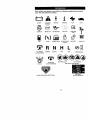
These
symbols
mayappear
onyourtractor
orinliterature
supplied
withtheproduct.
Learnandunderstand
theirmeaning.
BATTERY
CAUTION OR
WARNING
REVERSE
FORWARD
FAST
SLOW
ENG,NEON
ENO,NEGrE
O,LPRESSURE
UOHTSON
O%'_MP T
4"
FUEL
CHOKE
MOWER HEIGHT
PARKING BRAKE
LOCKED
UNLOCKED
MOWER LIFT
R N H L
ATTACHMENT
CLUTCH ENGAGED
IGNITION
REVERSE
NEUTRAL
ATTACHMENT
CLUTCH DISENGAGED
HIGH
LOW
KEEP AREA CLEAR
PARKING BRAKE
SLOPE HAZARDS
(SEE SAFETY RULES SECTION)
FREE WHEEL
(Automatic Modelsonly)
DANGER, KEEP HANDS AND FEET AWAY
13
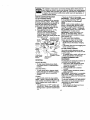
KNOWYOURTRACTOR
READ
THISOWNER'S
MANUAL
ANDSAFETY
RULES
BEFORE
OPERATING
YOUR
TRACTOR
Compare
theillustrations
withyourtractor
tofamiliarize
yourseff
withthelocations
of
vadous
controls
andadjustments.
Savethismanual
forfuturereference.
Ammeter
Hourmeter
it Switch
PcsitJon
Attachment
Clutch Switch
Plunger
Attachment
Clutch/Brake
Lever
Our tractors conform to the safety standards of the Amedcan
National Standards Institute.
ATTACHMENT CLUTCH SWITCH: Used
to engage the mower blades, or other
attachments mounted to your tractor.
LIGHT SWITCH: Turnsthe headlights on
and off.
THROTTLE CONTROL - Used to control
engine speed.
CHOKE CONTROL - Used when starting
a cold engine.
CLUTCH/BRAKE PEDAL: Used for
declutchiag and braking the tractor and
starting the engine.
GEARSHIFT LEVER - Selects the speed
and direction of tractor.
ATTACHMENTLIFT LEVER - Usedto raise,
lower,andadjustthe mowerdeckor other
attachmentsmountedto yourtractor.
LIFT LEVER PLUNGER: Used to release
attachment lift lever when changing its
position.
IGNITION SWITCH: Used for startingand
stopping the engine.
AMMETER: Indicates battery charging (+)
or discharging (-).
PARKING BRAKE: Locks clutch/breke
into the brake position.
HOURMETER - Indicateshoursof operation.
14
i
Theoperation
ofanytractor
canresult
inforeign
objects
thrown
intothe I
eyes, which can result in severe eye damage. Always wear safety glasses I
or eye shields while operating your tractor or performing any adjustments
or repairs. We recommend a wide vision safety mask over spectacles, or
standard safety g asses.
HOWTO USEYOURTRACTOR
TO SET PARKING BRAKE
Your tractor is equipped with an operator
presence sensing switch. When engine
is running, any attempt by the operator to
leave the seat withoutfirst setting the
parking brake will shut off the engine.
1. Depress clutch/brake pedal into full
"BRAKE" position and hold.
2. Place parking brake lever in "ENGAGED" position and release
pressure from clutch/brake pedal.
Pedal should remain in "BRAKE"
position, Make sure parking brake will
hold tractor secure.
Push-In to
Attachment Clutch
Choke "Disengage ' SwitchPullOutTo
• Never use choke to stop engine.
IMPORTANT: Leaving the ignition switch
in any position other than "OFF" will
cause the battery to be discharged,
(dead).
NOTE: Under eartain cunditions when
tractor is standing idle with the engine
running, hot engine exhaust gases may
cause "browning" of grass. To eliminate
this possibility,always stop engine when
stopping tractor on grass areas.
ACAUTION: Always stop tractorcompletely, as describ_l above, before
leaving the operator's position; to empty
grass catcher, etc.
TO USE THROTTLE CONTROL
Always operate engine at full throttle.
• Operating engine at less than full
throttle reduces the battery charging
rate.
Control
• Full throttle offers the best bagging and
mower performance.
"Brake"
Key
Lever
TO USE CHOKE CONTROL
Use choke control whenever you are
P ition o
__
\Ignition GearShift starting a cold engine. Do not use to start
a warm engine.
"_ParkingBra_e
• To engage choke control, pull knob out.
Clutch/Brake
"Engaged"Position
Slowly push knob in to disengage,
Pedal=Drive"
"Disengaged"
TO
MOVE FORWARD AND
Position
Position
BACKWARD
STOPPING
The direction and speed of movement is
controlled by the gearshift lever.
MOWER BLADES 1. Start tractor with clutch/brake pedal
• To stop mower blades,move attachdepressed and gearshift lever in
ment clutch switch to "DISENGAGED"
neutral (N) position.
position,
2, Move gearshift lever to desired
GROUND DRIVE position.
• To stop ground drive, depress clutch/
3. Slowly release clutch/brake pedal to
start movement.
brake pedal into full "BRAKE" position.
• Move gearshift lever to neutral (N)
IMPORTANT: Bring tractor to a complete
position.
stop before shifting or changing gears.
Failure to do so will shorten the useful life
ENGINE of your transaxle.
• Move throttle control to slow position.
TO ADJUST MOWER CUTTING HEIGHT
NOTE: Failure to move throttle control to
slow position and allowing engine to idle
The position of the attachment lift lever
before stopping may cause engine to
determines the cutting height.
"backfire".
• Grasp lift lever.
• Turn ignition key to "OFF" position and
• Press plunger with thumb and move
remove key. Always remove key when
lever to desired position.
leaving tractor to prevent unauthorized
use,
15
Thecuttingheightrangeis approximately
1-1/2
to 4".Theheights
are
measured from the ground to the blade
tip with the engine not running. These
heights are approximate and may vary
depending upon soil conditions, height of
grass and types of grass being mowed.
• The average lawn should be cut to
approximately 2-1/2 inches during the
cool season and to over 3 inches
during hot months. For healthier and
better looking lawns, mow often and
after moderate growth.
• For best cutting performance, grass
over 6 inches in height should be
mowed twice, Make the first cut
relatively high; the second to desired
height.
TO ADJUST GAUGE WHEELS
Gauge wheels are properly adjusted
when they are slightly off the ground
when mower is at the desired cutting
height in operating position. Gauge
wheels then keep the deck in proper
position to help prevent scalping in most
terrain conditions.
NOTE: Be sure tractor is on a fiat level
surface.
1. Lower mower and adjust mower to
desired cutting height.
2. Remove retainer spring and clevis pin
which secure each gauge wheel bar.
3. Lower gauge wheels to ground. Raise
gauge wheels slightly to align holes in
bracket and gauge wheel bar and
insert clevis pin. Gauge wheels
should be slightly off the ground.
4. Replace retainer spring into clevis pin.
5. Besure all gauge wheels are in the
same setting.
IMPORTANT: Be sure to readjust gauge
wheels if you change the cutting height
of the mower deck.
Retainer
Sprin
•_,::'
1. Select desired height of cut.
2. Start mower blades by engaging
attachment clutch control.
TO STOP MOWER BLADES disengage attachment clutch control.
_CAUTION:
Do not operate the mower
without either the entire grass catcher, on
mowers so equipped, or the deflector
shield in place.
AttachmentClutch
SwitchPullOutTo
=Engage"
AttachmentLiftLever
HighPosition
/
;?
Po_i_on
:/ .;'.,.--_Low
- _
Deflector
• I _"
TO OPERATE
Shield
ON HILLS
£_CAUTION: Do not drive up or down
hills with slopes greater than 15° and do
not drive across any slope.
• Choose the slowest speed before
starting up or down hills.
• Avoid stopping or changing speed on
hills.
• if slowing is necessary, move throttle
control lever to slower position.
• If stopping is absolutely necessary,
push clutch/brake pedal quickly to
brake position and engage parking
brake.
• Move gearshift lever to 1st gear. Be
sure you have allowed room for tractor
to roll slightly as you restart movement.
• To restart movement, slowly release
parking brake and clutch/brake pedal.
• Make all turns slowly.
TOTRANSPORT
Clevis
Pin
TO OPERATE MOWER
Your tractor is equipped with an operator
presence sensing switch. Any attempt by
the operator to leave the seat with the
engine running and the attachment clutch
engaged will shut off the engine.
16
• Raise attachment lift to highest position
with attachment lift control.
• When pushing or towing your _actor,
be sure gearshift lever is in neutral (N)
position.
• Do not push or tow tractor at more than
five (5) MPH.
NOTE: To protect hood from damage
when transporting your tractor on a truck
or a trailer, be sure hood is closed and
secured to tractor. Use an appropriate
means of tying hood to tractor (rope, cord,
etc.).
TOWING
CARTS
ANDOTHER
ATTACH-ACAUTION: Fill to bottom of gas tank
MENTS
filler neck. Do not overfill. Wipe off any
spilled oil or fuel. Do not store, spill or use
Towonlytheattachments
thatare
gasoline near an open flame.
recommended
byandcomply
with
specifications
ofthe manufacturer of your TO START ENGINE
tractor. Use common sense when towing.
Too heavy of a load, while on a slope, is
dangerous. Tires can lose traction with
the ground end cause you to lose control
of your tractor.
BEFORE STARTING THE ENGINE
CHECK ENGINE OIL LEVEL
The engine in your tractor has been
shipped, from the factory, already filled
with summer weight oil.
1. Check engine oil with tractor on level
ground.
2. Unthread and remove oil fill cap/
dipstick; wipe oil off. Reinsert the
dipstick into the tube and rest oil fill
cap on the tube. Do not thread the
cap onto the tube. Remove and read
oil level. If necessary, add oil until
"FULL" mark on dipstickis reached.
Do not overfill.
• For cold weather operation you should
change oilfor easier starting(See "OIL
VISCOSITY CHART" in the Maintenanca section of thismanual).
• To change engine oil, see the Maintenance section in this manual.
ADD GASOLINE
• Fill fuel tank. Use fresh, clean, regular
unleaded gasoline with a minimum of
87 octane. (Use of leaded gasoline will
increase carbon and lead oxide
deposits and reduce valve life). Do not
mix oil with gasoline. Purchase fuel in
quantities that can be used within 30
days to assure fuel freshness.
IMPORTANT: When operating in temperatures below 32°F(0°C), use fresh,
clean winter grade gasoline to help
insure good cold weather starting.
_ILWARNING: Experience indicates that
alcohol blended fuels (called gasohol or
using ethanol or methanol) can attract
moisture which leads to separation and
formation of acids during storage. Acidic
gas can damage the fuel system of an
engine while in storage. To avoid engine
problems, the fuel system should be
emptied before storage of 30 days or
longer. Drain the gas tank, start the
engine and let it run until the fuel lines
and carburetor are empty. Use fresh fuel
next season. See Storage Instructionsfor
additional information. Never use engine
or carburetor cleaner products in the fuel
tank or permanent damage may occur.
When starting the engine for the first time
or if the engine has run out of fuel, it will
take extra cranking time to move fuel from
the tank to the engine.
1. Sit on seat in operating position,
depress clutch/breke pedal and set
parking brake.
2. Place gear shift lever in neutral (N)
position.
3. Move attachment clutch to =DISENGAGED" position.
4. Move throttle control to fast position
5. Pull choke control out for a cold
engine start attempt. For a warm
engine start attempt the choke control
may not be needed.
NOTE: Before starting, read the warm and
cold starting procedures below.
6. Insert key into ignition and turn key
clockwise to START" position and
release key as soon as engine starts.
Do not run starter continuouslyfor
more than fifteen seconds per minute.
If the engine does not start after
several attempts, push choke control
in, wait a few minutes and try again. If
engine still does not start, pull the
choke control out and retry.
WARM WEATHER STARTING (50° F and
above)
7. When engine starts, slowly push
choke control in until the engine
begins to run smoothly. If the engine
starts to run roughly, pull the choke
control out slightly for a few seconds
and then continue to push the control
in slowly.
• The attachments and ground drive can
now be used. If the engine does not
accept the load, restart the engine and
allow it to warm up for one minute
using the choke as described above,
COLDWEATHER STARTING (50 ° F and
below)
7. When engine starts, slowly push
choke control in until the engine
begins to run smoothly. Continue to
push the choke control in small steps
allowing the engine to accept small
changes in speed and load, until the
choke control is fully in. If the engine
starts to run roughly, pullthe choke
control out slightlyfor a few seconds
and then continue to push the control
in slowly. This may require an engine
warm-up period from several seconds
to several minutes, depending on the
f7
temperature.
• Theattachments
canbeusedduring
theengine
warm-up
pedod
andmay
require
thechokecontrol
be pulled out
slightly,
NOTE: ffat a highaltitude(above 3000 feet)
or in coldt_res
(below 32 F) 61e
carburetorfuel mixturemay need to be
a_tmted for best engine perfom_nce, See
"To ADJUST CARBURETOR" in the Service
and Adjuatn_ntssec_on of thismanual.
MOWlNGTIPS
• Mower should be propedy leveled for
best mowing performance. See =TO
LEVEL MOWER HOUSING" in the
Service and Adjustments section of this
manual.
• The left hand side of mower should be
used for trimming.
• Ddve so that clippings are discharged
onto the area that has been cut. Have
the cut area to the dght of the tractor.
This will result in a more even distdbution of clippings and more uniform
cutting.
• When mowing large areas, start by
turning to the dght so that clippings will
discharge away from shrubs, fences,
ddveways, etc. After one or two rounds,
mow in the opposite direction making
left hand turns until finished.
• If grass is extremely tall, it shouldbe
mowed twice to reduce load and
possible fire hazard from dded clippings. Make first cut relatively high; the
second to the desired height.
• Do not mow grass when it is wet. Wet
grass will plug mower and leave
undesirable clumps. Allow grass to dry
before mowing.
• Always operate engine at full throtUe
when mowing to assure better mowing
performance and proper discharge of
material. Regulate ground speed by
selecting a low enough gear to give the
mower the best cutting performance as
well as the quality of cut desired.
• When operating attachments, select a
ground speed that will suit the terrain
and give best performance of the
attachment being used.
18
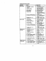
MAINTENANCE
SCHEDULE
REGULAR SERVICE
c_
em_ op_io_
check
Tire
Pressure
CheCk Operator _
T Int_
T)_ _
_
i,_" __s"
sysv_s
and
tJ
V
It##
_1
_
_ _/_J
_'/_
/
Che_
CA
Sharpen/Rop4_ce
T
0
Lub_oo
Chart
Check Batte,7 Level
I_
I, /
R
Clean B.attefy and Tefm,rals
_
It##
Ched(
T_n
If
Adjust
Bk_de Belt(s) Tension
Mower
V*
Bl_bd_
_r+
_s
Drive B*dt(s) Ter_ion
CIWPCk Engine
Cd Level
V'
_4
F=la_e CoOling
Adjust Mobon
Change
FaSteners
_,_s
_
Engine O1{
_2_
E
clean r&JrFilth*
tl_z
N
Clean
_2
G
Inspect Muff_r/spa_ Am_ter
i_
Rep_
E
Cle_n Engine C(;o_ing Fins
I_/;z
Re_
_2
Air
_n
C311
F_lte_
t_ /
prequipped)
_.2
Air Filte_ Paper Cartridge
Replace Fuel Filter
1
2+
3.
4.
DATES !
IV#
R
for LOOse
SERVICE
11_
O_a_gem_e_wh_l_per_dJ_Juod_'ah_,*yk_d_'lnNghamt_lt_r,
S_o
r _ro o#_ _h_l
operat_g _ d_ly o( _
condone.
# _q_pped ,_lh _4 _K_, d,ange _ _
50 hours
p.*_zco U_d_s moro often _he, mo_ng in _andy r._4.
lp_um=
5
6
7
tfequ_ppedW_lad_sl_biesystem
N_t r_q_d
if _q_pp_
w4_ rn_nt enar_hee
bat;e_y
_ghtm _1
_ude _vot t)_t _o 35 ft._t>r_ ma._m.
C¢ no( _,_erl gh_m.
LUBRICATION CHART
GENERAL RECOMMENDATIONS
The warranty on this tractor does not
cover items that have been subjected to
operator abuse or negligence. To receive
full value from the warranty, operator must
maintain tractor as instructed in this
manual. Some adjustments will need to
be made pedodically to propedy maintain
your tractor.
All adjustments in the Service and
Adjustments section of this manual
should be checked at least once each
season.
• Once a year you should replace the
spark plug, clean or replace air filter,
and check blades and belts for wear. A
new spark plug and clean air filter
assure proper air-fuel mixture and help
your engine run better and last longer.
BEFORE EACH USE
1. Check engine oil level.
2. Check brake operation.
3. Check tire pressure.
4. Check operator presence and
intedock systems for proper operation.
5. Check for loose fasteners.
_) Spindle-_-I_F'--Spindle(_
Zerk
,_=dl
I1_ Zerk
¢_)Front ._+
++
-+
-+=+"
_+i '_Front Wheel (_
Wheel
_'_J
__ ,_ Bearing
Bearing ,_ _ +=_--,:_ zerk
Zerks :,
',"-;-
_I
-_-:
Pivots
(_SAE 30 or 10w30 Motor Oil
(_General Purpose Grease
(_Refer to Maintenance "ENGINE"
Section
IMPORTANT: Do not oil or grease the
pivot points which have special nylon
bearings. Viscous lubricantswill attract
dust and dirt that will shorten the life of
the self-lubricatingbeadngs. If you feel
they must be lubricated, use only a dry,
powdered graphite type lubricant
sparingly.
19
TRACTOR
IMPORTANT: To ensure proper assembly,
center hole in blade must align with star
on mandrel assembly.
4. Reassemble hex belt, lock washer
and flat washer in exact order as
shown.
5. Tighten bolt securely (45-55 Ft. Lbs.
torque).
IMPORTANT: Blade bolt is Grade 8 heat
treated,
Always observe safety rules when
performing any maintenance.
BRAKE OPERATION
If tractor requires more than six (6) feet
stopping distance at high speed _n
highest gear, then brake must be adjusted. (See "TO ADJUST BRAKE" in the
Service and Adjustments section of this
manual),
TrailingEdge Up
TIRES
Mandrel
• Maintain proper air pressure in all tires
FLatWasher_._
^
(See "PRODUCT SPECIFICATIONS"
section of this manual).
Lock
"__
Center Hole
• Keep tires free of gasoline, oil, or insect
Washer"_,.
_._
_. _ _
Blade
control chemicals which can harm
_Hex
Bo_t(,Grade8)
Ribber.
• Avoid stumps, stones, deep ruts, sharp
*A Grade 8 heat treatedboltcan be
objects and other hazards that may
identifiedby sixlineson the bolt head.
cause tire damage.
TO SHARPEN BLADE
NOTE: To seal tire punctures and prevent
NOTE: We do not recommend sharpenfiat tires due to slow leaks, tire sealant
ing blade, but if you do, be sure the blade
may be purchased from your local parts
is balanced.
dealer. Tire sealant also prevents tire dry
Care should be taken to keep the blade
rot and corrosion.
balanced. An unbalanced blade will
OPERATOR PRESENCE SYSTEM
cause excessive vibration and eventual
damage to mower and engine.
Be sure that operator presence and
• The blade can be sharpened with a file
interlocksystems are working properly. If
your tractor does not function as deor on a gdnding wheel. Do not attempt
to sharpen while it is on the mower.
scribed below, repair the problem
• To check blade balance, you will need
immediately.
• The engine should not start unless the
a 5/8" diameter steel bolt, pin, or a cone
clutchlbrake pedal is fully depressed
balancer. (When using a cone baland attachment clutch control is in the
ancer, follow the instructions supplied
with balancer).
disengaged position.
• When the engine is running, any
NOTE: Do not use a nail for balancing
blade. The lobes of the center hole may
attempt by the operator to leave the
seat without first setting the parking
appear to be centered, but are not,
• Slide blade onto an unthreaded portion
brake should shut off the engine.
of the steel bolt or pin and hold the bolt
• When the engine is running and the
or pin parallel with the ground. If blade
attachment clutch is engaged, any
is balanced, it should remain ina
attempt by the opera(or to leave the
horizontal position. If either end of the
seat should shut off the engine.
blade moves downward, sharpen the
• The attachment clutch should never
heavy end until the blade is balanced.
operate unless the operator is in the
Center Hole
seat.
BLADE CARE
For best results mower blades must he
Blade
kept sharp. Replace bent or damaged
5/8" Bolt or Pinblades.
BLADE REMOVAL
1. Raise mower to highest position to
BA'B'ERY
allow access to blades.
Your tractor has a battery charging
2. Remove hex bolt, lock washer and fiat
system which is sufficientfor normal use.
washer secudng blade.
However, periodic charging of the battery
3, Install new or resharpened blade with
with an automotive charger will extend its
trailing edge up towards deck as
shown,
2 0 life.
• Keep battery and terminals clean.
• Keep battery bolts tight.
• Keep small vent holes open.
• Recharge at 6-10 amperes for 1 hour.
NOTE: The odginal equipment battery on
your tractor is maintenance free, Do not
attempt to open or remove caps or covers.
Adding or checking level of electrolyte is
not necessary.
TO CLEAN BATTERY AND TERMINALS
Corrosion and dirt on the battery and
terminals can cause the battery to =leak"
power.
1. Remove terminal guard.
2. Disconnect BLACK battery cable first
then RED battery cable and remove
battery from tractor.
3. Rinse the battery with plain water and
dry.
4. Clean terminals and battery cable
ends with wire brush until bdght.
5. Coat terminals with grease or petroleum jelly.
6. Reinstall battery (See =REPLACING
BATrERY" in the SERVICE AND
ADJUSTMENTS section of this
manual).
V-BELTS
Check V-baits for deterioration and wear
after 100 hours of operation and replace
if necessary. The belts are not adjustable.
Replace belts if they begin to slip from
wear.
TRANSAXLE COOLING
Keep transaxle free from build-up of dirt
and chaff which can restrict cooling.
ENGINE
LUBRICATION
Only use high quality detergent oil rated
with API service classification SF-SJ.
Select the oil's SAE viscosity grade
according to your expected operating
temperature.
SAE VL_30_'rY
GRi_
TO CHANGE ENGINE OIL
Determine temperature range expected
before oil change. All oil must meet API
service classification SF-SJ.
• Be sure tractor is on level surface.
• Oil will drain more freely when warm.
• Catch oil in a suitable container.
1. Remove oil fill cap/dipstick. Be careful
not to allow dirt to enter the engine
when changing oil.
2. Remove cap from end of drain valve
and install the drain tuba onto the
fitting.
3. Unlock drain valve by pushing inward
slightly and turning counterclockwise.
4. To open, pull out on the drain valve.
5. After oil has drained completely, close
and lock the drain valve by pushing
inward and turning clockwise until the
pin is in the locked position as shown.
6. Remove the drain tube and replace
the cap onto to the end of the drain
valve.
7. Refill engine with oil through oil fill
dipsticktube. Pour slowly. Do not
overfill. For approximate capacity see
"PRODUCT SPECIFICATIONS"
section of this manual.
8. Use gauge on oil fill cap/dipstickfor
checking level. Insert dipstick into the
tube and rest the oil fill cap on the
tuba. Do not thread the cap onto the
tube when taking reading. Keep oil
at =FULL" line on dipstick. Tighten cap
onto the tube securely when finished.
Oil Drain Valve
Closed
and
Locked
posi_on
F.,S
Cap
Drain Tube
Change the oil after every 50 hours of
CLEAN AIR SCREEN
operation or at least once a year if the
Air screen must be kept free of dirt and
tractor is not used for 50 hours in one
chaff to prevent engine damage from
year.
overheating. Clean with a wire brush or
Check the crankcase oil level before
compressed air to remove dirt and
starting the engine and after each eight
stubborn dded gum fibers.
(8) hours of operation. Tighten oil fill cap/
dipsticksecurely each time you check the
oil level.
21
CLEAN
AIRINTAKEICOOLING
AREAS
Toinsureproper
coeling,
makesurethe
grassscreen,
cooling
fins,andother
external
surfaces
oftheengine
arekept
deanatalltimes.
Every100hours
ofoperation
(moreoften
underextremely
dusty,
dirtyconditions),
remove the blower housing and other
cooling shrouds. Clean the cooling fins
and external surfaces as necessary. Make
sure the coelmg shrouds are reinstalled.
NOTE: Operating the engine with a
blocked grass screen, dirty or plugged
cooling fins, and/_" cooling shrouds
removed will cause engine damage due
to overheating.
AIR FILTER
Your engine will not run properly using a
dirty air tilter. Clean the foam pre-cleaner
after every 25 hours of operation or every
season. Service paper cartridge every
100 hours of operation or every season,
whichever occurs first.
Service air cleaner more often under
dusty conditions.
1. Loosen knob and remove cover.
TO SERVICE PRE-CLEANER
2. Slide foam pre-cleaner off cartridge.
3. Wash It in liquid detergent and water.
4. Squeeze it dry in a clean cloth. Allow
it to dry.
5. Saturate it in engine oil, Wrap it in
clean, absorbent cloth and squeeze to
remove excess oil.
TO SERVICE CARTRIDGE
• Replace a dirty, bent, or damaged
cartridge.
NOTE: Do not wash the paper cartridge
or use pressurized air, as this will
damage the cartridge,
6. Remove nut and cartddge plate.
7. Reinstall the pre-cleaner (cleaned
and oiled) over the paper cartridge.
8. Check rubber seal for damage and
proper position around stud. Replace
if necessary.
9. Reassemble air cleaner, cartridge
plate, and out.
10. Reinstall air cleaner cover and secure
by tightening knob.
Cartridge
Foam
Rubber
Seal
Knob
ge
Plate
ENGINE OIL FILTER
Replace the engine oil filter every season
or every other oil change if the tractor is
used more than 100 hours in one year.
MUFFLER
Inspect and replace corroded muffler and
spark attester (if equipped) as it could
create a fire hazard and]or damage.
SPARK PLUGS
Replace spark plugs at the beginning of
each mowing season or after every 100
hours of operation, whichever occursfirst.
Spark plug type and gap setting are
shown in "PRODUCT SPECIFICATIONS"
section of this manual.
IN-LINE FUEL FILTER
The fuel filter should be replaced once
each season. If fuel filter becomes
clogged, obstructing fuel flow to carburetor, replacement is required.
1. With engine cool, remove filter and
plug fuel line sections.
2. Place new fuel filter in position in fuel
line with arrow pointing towards
carburetor.
3. Be sure there ere no fuel line leeks
and damps are properly positioned.
4. Immediately wipe up any spilled
gasoline.
Clam
lamp
I Filter
CLEANING
• Clean engine, battery, seat, finish, etc,
of all foreign matter.
• Keep finished surfaces and wheels free
of all gasoline, oil, etc.
• Protect painted surfaces with automotive type wax.
We do not recommend using a garden
hose to clean your tractor unless the
electrical system, muffler,air tilter and
carburetor are covered to keep water out.
Water in engine can result in s shortened
22engine life.
CAUTION:
BEFORE
PERFORMING
ANYSERVICE
ORADJUSTMENTS:
1.Depress
clutch/brake
pedal
fullyandsetparking
brake,
Place
gearshift
lever in neutral (N) position.
3.
4.
5.
6.
Place attachment clutch in "DISENGAGED" position,
Turn ignition key "OFF" and remove key,
Make sure the blades and all moving parts have completely stopped.
Disconnect spark plug wire from spark plug and place wire where it cannot
come in contact with plug.
TRACTOR
TO REMOVE MOWER
1. Place attachment clutch in "DISENGAGED" position.
2. If equipped, turn height adjustment
knob to lowest setting.
3. Lower mower to its lowest position.
4. Disengage belt tension rod from lock
bracket.
CAUTION: Rod is spdng loaded. Have
a tight grip on rod and release slowly.
5. Remove retainer spring holding antiswaybar to chassis bracket and
disengage anti-swaybar from bracket.
6. Remove four retainer spdngs from
front plate assembly and remove
plate.
7. Remove retainer spdngs from
suspension arms at deck and disengage arms from deck.
8. Raise attachment lift to its highest
position.
9. Slide mower forward and remove belt
from electric clutch pulley.
10.Slide mower out from under dght side
of tractor.
TO INSTALL MOWER
Follow procedure described in =INSTALL
MOWER AND DRIVE BELT"in the
Assembly section of this manual.
TO LEVEL MOWER HOUSING
Adjust the mower while tractor is parked
on level ground or driveway. Make sure
tires are propedy inflated (See =PRODUCT SPECIFICATIONS" section of this
manual). If tires are over or
undednflatsd, you wiBnot properly adjust
your mower.
SIDE-TO-SIDE ADJUSTMENT
• Raise mower to its highest position.
• At the midpoint of both sides of mower,
measure height from bottom edge of
mower to ground. Distance "A" on
both sides of mower should be the
same or within 1/4" of each other.
• If adjustment is necessary, make
adjustment on one side of mower only.
• To raise one side of mower, tighten lift
link adjustment nut on that side.
• To lower one side of mower, loosen lift
link adjustment nut on that side.
Electric
Clutch Pulley
Suspension
BeltTension
Rod
(Disengaged_j,
Position)
/z"
Front Mower
Bracket
Front
I_ate
Chassis
Retainer Springs
(Both Sides)
Retainer
:rant Mower
Anti-Sway
Bar
23
Bottom
Edge
of
Mower
toGround
\
Bottom
Edge
of
Mower
toGround
/
BOTH FRONT LINKS MUST BE EQUAL
IN LENGTH
Nut "E"
A_SUspensi°n
Adjustment
Lift Link
Nut
Assembly_
NOTE: Each full turn of adjustment nut
will change mower height about 1/8".
• Recheck measurements after adjusting.
FRONT-TO-BACK ADJUSTMENT
IMPORTANT: Deck must be level side-toside.If the following front-to-back adjustment is necessary, be sure to adjust both
front linksequally so mower will stay
level side-to-side.
To obtain the best cutting results, the
mower housing should be adjusted so
that the front is approximately 1/8" to 1/2"
lower than the rear when the mower is in
its highest position.
Check adjustment on right side of tractor.
Measure distance =D" directly in front and
behind the mandrel at bottom edge of
mower housing as shown.
• Before making any necessary adjustments, check that both front linksare
equal in length.
• If links are not equal in length, adjust
one link to same length as other link.
• To lower front of mower loosen nut "E"
on both front links an equal number of
turns.
• When distance =D" is 1/8" to 1/2" lower
at front than rear, tighten nuts =F"
against trunnion on beth front links.
• To raise front of mower, loosen nut "F"
from trunnion on both front links.
Tighten nut "E" on beth front linksan
equal number of turns.
• When distance "D"is 1/8" to 1/2" lower
at front than rear, tighten nut "F" against
trunnion on both front links.
• Recheck side-to-side adjustment.
TO REPLACE MOWER DRIVE BELT
MOWER DRIVE BELT REMOVAL
1. Park tractor on a level surface.
Engage parking brake.
2. Lower mower to its lowest position.
3. Disengage belt tension rod from lock
bracket.
24
K_aCAUTION: Rod is spring loaded.
vea nrm grip on roa an release slowly.
4. Remove screws from R,H. mandrel
cover and remove cover.
5. Remove any dirt or grass clippings
which may have accumulated around
mandrels and entire upper deck
surface.
6. Disconnect R.H. suspension arm from
rear deck bracket by removing
retainer spring.
7. Carefully roll belt over the top of R.H.
mandrel pulley.
8. Remove belt from electric clutch
pulley.
9. Remove belt from idler pulleys.
10.Check primary idler arm and two
idlers to see that they rotate freely.
11.Be sure spdng is securely hooked to
primary idler arm and spdng arm.
MOWER DRIVE BELT INSTALLATION
12. Install belt in both idlers.
13.Install new belt onto electdc clutch
pulley.
14.Carefully roll belt into upper groove of
R.H. mandrel pulley.
15. Carefully check belt routing making
sure belt is in the grooves correctly.
16.Reconnect R.H. suspension arm to
rear deck bracket with retainer spring.
17.Reassemble R.H. mandrel cover.
18.Engage belt tension rod by pushing
rod into locking bracket.
BeltTension
Rod
(Disengaged
R.H,
position) Mandrel
E}ectf.,c Clutch
£
- Idler
Pulleys
Sprin
Arm
R.H,
Arm
PrimaryIdler
TO REPLACE MOWER BLADE DRIVE
BELT
Park the tractor on level surface. Engage
parking brake.
1. Remove mower drive belt (See "TO
REPLACE MOWER DRWE BELT" in
thissection of thismanual),
2. Remove mower (Sou "TO REMOVE
MOWER" in thissection of this manual).
3. Remove screws from L.H. mandrel
cover and remove cover.
4. Carefullyroll belt off L.H. mandrel
pulley.
5. Remove belt from center mandrel
pulley, idler pulley,and R.H. mandrel
pulley.
6. Remove any dirt or grass which may
have accumulated around mandrels
and entire upper deck surface.
7. Check secondary idler arm and idler
pulley to see that they rotatefreely,
8. Be sure springis hooked in secondary
idler arm and secondary spdng arm.
9. Install new belt in tower groove of R,H.
mandrel pulley, idler pulley, and center
mandrel pulley as shown.
10.Carefully roll belt over L.H. mandrel
pulley. Make sure belt is in all grooves
properly.
11,Relestall L.H. mandrel cover.
12. Reinstallmower to tractor (See
=INSTALL MOWER AND DRIVE BELT"
in the Assembly section of this manual).
13.Reassemble mower ddve belt (See
"TO REPLACE MOWER DRIVE BELT"
in this section of this manual).
LH,
Idler Arm
TO ADJUST BRAKE
Your tractor is equipped with an adjustable
brake system which is mounted on the
side of the transaxle.
fftractor requiresmore than six (6) feet
stoppingdistance at high speed in
highest gear on a level dry concrete or
paved surface, then brake must be
adjusted.
1. Depress clutch/brake pedal and
engage parking brake.
2, Measure distance between brake
operating arm and nut "A"on brake
rod.
3, ff distance is other than 1-1/2", loosen
jam nut and turn nut "A"untildistance
becomes 1-1/2". Retighten jam nut
against nut =A".
4. Road test tractorfor proper stopping
distance as stated above, Readjust if
necessary, if stopping distanceis still
greater than six (6) lout in highest gear,
further maintenance is necessary.
Contact a Sears or other qualified
service center.
WITH PARKING
BRAKE "ENGAGED"
Nut _A"
m Nut
Operating
Arm
TO REPLACE MOTION DRIVE BELT
Park the tractor on level surface. Engage
parking brake. For assistance, there is a
belt installation guide decal on bottom
side of left footrest.
1. Remove mower (Sou "TO REMOVE
MOWER" in this section of this
manual.)
2. Disconnect clutch wire harness.
3. Remove clutch ideator.
4. Remove belt from stationary idler and
clutching idler.
5, Pull belt slack toward rear of tractor.
Remove belt upwards from transaxle
pulley by deflecting belt keepers.
6. Pull belt toward front of tractor and
remove downwards from around
electric clutch.
7. Install new belt by reversing above
procedure.
i Arm
Mandrel
Pulley
R.H.
Mandrel
25
4. Replace washers and snap retaining
dng securely in axle groove.
5. Replace axle cover.
NOTE: To seal tire punctures and prevent
fiat tires due to slow leaks, tire sealant
may be purchased from your local parts
dealer. Tire sealant also prevents tire dry
rot and corrosion.
Electric
Clutch
Clutching /
Idler
Stationae//
Idler
Transaxle---_,
Pulley
_
-- Clut_
Clutch
Wire
Washers
RetainingRing _k
TRANSAXLE GEAR SHIFT LEVER
NEUTRAL ADJUSTMENT
The transaxle should be in neutral when
the gear shift lever is in neutral (N) (lock
gate) position•The adjustment is preset at
the factory; however, if adjustment is
needed, proceed as follows:
1. Make sure transaxle is in neutral (N).
NOTE: When the tractor rear wheels
move freely, the transaxle is in neutral.
2. Loosen adjustment bolt in front of the
dght rear wheel.
3. Position the gear shift lever in the
neutral (N) position.
4. Tighten adjustment bolt securely.
NOTE: If additional clearance is needed
to get to adjustment bolt, move mower
deck height to the lowest position.
GearshiftLever
Neutral
•
_ustment
Gate
Bolt
TO ADJUST STEERING WHEEL ALIGNMENT
If steedng wheel crossbars are not
horizontal (l_'t to dght) when wheels are
positioned straight forward, remove
steering wheel and reassemble per
instructionsin the Assembly section of
this manual.
FRONT WHEEL TOE-INICAMBER
The front wheel toe-in and camber are
not adjustable on your tractor. If damage
has occurred to affect the front wheel toein or camber, contact your nearest Sears
or other qualified service center•
TO REMOVEWHEEL
FOR REPAIRS
1. Block up axle securely.
2. Remove axle cover, retaining ring and
washers to allow wheel removal (rear
wheel contains a square key - Do not
lose).
3. Repair tire and reassemble•
NOTE: On rear wheels only: align
grooves in rear wheel hub and axle.
Insert square key.
Cove
Axle r___J
Square Key (Rear ,=,_-' "_X
_w
Wheel Only)
TO START ENGINEWlTH AWEAK
BATI'ERY
_-=CAUTION: Lead-acid batteries
generate explosive gases. Keep sparks,
flame and smoking materials away from
bettedes. Always wear eye protection
when around batteries.
If your battery is too weak to start the
engine, it should be recharged. (See
"BATTERY" in the MAINTENANCE
section of this manual).
If =jumper cables" are used for emergency
starting, follow this procedure:
IMPORTANT: Your tractor is equipped
with a 12 volt negative grounded system.
The other vehical must also be a 12 volt
negative grounded system, Do not use
your tractor battery to start other vehicles.
TO ATTACH JUMPER CABLES 1. Connect each end of the RED cable to
the POSITIVE (+) terminal of each
battery, taking care not to short
against chassis.
2. Connect one end of the BLACK cable
to the NEGATIVE (-) terminal of fully
charged battery.
3. Connect the other end of the BLACK
cable to good CHASSIS GROUND,
away from fuel tank and battery.
TO REMOVE CABLES, REVERSE
ORDER 1. BLACK cable first from chassis and
then from the fully charged battery.
2. RED cable last from both batteries.
"Positive" (+,__"Negative"
26
(-)
REPLACING BA'FrERY
_CAUTION:
Do not short battery
terminals by allowing a wrench or any
other object to contact beth terminals at
the same time. Before connecting battery,
remove metal bracelets, wristwatch
bands, dngs, etc.
Positive terminal must be connected first
to prevent sparking from accidental
grounding.
1. Lift hood to raised position.
2. Remove terminal guard.
3. Disconnect BLACK battery cable then
RED battery cable and carefully
remove battery from tractor.
4. Install new battery with terminals in
same position as old battery.
5. Reinstall terminal guard.
6. First connect RED battery cable to
positive (+) battery terminal with hex
bolt and keps nut as shown. Tighten
securely.
7. Connect BLACK grounding cable to
negative (-) battery terminal with
remaining hex belt and keps nut.
Tighten securely
8. Close terminal access doors.
9. Close hood.
Terminal
_;
Keps
r_ut/"_*,------.-__BoltHex
,Nut
.. -_
.......
Door
' "....
Access
"_e
Terminal
Guard__qB_ca_i_;
Cable
(Red)
Negativeable
TO REPLACE HEADLIGHT LAMP
CAUTION: When lit, the halogen lamps
get extremely hot. Hold lamp assembly by
the holder and do not touch the bulb.
1. Raise hood.
2. Disconnect harness from lamp
assembly.
3. Rotate counterclockwise and pull
lamp assembly out of the hole in the
backside of the gdll.
4, Insert new lamp assembly and rotate
clockwise to lock.
5. Reconnect harness to lamp assembly.
6. Close hood.
INTERLOCKS AND RELAYS
Loose or damaged wiring may cause your
tractorto run pnerly,stop running, or
prevent it from starting.
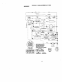
• Check wiring. See electrical wiring
diagram in the Repair Parts section.
TO REPLACE FUSE
Replace with 20 amp automofive-type
plug-in fuse. The fuse holder is located
behind the dash.
TO REMOVE HOOD AND GRILL
ASSEMBLY
1. Raise hood.
2. Unsnap headlight wire connector.
3. Stand in front of tractor. Grasp hood at
sides, tilt toward engine and lift off of
tractor.
4. To re )lace, reverse above procedure.
nector
ENGINE
Maintenance, repair, or replacement of
the emission control devices and systems,
which are being done at the customers
expense, may be performed by any nonroad engine repair establishment or
individual. Warranty repairs must be
performed by an authorized engine
manufacturer's service outlet.
TO ADJUST THROTTLE CONTROL
CABLE
The throttle control has been preset at the
factory and adjustment should not be
necessary. Check adjustment as described below before loosening cable. If
adjustment is necessary, proceed as
follows:
1. With engine not nJnning,move throttle
control lever to fast position.
2. Check that speed control lever is
against stop screw. If it is not, loosen
casing clamp screw and pull throttle
cable until lever is against screw.
Tighten clamp screw securely.
27
Idle Fuel Adjusting
Needle
Idle Speed
Adjusting
Screw
Throttle
Control
;hoke
TO ADJUST CHOKE CONTROL
The choke control has been preset at the
factory and adjustment should not be
necessary, check adjustment as descdbed below before loosening cable, If
adjustment is necessary, proceed as
follows:
1, With engine not running, move choke
control (located on dash panel) to full
choke position.
2. Remove air cleaner cover, filter and
cartddge plate to expose carburetor
choke (See =AIR FILTER" in the
Maintenance section of this manual),
3. Choke should be closed. If it is nat,
loosen casing clamp screw and move
choke cable until choke is completely
closed. Tighten casing clamp screw
securely.
4. Reassemble air cleaner,
Closed
Full Choke
TO ADJUST CARBURETOR
The carburetor has been present at the
factory and adjustment should not be
necessary. However, minor adjustment
may be required to compensate for
differences in fuel, temperature, altitude
or load. If the carburetor does need
adjustment, proceed as follows:
In general, fuming the adjusting needles
in (clockwise) decreases the supply of
fuel to the engine giving a leaner fuel/air
mixture. Turning the adjusting needles out
(counterclockwise) increases the supply
of fuel to the engine giving a richer fuel/
air mixture.
IMPORTANT: Damage to the needles
and the seats in carburetor may result if
screw is fumed in tee fight.
PRELIMINARY SETTING1. Be sure you have a clean air filter, and
the throttle control cable is adjusted
propedy (see =TO ADJUST
THROTTLE CONTROL CABLE" in the
Service and Adjustments section of
this manual).
2. With engine off turn idle fuel adjusting
needle in (clockwise) closing it finger
tight and then turn out (counterclockwise) 1 turn.
FINAL SETTING 1. Start engine and allow to warm for five
minutes. Make final adjustments with
engine running and shiflJmotion
control lever in neutral (N) position.
NOTE: The high idle is set at the factory
and cannot be adjusted.
2. Idle seeed setting - With throttle
control lever in slow position,engine
should idle at 1200 RPM. If engine
idles too slow or fast, tum idle speed
adjusting screw in or out until correct
idle is attained.
3. Idle fuel needle setting - With throttle
control lever in slow position, turn idle
fuel adjusting needle In (clockwise)
until engine speed decreases and
then turn out (counterclockwise)
approximately 3/4 turn to obtain the
best low speed performance.
4. Recheck idle speed. Readjust if
necessary.
ACCELERATION TEST 5. Move throttle control lever from slow to
fast position. If engine hesitates or
dies, turn idle fuel adjusting needle
out (counterclockwise) 1/8 turn.
Repeat test and continueto adjust, if
necessary, until engine accelerates
smoothly.
High speed stop is factory adjusted. Do
not adjust-damage may result.
IMPORTANT: Never tamper with the
engine governor, which is factory set for
proper engine speed. Overspeeding the
engine above the factory high speed
settingcan be dangerous. If you think the
engine-governed high speed needs
adjusting, contact a Sears or other qualified
service center, which has proper equipment and expadence to make any
necessary adjustments.
28
Immediately prepare your tractor for
storage at the end of the season or if the
tractor will not be used for 30 days or
more.
• kCAUTION: Never store the tractor with
gasoline in the tank inside a building
where fumes may reach an open flame or
spark. Allow the engine to cool before
stodng in any enclosure.
TRACTOR
Remove mower from tractor for winter
storage. When mower is to be stored for
a period of time, clean it thoroughly,
remove all dirt, grease, leaves, etc. Store
in a clean, dry area.
1. Clean entire tractor (See =CLEANING"
in the Maintenance section of this
manual).
2. Inspect and replace belts, if necessary
(See belt replacement instructions in
the Service and Adjustments section
of this manual).
3. Lubdcate as shown in the Maintenance section of this manual.
4. Be sure that all nuts, bolts and screws
are securely fastened. Inspect moving
parts for damage, breakage and wear.
Replace if necessary.
5. Touch up all rusted or chipped paint
surfaces; sand lightly before painting.
BATTERY
• Fully charge the battery for storage.
• After a period of time in storage, battery
may require recharging.
• To help prevent corrosion and power
leakage dudng long periods of storage,
battery cables should be disconnected
and battery cleaned thoroughly (see
"TO CLEAN BATTERY AND TERMINALS" in the Maintenance section of
this manual).
• After cleaning, leave cables disconnected and place cables where they
cannot come in contact with battery
terminals.
• If battery is removed from tractorfor
storage, do not store battery directly on
concrete or damp surfaces,
ENGINE
FUEL SYSTEM
IMPORTANT: It is important to prevent
gum depesites from forming in essential
fuel system parts such as carburetor, fuel
hose, or tank dudng storage. Also,
expedance indicates that alcohol
blended fuels (called gasohol or using
ethanol or methanol) can attract moisture
which leads to separation and fonT_ation
of acids during storage. Acidic gas can
damage the fuel system of and engine
while in storage.
1. Drain the fuel tank.
2. Start the engine and let it run until the
fuel lines and carburetor are empty.
• Never use engine or carburetor cleaner
products in the fuel tank or permanent
damage may occur.
• Use fresh fuel next season.
NOTE: Fuel stabilizer is an acceptable
alternative in minimizing the formation of
fuel gum deposits dudng storage. Add
stabilizer to gasoline in fuel tank or
storage container. Always follow the mix
ratio found on stabilizer container. Run
engine at least 10 minutes after adding
stabilizer to allow the stabilizer to reach
the carburetor. Do not drain the gas tank
and carburetor if using fuel stabilizer.
ENGINE OIL
Drain oil (with engine warm) and replace
with clean engine oil. (See "ENGINE" in
the Maintenance section of this manual).
CYLINDER(S)
1. Remove spark plug(s).
2. Pour one ounce of oil through spark
plug hole(s) into cylinder(s).
3. Tum ignition key to "START" position
for a few seconds to distributeoil.
4. Replace with new spark plug(s).
OTHER
• Do not store gasoline from one season
to another.
• Replace your gasoline can if your can
starts to rust. Rust and/or dirt in your
gasoline will cause problems.
• If possible, store your tractor indoors
and cover it to give protection from dust
and dirt.
• Cover your tractor with a suitable
protective cover that does not retain
moisture. Do not use plastic. Plastic
cannot breathe which allows condensation to form and will cause your
tractor to rust.
IMPORTANT: Never covet tractor while
engine and exhaust areas are still warm.
29
TROUBLESHOOTING CHART
PROBLEM
CAUSE
Will not start
1, Out of fuel.
2. Engine not "CHOKED"
properly.
3, Engine flooded.
CORRECTION
Hard to start
1. Dirty air filter.
2. Bad spark plug.
3. Weak or dead battery.
1. Fill fuel tank.
2. See "TO START ENGINE"
in Operation section,
3. Wait several minutes
before attempting to start.
4. Bad spark plug.
4, Replace spark plug.
5. Dirty air filter.
5, Clean/replace air filter.
6. Dirty fuel filter.
6. Replace fuel fi[ter,
7 Water in fuel.
7. Drain fuel tank and
carburetor, refill tank with
fresh gasoline and replace
fuel filter.
8. Loose or damaged wiring.
8. Check all widng.
9. Carburetor out of adjustment. 9. See "To Adjust Carburetor"
in Service Adjustments
section,
10.Contact a Sears or other
10.Engine valves out of
adjustment.
qualified service center.
4. Dirty fuel filter.
5. Stale or dirty fuel.
6. Loose or damaged wiring.
7. Carburetor out of adjustment.
8. Engine valves out of
adjustment.
Englnewillnot
turn over
; 1. Clutch/brake pedal not
depressed.
2. Attachment clutch is
engaged.
3, Weak or dead battery.
9. Faulty operator presence
swithch(es).
1. Depress clutch/brake
pedal.
2. Disengage attachment
clutch.
3, Recharge or replace
battery.
4. Replace fuse.
5. Clean battery terminals.
6, Check all widng.
7. Check/replace ignition
switch.
8, Check/replace solenoid or
starter.
9. Contact a Sears or other
qualified service center.
1.
2,
3.
4.
1.
2.
3.
4.
4.
5,
6.
7.
Blown fuse.
Corroded battery terminals.
Loose or damaged widng.
Faulty ignition switch.
8, Faulty solenoid or starter.
Engine clicks but
will not start
1. Clean/replace air filter.
2. Replace spark plug.
3. Recharge or replace
battery.
4. Replace fuel filter.
5. Drain fuel tank and refill
with fresh gasoline.
6. Check all widng.
7. See "To Adjust Carburetor"
in Service Adjustments
section.
8. Contact a Sears or other
qualified service center..
Weak or dead battery.
Corroded battery terminals.
Loose or damaged wiring.
Faulty solenoid or starter.
3O
Recharge or replace battery
Clean battery terminals.
Check all wiring.
Check/replace solenoid or
starter.
TROUBLESHOOTING
CHART
PROBLEM
CAUSE
CORRECTION
Lossofpower 1. Cutting
toomuch
grass/too1. Set in "Higher Cut" position/
fast.
reduce speed.
2. Throttle
in=CHOKE"
2. Adjust throttle control.
position.
3. Build-up of grass, leaves
and trash under mower.
4. Dirty air filter.
5. Low oil level/dirty oil.
6. Faulty spark plug.
7. Dirty fuel filter,
8. Stale or dirtyfuel.
9. Water in fuel.
10.Spark plug wire loose.
11. Dirty engine air screen/fins.
12. Dirty/clogged muffler,
13.Loose or damaged widng+
14.Carburetor out of
adjustment.
15.Engine valves out of
adjustment.
Excessive
vlbratlon
1. Worn. bent or loose blade.
2. Bent blade mandrel.
3. Loose/damaged part(s).
Engine
continues1.
torun
whenoperator
leavesseat
withattachment
clutchengaged
Poorcut-uneven1.
3. Clean underside of mower
housing.
4. Clean/replace air filter.
5. Check oil level/change oil.
6. Clean and regap or change
spark plug.
7. Replace fuel filter.
8. Drain fuel tank and refill witt
fresh gasoline.
9, Drain fuel tank and carburetor, refill tank with fresh
gasoline and replace fuel
filter.
10.Connect and tighten spark
plug wire.
11.Clean engine air screen/fins
12. Clean/replace muffler.
13.Check all widng.
14. See "To Adjust Carburetor"
in Service Adjustments
section.
15.Contact a Sears or other
qualified service center.
1. Replace blade.
Tighten blade bolt.
2. Replace blade mandrel.
3. Tighten loose part(s).
Replace damaged parts.
Faulty operator-safety
presence control system.
1. Check wiring, switches and
connections. If not
corrected, contact a
Sears or other qualified
service center.
Worn. bent or loose blade.
1. Replace blade. Tighten
blade bolt.
2. Level mower deck.
3. Clean underside of mower
housing.
4. Replace blade mandrel.
5. Clean around mandrels to
open vent holes.
2. Mower deck not level.
3. Buildup of grass, leaves.
and trash under mower.
4. Bent blade mandrel.
5. Clogged mower deck vent
holes from buildup of
grass, leaves, and trash
around mandrels.
31
TROUBLESHOOTING
CHART
PROBLEM
CAUSE
Mower
blades
will 1. Obstruction in clutch
mechanism.
notrotate
2. Worn/damaged mower
ddve belt.
3. Frozen idler pulley.
4. Frozen b_ade mandrel.
Poorgrass
discharge
1. Engine speed too slow.
Headlight(s)
not
1. Switch is "OFF".
2. Bulb(s) or lamp(s) burned
out.
3. Faulty light switch.
4. Loose or damaged wiring.
working
If so equipped)
1. Bad battery cell(s).
2. Poor cable connections.
3. Faulty regulator
(if so equipped).
4. Faulty alternator.
Engine"backfires"
when turning
engine"OFF"
2. Replace mower ddve belt.
3. Replace idler pulley.
4. Replace blade mandrel.
1. Place throttle control in
=FAST" position.
2. Travel speed too fast.
2. Shift to slower speed.
3. Wet grass.
3, Allow grass to dry before
mowing.
4. Mower deck not level.
4. Level mower deck.
5. Low/uneven tire air
5. Check tires for proper air
pressure.
pressure.
6. Worn, bent or loose blade.
6. Replace/sharpen blade.
Tighten blade bolt.
7. Clean underside of mower
7. Buildup of grass, leaves
and trash under mower.
housing.
8. Mower drive belt worn.
8. Replace mower drive belt.
9. Blades imprepedy installed. 9. Reinstall blades sharp edge
down.
10. Replace with blades listed
10.Improper blades used.
in this manual.
11.Clean around mandrels to
11. Clogged mower deck vent
holes from buildup of grass,
open vent holes.
leaves, and trash around
mandrels.
5. Blown fuse.
Battery will not
charge
CORRECTION
1. Remove
obstruction.
1. Turn switch "ON".
2. Replace bulb(s) or
lamp(s).
3. Check/replace light switch.
4. Check widng and
connections.
5. Replace fuse.
1. Replace battery.
2. Check/clean all
connections.
3. Replace regulator.
4. Replace alternator.
1. Engine throttle control not
set at "SLOW" position
for 30 seconds before
stopping engine,
32
1. Move throttle control to
"SLOW" position and allow
to idle for 30 seconds befor{
stopping engine.
TRACTOR - - MODEL NUMBER 917.272230
SCHEMATIC
BATRERY
I
.=0 J.
Io
L._ z_'_o _._
g
I £GNmON
SOLENOID
,, O_F_'_ ;_ -%,
_2_>+1
_5-_
I
"T
'
,
,
I
,
_
i
" E
'
;--:
'
....
ELEC_IC
CLUTCH
PTO (DISENGAGED)
_
'
D
'
{2 pLUGS ON
3_tVINCYL ENGINES)
FUEL SHUT*OFF SOLENOID
cH*,.__GSyS'_MOU_UT
_ V_"S _C _S00
F_'_
i
_NSULATED
CLIPS WERE
CLIPS
REMOVED
_WIRING
FOR
SHOULD BE REPLACED TO
PROPERLY SECURE YOUR WIRING.
SERVICING OF UNIT, THEY
IGNITION
SWITCH
pOSITION
CIRCUIT
PTO SWITCH
ON
C* F,B÷ E_A* D
OFF
C÷GrB÷H
NON-REMOVABLE
REMOVABLE
CONNECTIONS
CONNECTIONS
33
,
G
HEADLIGHTS
F C
H
S
_
REL&Y
D A
TRACTOR - - MODEL NUMBER 917.272230
ELECTRICAL
79
40
16
27
34
TRACTOR - - MODEL NUMBER 917.272230
ELECTRICAL
KEY
NO.
PART
NO.
DESCRIPTION
1
2
8
10
11
12
16
18
21
24
25
26
27
28
29
30
33
40
42
43
45
46
50
55
79
81
163465
74760412
7603J
145211
150109
145769
153664
71110408
175449
8_60R
146148
175158
73510400
145491
160784
175442
175447
178451
131563
175141
175548
175549
178461
17490508
175445
109748X
Battery
Bolt, Hex 1/4-20 x 3/4
Tray, Battery
Bolt, Btr Front 114-20 x 7-112
Holddown Battery Front Mount
Nut, Push Nylon Battery Front 1/4
Switch Interlock push-In
Bolt BIk Fin Hex 1/4-20 UNC x 112
Harness, Light
Cable, Battery
Cable, Battery
Fuse
Nut Keps Hex 114-20 UNC
Cable, Ground
Switch, Seat
Switch, Ignition
Key, Molded, Craftsman
Harness, Ignition
Cover, Terminal
Solenoid
Ammeter 15Amp
Hourmeter Snap-In
Switch Pro 3 Pcit Red Delta
Screw Thdrol 5116-18 x 1/2
Lamp/_ssembly
Relay Asm
NOTE: All component dimensions given in U.S. inches
1 inch = 25,4 mm
35
TRACTOR- - MODEL NUMBER 917.272230
CHASSIS AND ENCLOSURES
42
36
TRACTOR - - MODEL NUMBER 917.272230
CHASSISAND ENCLOSURES
KEY
NO.
PART
NO.
DESCRIPTION
1
2
3
9
10
11
13
14
17
20
23
25
26
28
29
30
31
37
3B
42
43
58
60
64
74
114
115
142
143
144
145
154
155
155
157
158
159
161
166
206
207
2(_
211
215
174619
176554
17060612
172542X418
STC533710
174996
175256
17490608
174989
156437
124028)(
19131312
STD541437
174945)(418
174944)(418
164919)(615
139976
17490508
175709
172545X599
172544X599
174993
STD533707
174997
STD541437
158112
17060620
175702
154966
175582
156524
174679
174680
163805
163806
162037
155123X418
126938X
164863
170165
17670508
17000612
145212
172543X615
Chassis
Drawhar
Screw, 3/8-16 x 314
Dash
Bolt, Cardage 3/8-16 x 1
Panel. Dash, LH
Panel, DaSh, RH
Screw Thdrol 3/8-16 x 112
Hood Assembly
plate Battery STYT
Bushing Snap
Washer 13132 x 13/16 x 12 Gauge
Locknut, Hex, with Insert 3/8-16 UNC
Grille, MS-558
Lens, Grille
Fender}Footrest
Bracket, Fender/Support
Screw, Thdrol. 5/16-18 x 1/2 TYT
Bracket Asm pivot Mower Rear
Lens 13"1
LensRH
Duct Hood
Bolt Rdhd Sqnk 3/8-16 UNC x 3/4
Dash Lower STYr
Nat Crownlock 3/8-16 UNC
Keeper Belt Rear Lh STL
Scew 3/8o16 x 1-1/4
Plat e Retrdorceme nt STLT
Bracket Swaybar Chassts
Bracket Footrest STLT
Rod Pivot Chassis/Hood
Bracket Dash Rh
Bracket Dash Lh
Striker Plate
Magnet YTGT
Parking Brake Bkrt
Cuphe_der Stl BIk
Pinch-Welt Hood
HWHDH:-Lo,#13_16 x 3/4
Bolt Shoulder 5/16-18
Screw Thdrot 5/16-18 x 1/2
Screw Hexwsh Thdr 3/8-16 x 3/4
Nut Hexllange Lock
Bumper
NOTE: All component dimensions given in U.B. inches
1 Inch = 25.4 turn
37
TRACTOR- - MODEL NUMBER 917.272230
GROUND DRIVE
$7
""
38
11
2t2
TRACTOR - - MODEL NUMBER 917.272230
GROUND DRWE
KEY
NO.
PART
NO.
1
........
2
3
4
5
6
8
9
10
11
13
146682
123666X
12000028
121520X
17060512
165866
174367
STD561210
105701X
74560412
14
16
18
100404CO
STD541431
STD523710
19
20
21
22
23
24
25
26
27
28
29
30
32
34
35
36
37
38
39
40
41
42
STD541437
150280
106933X
130_04
178289
STD541237
106888X
STD551037
STD561210
175798
175799X505
169592
STC523107
175578
120183X
STD551062
STD571810
165936
74760648
175461
175556
19131312
47
48
49
50
51
52
53
55
56
57
59
127783
154407
123205X
STD523715
ST13541437
ST13541431
105710X
105709X
17060616
130801
169691
KEY
NO.
DESCRIPTION
Transaxle (See Breakdown)
Peedess206-545C
Spdng, Retarn_ Brake
Pulley, Transaxle
Ring, Retair_er
Strap,Torque
Screw 5/16-18 x 3/4
Rod Shifter Fender STLT
Clutch Elect EVX
Pin, Cotter
Washer, Sh_ Plate
Bolt 1/4-28 UNF W/Patch
Gr. 8
Washer Lock Hvy Helical
Nut Lock Hx W/Ir_s 5/16-18unc
Bolt Fin Hex 3/8-16UNC x 1
Gr5
Nut
Bolt Hex 7/16-20 x 4-1/4
Knob
Rod, Brake
Bracket Asm Anti-Rotate EVX
Nut
Spring, Brake Rod
Washer
Pin
Rod, Parking Brake
Cap, Parking Brake
Bracket, Transakte
Bolt
Shaft Assembly, Foot Pedal
Bearing, Nylon
Washer
ROll Pin
Pulley, Idler, Flat
Bolt Fin Hex 316-16 x 3
SpaCer, Split .395 x .59
Keeper, Belt, Idler
Washer 13132 X 13116 x 12
Ga,
Pulley, idler, V-Groove, Plastic
Bellcrank Clutch Gmd Dry Stl
Retainer, Belt
Bolt
Nut Crown Lock 3/8-16 U NC
Nut Crown Lock 5/16-18 UNC
Link, Clutch
Spring, Clutch Return
Screw 3/6-16 x 1
V-Be6, Ground Drive
Keeper, Belt, Center Span
PART
NO.
61
62
63
65
66
74
75
76
77
76
79
80
81
17060612
123533X
175417
126197X
154778
137657
121749X
STD581075
123583X
121748X
STD580(_6
145090
165592
82
83
84
85
8_3
90
96
112
113
116
120
145
150
151
156
158
159
161
165711
19171216
166231
150360
158391X418
124346X
STD624003
19091210
127285X
72140608
73900600
74490540
175456
19133210
166002
165589
165494
72140406
162
163
164
165
166
168
169
178
197
198
202
73660400
74780416
19091910
165623
166880
165492
165580
173898
169613
169593
72110612
204
212
17060512
145212
DESCRIPTION
Screw 3/8-16 x 314
Cover, Pedal
Pulley, Clutch
Washer
Keeper, Belt, Engine, Fool-proof
Spacer, Axle
Washer 25132 x 1-114 x 16 Ga.
E-RIr_j
Key, Square 2.0 x .1845/.1865
Washer 25/32 x 1-5/8 x 16 Ga
Key Woodruff
Arm, Shift
She8 Asm Crc)ssTapered 650
20
Spring,Torsion
Washer 17132 x 3/4 x 16 Ga.
Link Transaxle
Nut, Nylock
Console, Shift, STLT
Nut, Sed-Thding, Wsh Hd 1/4
Retatner Spdng 1"
Washer 9/32 x 3/4 x 10 Gange
Strap Torque 90 Degrees
Bolt RDHD 3/6-16 x 1
Nut Lock 3/6-16
Bolt, Hex FIghd 5/16-18 Gr. 5
Spacer Retaftter
Washer 13/32 x 2 x 16 Ga,
Washer Srrted 61t61D x 1.125
Bracket Shift Mount
Hub Tapered Flange Shlft Lt
Bolt Rdhd Sqnk 114-20 x 3/4
Gr.5
Nut Crownlock 1/4-20 U nc
Bolt Hex Fin 1/4-2OUnc x I Gr 6
Washer 5/8 x .281 x 10 Ga
Bracket Pivot Lever
Screw 5116-16 x 5/8
Bolt Shoulder 5/16-18 x .561
Plate Fastening Lt
Keeper Belt Transaxle Coar
Nyliner Snap-In
Washer NyLIner
Bolt Carr. SH 3/6-16 x 1-1/2
Gr. 5
Screw 5/16-18 x 3/4 SMGML
Nut Hex Flange Lock
NOTE: All component dimensions given in U.B. inches
1 inch = 25.4 mm
39
'
TRACTOR-- MODEL NUMBER917.272230
STEERINGASSEMBLY
4O
TRACTOR- - MODEL NUMBER 917.272230
STEERINGASSEMBLY
KEY
NO.
PART
NO.
1
175139)(418
2
172393
3
169840
4
169839
5
6_66H
6
121748X
8
12000029
10
175121
12
73940800
13
136518
15
145212
17
177883
29
17060612
32
170162
33
19111216
34
STDS51131
35
73540500
36
155105
37
152927
38
175140)(418
40
STD_11537
41
159945
42
174530)(416
43
121749X
46
121232X
65
160367
67
72140618
68
169827
71
175146
72
19182411
82
169835
87
173966
88
175118
91
175553
NOTE: All component
1 inch = 25.4
DESCRIPTION
Steedng Wheel
Axle Assembly Cast iron
Spindle Assembly, LH.
Spindle Assembly, R.H.
Beadng, Race, Thrust, Hardened
Washer 25/32 x 1-518 x 16 Gauge
Ring, KUp
Draglink
Nut Hex Jam Toplock 1/2-20 Unf
Spacer Brg Axle Front
Nut Hexllange Lock
Shelf Assembly, Steering
Screw, 3/8-16 x 314
Rod, Tie
Washer 11/32 x 3/4 x 16 Ga/
Washer Lock Hvy Spr. 5/16
Locknut 5116-24 Unf
Bushing, Steering
Sccew
Ir_ert, Steering Wheel
Gripco Nut
Adaptor, Steering Wheel
Boot, Steedng Shaft
Washer 25132 x 1-1/4 x 16 Gauge
Cap, Spindle
Spacer Brace Axle
Bolt Rdhd Sq 3/_-16 UNC x 2-1/4
Axle, Brace
Steering ASm.
Washer 9116 Id x 1-1/2Od 11 G Zin
Bracket Susp Chassis Front
Washer Flat ,761 x 1 112x ,14
BoBShoulder 7/16-20
CUpSteering
dimensions given inU.S. inches
mm
41
'
TRACTOR- - MODEL NUMBER 917.272230
ENGINE
14
_25
_L_26
OPTIONAL
EQUIPMENT
29_
39
_,_
Spark Arrester
42
TRACTOR- - MODEL NUMBER 917.272230
ENGINE
KEY
NO.
PART
NO.
175439
.......
4
5
6
8
10
13
14
16
17
23
25
26
29
31
32
33
34
37
38
39
45
81
101
102
111
149723
146699
146700
171877
146629
24_41-02
148456
11050600
17490624
169837
175441
73920600
137180
157103
161696
123487X
106082X
8543R
148315
109227X
17000612
73510400
M73030800
164863
10010500
DESCRIPTION
Control, Thmffle
Engine, (See Breakdown) Kohler Model
Number CV20S-65570
Muffler
Pipe Exhaust LH
Pipe Exhaust RH
Bolt 5116-18 UNC x 3/4 w/Seres
Shield, Heat Muffler
Muffler Gasket (See Engine Breakdown)
Tube Drain Oil Easy
Washer, Lock_ External Tooth 3/8
Screw Thdrol 3/8-16 x 1-1/2
Shield_ Browning / Debds Guard
Cbeke Conkol
Nut, Keps 3/8-24 UNF
Kit, Spark Arrestor
TankFuel
CapAsm Fuel
Clamp,Hose
Pad, SpaCer
Line, Fuel
Plug Drain Oil Easy
Pad, Idler
Screw Hexwsh Thdr 3/8-16 x 3/4
Nut Keps Hex 1/4-29 UNC
Nut Flange M8_1.25
Screw Hwhd H.-Lo #13016 x 3/4
Washer Spl_
NOTE: i_i component dimensLons given in U.S. inches
1 inch = 25.4 mm
43
TRACTOR - - MODEL NUMBER 917.272230
SEAT ASSEMBLY
KEY
NO.
PART
NO.
1
2
3
4
5
6
7
8
9
10
11
12
13
175134
140551
71110616
19131618
145006
$I"D541437
124151X
17000616
19131614
174894
177957
121246X
121248X
DESCRIPTION
Seat
Bracket, Pivot, Seat
Bolt
Washer 13/32 x 1 x 10 Gauge
Clip, Push-In Hinged
NUt
Spring1
Seat
Screw 3/8-16 x 1-1/2
Washer 13132 x 1 x 14 Gauge
Pan, Seat Emboss QCK Conn.
Knob Seat
Bracket_ Switch Mounting
Bushing, Snap
KEY
NO.
PART
NO,
14
15
16
17
18
21
22
24
72050412
121249)(
12374OX
123976X
124238X
171852
STD541431
19171912
25
127018X
DESCRIPTION
Bolt, Carriage 1/4-20x 1-1/2
Spacer, Split
Spring
Locknut, Flange 1/4 Grade 5
Cap Spdng Seat
Bolt, Shoulder 5/16-18 UNC
Nut
Washer 17/32 x 1-3/16 x 13
Gauge
Bolt, Shoulder 5/16-18 x .62
NOTE: All component dimensions given in U.S. Inches
1 inch = 25.4 mm
44
TRACTOR - - MODEL NUMBER 917.272230
DECALS
1
13
6
15
18
18
1
7
10
\
7
12
8
19_
KEY
NO.
PART
NO.
1
2
3
4
5
6
7
8
177888
177249
177909
177910
156368
133644
177967
177918
9
177917
10
11
12
13
156439
172331
146046
177890
DESCRIPTION
Decal, Hoo_Seat Name Pie.
Decal, Replacement Parts
Decal, Hood, R,H.
Decal, Hood, LH.
Decal, Fender STLT Opr Inst
De cal, Customer Mairdena nce
Decal, Dash Phi
Decal, ENCN KP 20 Sears LTX
RH
Decal, ENCN KP 20 Sears LTX
LH
Decal, Fender Danger
Decal, Deck Heav_ Duty
Decal, V-Belt Dhve Schematic
Dec=31,Strg Wheel
WHEELS &TIRES
KEY
NO.
PART
NO.
DESCRIPTION
14
15
16
17
18
19
20
21
22
- *----
175291
177889
138047
164757
177913
177918
149516
174969
174970
138311
174998)(416
174999X418
177852
177853
Decal, V-Belt SchemaSc
DecaIReplc
Decal, Battery Diehard
Decal, Hp Engine
Decal, Panel Side
Decal, Blower Housing
Decal, Battery Dngr/Psn Eng
Reflector
Reflector
Decal, Utt Handle
pad Footrest LH SFLT
pad Footrest RH STLT
Owner's Manual, English
Owner's Manual, Spanish
KEY
NO.
PART
NO.
1
2
3
4
59192
65139
177750
59904
5
6
106732X417
278H
7
9040H
8
9
10
106108X417
177751
7152J
11
--
104757)(417
144334
4,10
11
DESCRIPTION
Valve Cap, Tire
Stem, Valve
Tire, Front
Tube, Front Tire
(Not Provided, Service Item
Only)
Rim, Front
Fitting, Grease (Front Wheel
Only)
Beadng, Flange (FrontWheel
Only)
PJm,Rear
Tire, Rear
Tube, Rear Tire
(Not provided, Service Item
Only)
Cap, Axle
Sealant, Tire 10 oz.
NOTE: All component dimensions g(ven in U.S. inches
1 inch = 25,4 mm
45
TRACTOR - - MODEL NUMBER 917.272230
LIFTASSEMBLY
41
37
38
40
49
51
49
46
TRACTOR - - MODEL NUMBER 917.272230
LIFTASSEMBLY
KEY
NO.
PART
NO.
DESCRIPTION
1
176263
Plunger Assembly
2
159476
Shaft Assembly, Lift
3
138284
Pin, Groove
4
12000002
E-Ring
5
1_11621
Washer 21/32 x 1 x 21 Gauge
6
120183X
Beadng, Nylon
7
175830
Grip, Handle, Fluted
11
175370
Link, Lift, LH,
12
175371
Link, LJfl, R.H.
13
4939M
Retainer Sprin 9
15
175562
Link, Front
16
73350800
Nut, Hex, Jam 112-13 UNC
17
175689
Trunnion
18
73800800
Nut Lock w/wSh 1/2-13 UNC
20
163552
Retainer Spdng
31
176205
Beadng, Pvt, Lift Sphadcal
32
175994
Nut, Ufl Unk 7116-26
36
155097
Pointer Height Ihatcator
37
123935X
Plug Hole
38
17060516
Screw 5/16-18 x 1
40
19112410
Washer 11/32 x 1-112 x 10 Ga
41
155098
Indicator Height Stir
49
145212
Nut Hex/Large Lock
51
19171416
Washer
52
175802
Suspension Arm RH
53
175378
Suspension Arm LH
54
175560
Pin Flange
NO_E: All component dimensions given in U.S. inches
1 inch = 25.4 turn
47
TRACTOR - - MODEL NUMBER 917.272230
MOWERDECK
112
i
21
'
29
11
•
8_18
48
2
_\
-
TRACTOR - - MODEL NUMBER 917.272230
MOWERDECK
KEY
NO.
PART
NO.
1
3
5
6
8
11
13
14
15
16
17
174348
138017
4939M
130832
Bar)
174365
173920
174360
174358
110485)(
174493
72110610
18
19
2O
21
24
25
26
27
28
29
3O
31
32
33
36
37
39
42
43
45
46
47
48
49
5O
72140505
132827
174378
73680500
105304X
178102
110452X
174346)(428
19111016
131491
157722
129963
177865
178342
19131316
173437
174375
165723
174373
174343
137729
174369
174368
73680600
72110612
52
175820
DESCRIPTION
DeckWeldrnent Mower 48
Bracket Asm., Sway Bar
Retainer Spring
Arm, Suspanslo_, Rear (Sway
Bolt 7/16 Asm. Blade
Blade
Shaft Asm. w/Lower Bearing
Housing,Mandrel
Beahng, Ball, Mandrel
Stdppar Mandrel Deck
Bog RDHD Sq Neck 3/816xl,25
Bolt, Carriage 5/16-18 x 5/8
Bolt, Hex Hd, Shoulder 5/16-18
Baffle, Vortex Mower
Nut, Crownlock 5/16-18 U NC
Cap, Sleeve
Sp6ng, Torsion
Nut, push
Deflector Shield
Washer 11/32 x 518 x 16 Ga.
Rad, Hinge
Screw, Thdroll Washer Head
Washer, Spacer MowerVented
Pulley, Mandrel
Nut, Fig. Top Lock Cntr. 9/16
Washer 13/32 xl 3/16 x 16 Ga.
Pulley, Idler, Flat
PuLLey,Idler, Ddven
Spacer, Retainer
Arm, Ioler Bacondary
Cover, Mandrel Deck
Screw, Thdroll. 1/4-20 x 5/8
V-Belt, Mower, Secondary
V-Belt, Mower, Primary
Nut, Orownlock 3/8-16 UNC
Bolt, Cart, 3/8-16 x 1-1/2
Gr. 5
Pulley Idler Flat
KEY
NO.
PART
NO.
54
55
56
57
72
91
92
94
95
97
98
99
100
107
108
1(;9
110
112
113
114
115
116
117
118
119
121
122
126
130
132
--
74780616
72140608
155986X431
156941
19131312
175996
73650600
176066
175384
133943
174370
175080
72110616
175294
72110404
73680400
175016
174387
72110508
174384
174609
137644
174873
73930600
19121414
174371
174606
174372
17060616
17490612
175312
-*
174356
DESCRIPTION
Bolt Fin Hex 3/8-16 x 1
Bolt 3/8-16 x 1
Bar Pnt Adj.
Pin Head Rivet
Washer 13/32 x 13/16 x 12
Bracket Asm. Noseroller U-I
Nut Lock Hex 3/8-16
Noseroller
Bracket Asm Noseroller RH
Washer Hardened
Spring Pdmary Dltve
Pulley Idler'V'
BOI1ROHD Sqnk 3/8-16 UNC x 2
Baffle Vac Edge Mower
Bolt Carr.
Nut Crownlock 114-20
Arm Spdng Bacondery
Link Tension ReUef Lever
Bolt Cart. 5/16-18 x 1
Tension _sm. Relief Lever
Arrn Spring Tension ReUef
Bog, shoulder
GaugeWdeel
Nut, Centedack 3/8-16 UNC
Washer 318 x 7/8 x 14 Ga.
Spring Secondary Drive
Bushing Pivot Tension Relief
Arm, Idler, primary Deck
Screw 3/8-16 x 1.0
Screw Thdm1318-16 x 3/4
Deck Complete (Std. DeckOrder separately mulcher
plate and gauge wheel
components Key Nos. 101106 and 116-118)
Mandrel Asm. Service
(Includes Key Nos. 13-15)
NOTE: All component dimensions given in U. S.
inches 1 inch = 25.4 mm
49
TRACTOR - - MODEL NUMBER 9t7.272230
PEERLESSTRANSAXLE - - MODEL NUMBER206-545C
I
5O
TRACTOR- - MODEL NUMBER 917.272230
PEERLESSTRANSAXLE- - MODEL NUMBER206-545C
KEY
NO.
PART
NO.
1
2
3
4
5
6
6A
7
8
8A
9
10
11
12
13
772147
780086A
770128
776395
776409
778364
778369
778330
792180
792047
784352
784378
778334
778309
778368
14
778368
15
17
19
20
21
22
25
25A
26
27
28
29
29A
29B
29C
30
31
778370
786188
786102
792077A
792078
792079
792073A
792177
792125
792035
788040
780072
780169
780051
780199
780108
780001
31A
32
34
35
35A
36
37
38
39
40
780195
788083
780194
780193
790197
790075
7BOC07
799021
786926
792076A
DESCRIPTION
Transaxle Cover
Needle Beadng 5/8"
TransaxleCase
Countershaft
Output Shaft
Spur Gear (38 teeth)
Spur Gear (15 teeth)
Spur Gear (11 teeth)
Shift Key
Woodruff Key #9
Shift Collar
Shift Rod & Fork
Bevel Gear (30 teeth)
Input Bevel Pinion (13 teeth)
Bevel Gear (13 teeth)
(include. 14)
Bevel Pinion (13 teeth)
(include. 13)
Ring Gear (43 teeth)
Dhve Pin
Spacer 1.130 X .695
Ball 5116" dia
Set Screw 318 - 16 x 3/8"
Sp6ng .310 OD x .625 L
Screw 1/4 - 20 x 1-1/4"
Screw 1/4-20 x 1-3/8"
Retalnlr_g Ring (pkg Of 2)
Retaining Ring
Retaining Ring
Thrust Washer .627 ID x.O31W
Thrust Washer .752 tD x.031W
Thrust Washer .762 ID x.O31W
Anti-Rofetten Washer .632
Cup Washer 1.127 ID x .032W
Flat W_shar .750 ID x .056W
(Use As Needed)
Flat Washer .750 ID x .062W
Oil Seal 5/8"
Bushing .563
Flanged Bushing 5 / 8" ID
Flanged Bushing .751
Brake Disk
Brake Pad Plete
Brake pad (pkg Of2)
Dowel Pin
Flat Washer .312 ID x .059W
KEY
NO,
PART
NO.
41A
42
42A
43
44
45
46
47
48
49
50
51
52
53
54
56
57
58
59
60
61
65
66
67
69
70
71
71B
76
77
79
82
790079
792073A
792085A
792075
790025
786066
786086
774690
774691
778356
778338
778354
778352
778350
778346
"/78355
778337
778353
778351
778349
778345
780159
776422
776396
792170
786187
788069
788092
780090
788078A
792144
778333
83
85
87
150
157
180
900
778338
792154
788089A
788993A
788988A
730229A
794712
DESCRIPTION
Brake Lever
Screw 1/4 - 20 x 1-1/4"
Screw 114 - 20 x 2 1/4"
Locknut 5 / 16 - 24
Brake Pad Holder
Spacer .2625 x 1.0
Brake Lever Bracket
Axle (11-15 116" Long)
Axle (16 - 1 1 2" long)
Spur Gear (29 teeth)
Spur Gear (27 teeth)
Spur Gear (23 teeth)
Spur Gear (19 teeth)
Spur Gear (16 teeth)
Spur Gear (15 teeth)
Spur Gear (11 teeth)
Spur Gear (13 teeth)
Spur Gear (17 teeth)
Spur Gear (21 teeth)
Spur Gear (24 teeth)
Spur Gear (25 teeth)
Flat Washer .563 ID x .062W
Input Shaft
Shifter & Brake Shaft
Retaining Ring
Spacer .890
Square Cut Ring
"O'RIng
Flat Washer 1,128 ID x .055W
Inverted Retaining Ring
Spdng .430 OD x .5900 L
Bevel & Spur Gear (30 & 13
teeth)
Spur Gear (27 teeth)
Oil Fill Plug
Oil Seal g / 16"
Liquid Gesket RTV Silicone
Oil Seal 3/4"
Gear Oil 60W90
Replacer_ent MST - 206-545C
Transaxle
NOTE: _1 component dimenstens given in U,S, Inches
1 inch = 25.4 mm
51
TRACTOR-- MODEL NUMBER 917.272230
KOHLER ENGINE-MODELNUMBER CV20S, TYPE NUMBER65570
CYLINDER
HEAD,
VALVE
AND
BREATHER
I
e--_
22
i-_
0--21
v
i
--19
25 _.14_
0--8
26 28
52
7
"_=:Q
TRACTOR- - MODEL NUMBER 917.272230
KOHLER ENGINE-MODELNUMBERCV20S, TYPE NUMBER65570
HEADNALVE/BREA1HER
CRANKCASE
KEY
NO.
pART
NO.
KEY
NO.
PART
NO.
1
24-033-03-S
1
2
24-032-01-S
2
3
4
24-041-23-S
24-096-59-S
M-645020
3
4
5
5
6
7
X-75-23-S
25-351-01-S
24-755-66-S
24-294-13-S
12-380-17-S
24-067-13-S
24-067-14-S
24-874-01-S
8
9
10
11
12
13
24-411-05-S
24-041-08-S
24-318-12-S
25-186-01-S
24-599-01-S
M640034-S
14
12-086-16-S
15
24-755-74-S
16
17
18
19
21
22
23
24
25
26
27
24-163-16-S
24-066-32-S
24-445-gl-S
24-016-01-S
24-016-02-S
24-017-01-S
24-017-02-S
24-032-05-S
235911-S
24-089-02-S
12-173-01-S
12-755-g3-s
24-318-11-S
24-755-76-S
28
29
25-313-02-S
24-755-57-S
30
M-545015-S
31
32
33
34
35
36
37
24-445-02-S
24-126-44-S
24-112-12-S
24-294-06-S
24-326-13-S
24-326-14-S
X-426-9-S
2g
DESCRIPTION
Kit, breather cover wlgasket
Inclades 2,3)
Gaske,
brea her
Cover, breather
Screw, hex. flange
M6xl.0x20
(4)
Plug, allen hd. 1/8"
Lifter, valve (4)
Kit, valve train (Includes
8,11,12)
Rod, push (4)
Gasket, cylinder head (2)
Head assembly, #2 cylthder
Arm, rocker (4)
Pivot, rocker arm (4)
Screw, hex. flange
M6x1.0x34 (4)
Screw, hex. flange
Ml0xl.5xgO
(8)
Kit, valve cover - plain
(Includes 16,17)
O-Ring
Screw, shoulder (4)
Strap, lifting
Valve, exhaust Std. (2)
Valve, exhaust (.25 (2)
Valve, ntake Std.) 2
Valve, intake (.25) (2)
Seal, valve stem 2
Retainer, spdeg 4)
Spring, valve (4)
Cap, valve spdng (4)
Kit, retainer (4)
Head assembly, #1 cylinder
Kit, valve cover - breather
(Incl. 16,17,28)
Grommet, rubber
Kit, breather separator
(Includes 28,30-33)
Screw, hex. flange
M5xO.Sx16 (2)
Strap, breather
Bracket, breather separator
Spacer
Fitting
Hose, breather
Hose, breather
Clamp, hose (2)
6
10
11
12
13
14
24_874-02-S
24-874-03-S
24-874-14-S
24-108-01-S
24-106-02-S
24-106-03-S
24.018.01-S
12-422-09-S
12-422-13-S
12-422-07-S
12-422.08-S
12-422-10-S
12-422-11-S
12-422-12-S
24-010-06-S
24-089-35-S
24-089_34-S
52-139-09-S
M-545010-S
15
16
17
18
19
20
24-018-04-S
24-402-05-S
12-153-61-S
24-126-19-S
12*123-04-S
M-545016-S
21
22
12-153-02-S
24-038-04-S
23
24
25
26
27
28
29
24-755-46-S
12-153-03-S
12-38g-04-S
M-631005-S
12-032-g1-s
X-25-102-S
24-144-01-S
7
8
9
DESCRIPTION
SeaL, olifront
Crankcase
(USE: Miblblock 24 782 05)
F ifting
Pin, dowel locating (6)
Connecting Rod (Std.) (2)
Connecting Rod (.25 (2)
Piston w/Rng Set Std.
2
(Includes 7,8)
Piston w/Ring Set (.25) (2)
Piston w/Ring Set (.50) (2)
Piston wldng set .08)
Ring Set (Std.) (2)
Ring Set (.25) (2)
Ring Set (.50) (2)
Retainer, piston pin 4
Shim, camshaft (A.R.)
Shim, camshaft (A.R.)
Shim, camshaft (A.R.)
Shim, camshaft (A.R.)
Shim, camshaft
Shim, camshaft (A.R.)
Shim, camshaft (A.R.)
Camshaft (Includes 11,12)
Spring act (Heavy)
Spdng acr (light)
Plug, cup
Screw, hex. flange
M5x0.SxlO (2)
Retainer, reed 2)
Reed, breather (2
O-Ring, lower oil fill tube
Bracket, oil fill tube
Tube, ollflll
Screw, bex. flange
M5xg.Sx16
O-Ring, upper oll fill tube
Dipstick assembly (Includes
22,23)
Kit, oil fill cap (Includes 23)
O-Ring, dipstick
Pin, hitch
Washer, plain 6 mm
Seal, governor cross shaft
Washer, plain 1/4"
Shaft, governor cross
NOTE:
All component dimensions given in U.S.
inches 1 inch = 25.4 mm
53
TRACTOR- - MODEL NUMBER 917.272230
KOHLERENGINE-MODEL NUMBER CV20S,TYPE NUMBER65570
IGNITION/ELECTRICAL
I
BLOWER
HOUSING
...3
I-
==_l _,o
AIR INTAKE
/1,/,2
I
IS
13
54
AND
BAFFLESJ
TRACTOR- - MODEL NUMBER 917.272230
KOHLERENGINE-MODEL NUMBERCV20S,TYPE NUMBER65570
IGNITIONICHARGING
BLOWER
KEY
NO,
PART
NO.
KEY
NO,
1
54-755-15-S
2
M-403025-S
3
4
5
X-25-g2-s
24-112-04-S
25-086-47-S
6
7
24-157-03-S
12-086-14-S
8
9
10
11
12
13
12-466-03-S
X-42-15-S
24-025-04-S
25-403-g3-s
X-25-92-S
24-086-18-S
14
15
236602-S
54-7ti5-09-S
16
17
12-132-06-S
M-548025-S
18
19
20
21
22
235173-S
48-154-02..S
X-25-63-S
24-584-01-S
M-54502g-s
NOT ILLUSTRATED
-24-126-71-S
-X-22-11-S
-24-176-79-S
--
24-518-12-S
---
24-113-f8-S
25-.454-g3-s
DESCRIPTION
Kit, grass screen
(LncJudes 2-4,and 24 113
18)
Screw, he0(. cap M4x0.7x25
(4)
Washer, plain 5/16" (4)
Spacer, grass screen (4)
Bolt, shoulder M6 XI.0 X16
S(4)
Fan
Screw, hex. flange
M10x1.5x46
Washer, ptain 3/8 ".
Key
Flywheel
Rectifier-regulator
Washer, plain 3/16" (2)
Screw, phillips hd. 11-16x7/
8 2)
Connector
3 contact)
Kit, 15 am=p stator
{Includes 24 126 71)
Spark Plug (2)
Screw, he)(. cap MSx0.8x25
(2)
Clip, cable
Clip, cable
Washer, plain 1/4"
Module, ignition (2)
Screw, bax. flange
M5x0.8x2O (4)
Bracket, stator wire
Washer, lock 114"
Harness, widng
Lead, black (rect..reg.
12 gauge
insulated grip barrel
(eyelets)
Decal. grass screen
Tie, wire (3)
5" -
HOUSING
pART
NO.
1
24-027-20-S
2
3
4
5
24-100-01-S
25-139-16-S
24-100-02-S
M-545020-S
6
M-545016-S
7
M-551016-S
8
M-645016-S
9
10
11
24-146-16-S
24-146-20-S
24-063-20-S
12
13
24-063-14-S
24-063-30-S
14
15
24-063-23-S
M-545010-S
NOT ILLUSTRATED
*24-096-66-S
-24-086-96-S
& BAFFLES
DESCRIPTION
Housing, blower
(Incl. 2-4)
Nut plastic (3)
Plug, button 9/16
Nut, plastic (2)
Screw, bax. flange
M5xO.Sx20 (4)
Screw, hex. flange
MSx0.Sx16 (3)
Screw, hex. flange
M5x0.Sx16
Screw, bax. flange
M6x1.0x16 (6)
Plate, backing - # 2 side
Plate, backing - # 1 side
Baffle, cylinder barrel-# 2
side
Baffle, vatley - #2 side
Baffle, cylinder barrel_# 1
side
Baffle, vaEiey - #1 side
Screw, bax. flange
MSxg.8xl0
(2)
Cover, control
Screw, phillips hd. 11-16x3/
4" (2)
AIR INTAKE/FILTRATION
KEY
NO.
PART
NO.
1
2
24-164-g6-s
M-651055-S
3
4
5
6
7
8
9
10
11
12
13
14
24-041-01-S
24-041-14-S
24-094-1 fl-S
24-041-13-S
24-109-09-S
24-083-05-S
24-083-03-S
231032-S
24-096-01-S
12-100-01-S
24-096-73-S
54-755-01-S
15
16
17
24-153-15-S
25-341-03-S
24-063-51-S
DESCRIPTION
ManifoLd, intake
Screw, bax. flange
M6x1.0x55 (4)
Gasket, intake manifold (2)
Gasket, air cleaner base
Base, air cLaaner
Gasket, fuel spitback cup
Cup, fuel spltback
Precleaner, element
Element, air cleaner
Seal, breather
Cover, inner air clearier
Wing Nut
Cover, air cleaner
Kit, knob with seal
(includes 15 & 16)
O-Ring
Knob, cover
Baffle, fuel spit-back
NOTE:
All component dimensions given in U.S.
inches 1 Inch = 25.4 mm
55
TRACTOR - - MODEL NUMBER 917.272230
KOHLER ENGINE-MODELNUMBER CV20S,TYPE NUMBER PS-65570
STARTING SYSTEM 1
ENGINE
CONTROLS
I
S
I
<
2
$
8
7-Q
_8
_IL PAN
I LUBRICATION
I
1%
56
TRACTOR - - MODEL NUMBER 917.272230
KOHLER ENGINE-MODELHUMBER CV2OS,TYPE NUMBERPS-65570
O|L pAN/LUBRICATION
STARTING SYSTEM
KEY
NO.
pART
NO.
1
M-B39070-S
2
3
24-096-g5-s
M.53908g.S
4
5
6
7
8
9
10
11
12-458-g'_-S
25-098-07-S
12-221-01-8
12-227-13-S
12-21t-01-S
12-755_54-S
12-227-18-S
12-170-05-S
ENGINE
DESCRIPTION
Screw, hex, flange
M8x1.25x70
Cover,
Inion
Screw, Rex, ltange
M8x1.25x80
Washer, platn 11132" (3)
Starter, (includes 6-11)
Kit, brush
Cap
Bolt, thru (2)
KIt_ ddve
Cap, driVe end
Armature
CONTROLS
KEY
NO.
pART
NO.
1
SM-642025-S
4
5
6
7
_,
9
10
11
24-09g-14-S
M-64"i_60-S
24-089-g1-S
25-188-08-S
24-079-04-S
25-158-11-S
M-_47050-S
24-089-03-S
24÷126-56-S
M-645016-S
12
13
12-237-gl-B
M-545016-S
14
15
16
17
18
19
24-09_-07_S
24-468-01-S
24-089-18-S
M-446030-S
24-090-13-S
M-545020-S
20
21
22
23
24
24-089-51-.5
24-09g-05-S
41-465-03-S
M-403025-S
24-079-05-S
O I=_CRLPTION
Screw, hex. flange
M6x1.Ox25
Lever, governor
Nut, hex. t_nge M6x1.0
spring, linkage
Bushing, linkage retaLnlng
Linkage
throttle
Bushing, throttle linkage
Nut, hex. lock MSxO.8
spring choke return
Bracket, contro
Screw hex l_a_ge
M6x1.Ox16
4)
Clamp, cable (2)
Screw hex flange
M5x0.8x16 (1
Le'_er, thr_'&_e _ctu_tor
Washer, plain 5.5 mm (3)
Spring, governor
Nut, hex M4x0.7
Lever, throttle control
Screw, hex. lta_ge
M5x0,Bx20
Spring, throttle limiter
Lever, choke
Washer, spring 1/4"
Screw, hex cap MAxO.7x25
Linkage, choke
KEY
NO.
PART
NO,
M-645025oS
M-631005-S
24-_9g-O7-S
24-393-08-S
24-123-05-S
24-162-26-S
24-043-12-S
8
9
_O
11
12
13
14
15
16
12.380-0%5
52-448-02-S
12.144-02-S
24°153-08-S
X-75-32-5
24.t36-01-S
52.050-02-S
52-032-08-S
24.086-17-S
17
24-056-16-S
18
X-75-10-S
DF-SCP, tPTtON
Screw, hex flange
M6x1.0x25 (2)
Washer, plain 6 mm (2)
Pan, oit assembly
(Includes 1,2, & 4-10)
Oil pump assembly
(Includes 5)
Tube, oil pickup
Screen, oil
Kit governor gear w/pin
(Includes 8
Pin, governS" _egu at_g
Tab, loCking
Shaft, governor gear
O-Ring
Ping, hex. ctck. 3/8"
Nipple, oi_ flReY
Filter, o1_
Seal, oil (PTO end)
Screw, hex. flange
M8xl.25x45
Screw, tax. Range
MBx1.25x45
9)
plug, sq. hd. sold 318"
N.P.T.F.
NOTE: P_8cor_por_entd_menslons given in U,S.
inches 1 inch = 25.4 mm
57
TRACTOR-- MODEL NUMBER 917.272230
KOHLER ENGINE-MODELNUMBER CV2OS,TYPE NUMBER 65570
EXHAUSTJ
:RANKSHAFT I
FUELSYSTEM
m
2
1t
\
/
1
7
r
8
t0
58
TRACTOR- - MODEL NUMBER 917.272230
KOHLER ENGINE-MODEL NUMBERCV20S,TYPE NUMBER65570
CRANKSHAFT
FUEL
KEY
NO,
PART
NO.
DESCRIPTION
1
2
24-014-42-S
52-139-69-S
Crankshaft
Plug, cup
(Includes 2)
SYSTEM
KEY
NO.
PART
NO,
1
24-853-25-S
2
3
24-041-15-S
24-053-25
4
5
6
7
8
9
10
24-641-14-S
M-629095-S
M-641060-S
47-154-01-S
24-353-03-S
X-426-9-S
24-g86-12-S
EXHAUST
KEY
NO.
pART
NO.
DESCRIPTION
1
2
24-041-02-S
25-072-04-S
Gasket, exhaust (2)
Stud, M8x1.25x33 (4)
NOT ILLUSTRATED
-24-522-62
-24-782-06
-24-765-03-S
Short Block
Mlniblook
Gasket Set
11
24-393-16-S
12
24-1g0-01-S
13
16-353-04-S
14
24-050-02-S
NOT ILLUSTRATED
-24-757-18-S
-24-757-19-S
-24-757-20-S
-24-767-22-S
DESCRIPTION
Kit, carburetor wlgaskets
(Includes 2-4)
Gasket, carburetor
Carburetor assembly
(For information only not
available separately)
Inctudes 24 757 18,
_4-757-19,
24-757-20,
24757-22)
Gasket, air cleaner base
Stud, M6xl 0x95
2)
Nut, hex. flange M6xl.0
2
Clip, cable
Line, fuel 10-5/8" (2)
Cramp, hose (6)
Screw, hex. cap. M6x1.7x18
(2)
Pump, fuet - pulse
Nut, plastic (2)
Line, fuel 11-1/2"
Filter, fuel
Kit, overhaul w/gaskets
Kit. choke repair w/gaskets
Kit, gasket
Kit, solenoid replacement
wlgaskets
NOTE: All component dimensions
Inches 1 inch = 25A mm
59
given In U.S.
60
61
62
SUGGESTED
GUIDE FOR SIGHTING
SLOPES
FOR SAFE OPERATION
ONLY RIDE UP AND DOWN HILL,
NOT ACROSS HILL
GUIDE
o_
I
_Operate
r
greater than 15°), never across the face. Make turns gradu.
agy to prevent tipping or lose of control. Exercise extreme
your Tractor up and down the face of slopes (not |
Forrepairof majorbrandappliancesin your own home...
no matterwho madeit. no matterwho soldit!
1-800-4-MY-HOME _ /_,
dayornigtt
(1-800-469-4663)
(U.S.&andCanada)
Forrepair ofcarry-in products likevacuums,lawnequipment,and
electronics,
callfor the nearestSears Partsand Repair Center.
%800-488-1222
An,/J_,dayornight
(U.S.&ody)
www.t_ars.com
Forthe replacementparts,accessoriesand owner'smanuals
thatyou needto do-it-yourself,call Sears PartsDirect_!
1-800-366-PART
(1_oe-366.7278)
6 a.m.- 11 p.m., 7days aweek
(u.sA =,_
To purchase or inquireabout a Sears Service Agreement
or Sears MaintenanceAgreement:
1-800-827-6655 (us._.)
1-800-36%6665 (Canada)
7 am. - 5 p,m.,CST, Iv1_ - Sat.
9 a_m.- 8 p.m.EST, M - F, 4 p.m.Sat.
Pata pedr serviciode mparaci_ a
domiclio, y para ordenarple.za_
I"8_OG/_R
AU_
s_
pourse_ce eftImnqaJs:
1.800.LE.FO,/ERMC
(1-800-_7)
(1-888-784.6427)
® Registered
® MarcB
wc Marque
Trademark
Registrada
RD
TM
Trademark
I TM Marca
de commerce
177852 2.9.01
I
w_w.sears.ca
I s_ SerVice
de FabHca
/ _'_ M_rque
/ _
d6pos_e
Marca
Mark
of Sears,
de Servtcio
de Sears,
Roebuck
Roebuck
de Sears,
and Co.
Roebuck
and Co.
and Co.
Printedin I