1
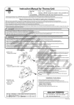
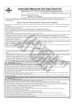
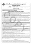
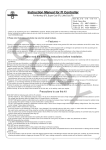
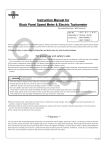
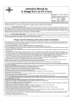
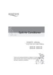
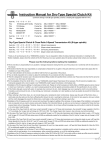
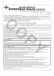
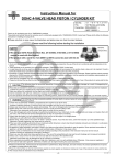
Aluminium Clutch Cover Kit Instruction Manual
CO
Item No.:02−01−5042
Applied to
Ape50
Frame No.
AC16-1000001∼
AC16-1600001∼
Ape50 (FI)
Ape50 (FI Type D) AC18-1000001∼
HC07-1000001∼
Ape100
Ape100 Type D HC13-1000001∼
AD14-1000001∼
XR50 Motard
HD13-1000001∼
XR100 Motard
Thank you for purchasing one of our products. Please strictly follow the instructions to install and use the products. Before fitting the products, please
be sure to check the contents of the kit. If you have any questions about the products, please kindly contact your local TAKEGAWA dealer.
PY
◎ Please note: Illustrations and photos may vary from the actual hardware.
Please read following instructions before installation.
◎ We do not take any responsibility for any accident or damage whatsoever arising from the use of the products not in conformity with the instructions
in the manual.
◎ We shall be held free from any kind of warranty whatsoever of products other than this product if the glitch takes place on the other products than
this one after the installation and use of this product.
◎ This product is designed for exclusive use with the above-mentioned type of motorcycle and frame numbers only. Please take note that this product
cannot be mounted on other types of motorcycles.
◎ We do not have any information or service data on the combination of our products and other manufacturers’ products.
◎ Please be informed that, mainly because of improvement in performance, design changes, and cost increase, the product specifications and prices
are subject to change without prior notice.
◎ This manual should be retained for future reference.
CAUTION
The following show the envisioned possibility of injuries to human bodies and property damage as a result of disregarding the
following cautions.
・Work on motorcycles only when the engine and the exhaust system are cool to avoid burns.
・Prepare appropriate tools and work properly to avoid the breakage of parts or injuries.
・Always use a torque wrench to tighten bolts and nuts securely to the specified torque to avoid these parts getting damaged or loose.
・As some products and frames have sharp edges or protruding portions, work with your hands protected to avoid injuries.
・Before riding, always check such parts as screws for loose.
If you find loose ones, screw them securely up to the specified torque to avoid parts coming off.
WARNING
The following show the envisioned possibility of human death or serious injuries to human bodies as a result of disregarding the
following cautions.
・Always drive the engine in a well-ventilated place, and do not switch the engine on in an airtight place.
(Otherwise, you will suffer from carbon monoxide poisoning. )
・When you notice something abnormal with your motorcycle, stop riding immediately and park your motorcycle in a safe place to avoid an accident.
・Before working, place the motorcycle on the level ground to stabilize its position for safety to avoid the motorcycle overturning.
・Check or perform maintenance of parts correctly according to the procedures in the instruction manual or a service manual.
(Improper checking or maintenance could lead to an accident.)
・If you find damaged parts when checking and performing maintenance, do not use these parts any longer, and replace them with new ones. (The continued use of these damaged parts as they are could lead to an accident.)
・As gasoline is highly flammable, never place it close to fire. Make sure that nothing flammable is near the gasoline. Since vaporized accumulation of gasoline
is at the high risk of explosion, work in a well-ventilated place.
-1-
Aug./22/’
12
Kit Contents
27
25
19
CO
20
7
8
1
18B
18A
9
28
17
16
22
23
23
23
24
23
23 23
No.
1
2
3
4
5
6
7
8
9
10
11
12
13
14
15
16
17
18A
18B
19
20
21
22
23
24
25
26
27
28
11
12
15
13
21
10
10
9
26
2
3
4
5
6
PY
23
14
22
23
6
23
23
Parts Names
Right-side crankcase cover assembly
Oil filter spring
Oil filter element
O-ring 40MM
Oil filter cover
Flange bolt 6X16
Hole cap
O-ring 30MM
Sealing washer 10MM
Oil plug bolt
O-ring 15MM
Thermostat hole cap
Oil seal 18X29X7
Oil pot window set
Oil seal 12X18X5
Clutch lever spring
Clutch lever COMP.
Clutch lifter pin (For 5-speed transmission)
Clutch lifter pin (For 6-speed transmission)
Right-side crankcase cover gasket
Clutch cable receiver
Flange bolt 6X35
Flange bolt 6X40
Flange bolt 6X80
Flange bolt 6X100
Rubber separator
Clutch cable COMP.
Clutch cable adapter
Shim ring 12X18X0.3
Qty
1
1
1
1
1
2
1
1
2
2
1
1
1
1
1
1
1
1
1
1
1
1
1
6
1
1
1
1
4
Repair Parts Item No.
11300-GEY-T10
15413-181-T00
00-02-0027
00-02-0040
15412-GEF-T10
00-00-0174
00-07-0074
00-01-0034
00-07-0010
90145-GEY-T00
00-00-0186
15411-GEF-T00
00-02-0217
00-02-0031
00-02-0093
22815-GEY-T00
22810-GEY-T02
22366-ARC-T10
22366-GCR-T10
00-01-0097
50135-GN1-T00
00-00-0180
00-00-0178
00-00-0338
00-00-0339
00-02-0114
22870-GEY-T10
22872-GEY-T00
00-02-0216
24
21
23
23
In packs of
1
1
1
1
1
6
1
4
10
1
4
1
1
1
1
1
1
1
1
1
1
4
4
3
3
1
1
1
1
※ Please order repair parts with the Repair Part Item No. Without the repair part item No., we may not be able to provide the correct parts.
Some parts are only available as a set. Please order them with the set number.
-2-
Aug./22/’
12
Features
○ We have equipped the clutch cover with an oil filter using a paper-type element.
○ A thermostat with a spring, made of a shape-memory alloy, is available for use in this kit as an optional extra. (Patent granted.)
○ The clutch cover and oil filter cover are made of die-cast aluminum.
○ The surface is barrel-polished.
○ This kit enables the flow of oil from the clutch cover to oil cooler.
○ This kit comes with an oil pot window with a high level of durability, which is highly evaluated by the Monkey model riders.
○ Equipped with a large-size oil filler cap.
○ Lifter pin direct system, which dose not utilize the cam and adjusting lever, is employed as a clutch operation system.
CO
Precautions for use
● An oil cooler unit, which is installable to the oil filter cover, cannot be installed to this kit due to the size difference. Oil lines can
be used only at the specified location.
● A conventional oil cooler hose cannot be installed to this kit due to the size difference. Please use the special one for exclusive with the die-cast cover.
● If you are using an oil cooler kit to which an oil hose is connected from the cylinder, NEVER install a thermo unit or oil hole plug. There is a possibility that the engine will be damaged due to the oil passage blockage.
● Please refer to a relative instruction manual for a thermo unit, an oil cooler, and so on.
● Please do the work, referring to a HONDA’s service manual for Ape50, Ape100, XR50 Motard and XR100 Motard.
PY
∼ About Oil Lines ∼
о In the case of Ape50 and XR50 Motard, all the engine oil is provided to the cylinder head and the crankshaft via oil filter.
оAn oil line in the crankcase of Ape100, Ape100 Type D and XR100 Motard differs in shape from the one in Ape50 and XR50 Motard. However, by attaching
the provided rubber separator onto the first three types of motorcycles, all the engine oil can be arranged to flow through the oil filter to the cylinder head
and crankshaft just like the latter two types of motorcycles.
Oil Line Diagram
To cylinder head
To cylinder head
Oil filter
Flow of engine oil
To cylinder head
Oil filter
Rubber separator
(supplied in the Kit)
Oil
pump
Oil
pump
Oil
pump
To crank shaft
Crankcase
Right crankcase cover
In the case of Ape50 and XR50 Motard
To crank shaft
Crankcase
Right crankcase cover
In the case of Ape100,Ape100 TypeD,
and XR100 Motard
-3-
To crank shaft
Crankcase
Right crankcase cover
In the case of stock Ape50 / 100,
and stock XR50 / 100 Motard
Aug./22/’
12
Installation Procedures
1. Stabilize the vehicle with a maintenance stand.
2. Prepare a tray. Remove the drain bolt and drain engine oil.
8. Install the clutch lever spring and
the clutch lever to the cover.
※Apply engine oil to the clutch lever
shaft.
Right-side step
3. Unfasten the bolt on the kick starter
arm, and remove the starter.
Unfasten two bolts on the right-side
step bracket, and detach the Rear brake pedal
CO
bracket, rear brake pedal, sleeve
and spring.
Return spring, sleeve
4. Disconnect the clutch cable.
Detach the engine-mounting upper
nuts, and pull out the mounting bolts
to demount the clutch cable
receiver.
Fix the clutch cable receiver
included in the kit, and fasten the
engine mounting nuts to the
specified torque.
(Installation of rubber separator)
In the case of Ape100, Ape100 Type D or XR100 Motard
As shown in the photo, attach the rubber separator onto the oil line groove
on the right side crankcase with the TAKEGAWA logo being visible and its
protrusion being right in the dent of the case.
※ Install the rubber separator without using a hammer or the like.
※ First attach the clutch cover gaskets to the crankcase.
And check that the arrowed hole is not blocked up by the rubber
separator. And lastly attach the clutch cover.
Adjust nut
Cable receiver
Caution: Apply the specified torque.
Install the rubber
separator with
the TAKEGAWA
logo being
visible.
Torque: 44 N・m (4.5 kgf・m)
6. Remove two dowel pins and a
gasket.
Dowel pins
PY
Bolt
Make sure that this
hole is not blocked up.
Install the
separator with
its protrusion
being right in the
dent of the case.
Gasket
7. Remove the clutch lifter pin.
Put 3 pcs of shim rings through the supplied lifter pin, and install them on the bearings of clutch lifter plate.
Bearing
Shim ring
Clutch lever
9. Detach the oil filter screen and clean it. Then, fix it firmly to the grooves in
the crankcase.
Bolts
Lock nut
5. Unfasten the bolts on the right-hand
crankcase cover and remove the
right-side cover.
Clutch lever spring
10. Clean up case’s mating surfaces, attach the dowel pins and a new gasket, and install the cover.
※Be careful not to give damages to the crank shaft and oil seals on the kick
starter spindle
11. Fasten temporarily the cover with the supplied bolts, and check the free
play of the clutch lever. The correct free play is between about 6 ∼ 15 degrees (about 5 ∼ 10 mm)
※You can adjust it by changing the number of shim rings attached on the lifter pin.
If the free play is less, decrease shim rings.
If it is more, increase shim rings.
When you have the appropriate free play, tighten them to the specified torque in a crisscross pattern in two or more steps.
Caution: Apply the specified torque.
Torque: 10 N・m (1.0 kgf・m)
※ Two kinds of clutch lifter pins are available to suit the kinds of
transmissions. Be sure to use a 5-speed transmission lifter pin for a
5-speed transmission and a 6-speed transmission lifter pin for a
6-speed transmission.
For 5-speed transmission
For 6-speed transmission
One line
6
41.3 mm
40 mm
-4-
∼
15
°
ab
ou
t5
∼
10
m
m
Aug./22/’
12
12. Place the oil filter spring on the protrusion of the right-side crankcase cover oil filter.
Install an oil filter element with the rubber seal facing to the outer side.
Apply engine oil to the O-rings of the oil filter cover, and install them to the
right-side crankcase cover, being careful that the O-rings are in the right
position. And fix and tighten the flange bolt to the specified torque.
CO
Important Notice
Oil Cooler Installation
● In case a thermo unit is to be installed:
1. Install a thermo unit.
Caution: Apply the specified torque.
Torque: 9 N・m (0.9 kgf・m)
13. Connect the clutch cable, and adjust the free play on it.
Free play on the clutch: 10-20 mm at the end of the clutch lever.
For stock lever, install the clutch cable COMP. while putting it through the
clutch cable adapter.
※This procedure is not required when you use TAKEGAWA Clutch Lever 2. Unfasten two oil plug bolts, and install an adapter suitable for the kind of hose you will use. Then connect the hose.
※ Please see the instruction manual for the thermo unit.
※Please see the instruction manuals for the oil cooler kit and the adapter.
ASSY.
14. Apply grease to the sleeve, which
please fix to the brake pedal, and
Rear brake pedal
tighten loosely the spring and
sleeve
right-side step bracket with bolts. Bolts
Apply the rear brake, and after brake-related sections get warmed up, fasten the bolts to the specified torque.
PY
Rubber hose
Return spring
● In Case of Oil Hose Installation on the Cylinder Head Side
CAUTION:NEVER install a thermo unit or
an oil hole plug if you do not connect an oil hose to the clutch cover.
right-side step
Caution: Apply the specified torque.
Torque: 39 N・m (4.0 kgf・m)
There is a possibility that the
engine is damaged due to the
oil passage blockage.
15. Fix the kick starter arm, and screw up the bolt(s) to the specified torque.
Caution: Apply the specified torque.
Torque: 26 N・m (2.7 kgf・m)
16. Tighten the drain bolt to the specified torque, and pour 1,000cc of engine
oil.
Caution: Apply the specified torque.
Torque: 25 N・m (2.5 kgf・m)
※Make sure that there is no oil leakage.
In case an oil cooler is not installed:
NEVER install a thermo unit or an oil hole plug. And in case the thermo unit and/or an oil hole plug is installed, DO be sure to remove
it or them.
CAUTION:There is a possibility that the
engine is damaged because Appropriate engine oil level seen through the oil pot,
just for your guidance
the oil passage will be blocked
At oil change: 0.9 liters
1.0 L
0.9 L
0.8 L
Allegri’s hose
when the thermo unit or an oil
hole plug is installed.
At oil filter change: 1.0 liters
At overhaul: 1.1 liters
Co.,Ltd.
3-5-16 Nishikiorihigashi Tondabayashi Osaka Japan
TEL : 81-721-25-1357 FAX : 81-721-24-5059
URL : http://www.takegawa.co.jp
-5-
Aug./22/’
12