1
Power supply terminals: L, N
Input rated voltage: 230 V AC
Input voltage tolerance: from -15 to +10 %
Supply voltage control indicator: LED green
MOD
A
External release terminals: IN, IN (released from L or N)
DIMENSIONS
Release current: 510 μA
ED E F G
C
Time measure accuracy: 0,2%
U
B
U
t1 t2
t1
H
ON
t1 t2
ED E F G
C
B
A
H
ON
C
t1
DE
C
F
B
A
G
H
ON
t2
ED E F G
H
ON
D
U
U
U
PERMANENT SWITCH ON MODE - After the supply voltage
has been applied the relay is switched on permanently. When
choosing the mode t1 and t2 time adjustment does not matter.
OFF
ED E F G
H
ON
PERMANENT SWITCH OFF MODE - After the supply voltage
has been applied the relay is switched off permanently. When
choosing the mode t1 and t2 time adjustment does not matter.
OFF
External signal release:
SWITCH ON/OFF DELAY - (retriggerable) after the impulse release has been applied to the powered system (growing value)
let the relay be switched off (pos.11-12), the same, starts the
preset time t1 measurement. After the time is over the relay
is switched on (pos. 11-14). After the impulse release fade is
detected (falling modulated voltage), the system starts preset t2
time measurement and after it is finished the relay is switched
off (pos.11-12). In case impulse duration is longer than the preset time t1 the relay is not switched on. Applying the impulse
release during the preset t2 time measurement does not cause
switching off the relay but it starts time measurement after the
impulse fade) (falling modulated voltage).
Time adjustment range t2: 0,1 s to ∞ (step+smooth)
Power/relay supply indicator and time measure: from LED red
Output relay parameters: 1NO/NC-16 A/250 V AC1 4000 VA
• 10 operating modes (external release
or from power supply voltage),
• supply voltage control signal - LED green,
• power/relay supply indicator and time
measure - LED red,
• two time ranges adjustment,
• wide time adjustment range,
• time measure accuracy,
• constant switch on, switch off function,
• voltage relay output - 1 change over
contact (NO/NC) contact max 16 A
capacity,
• doublemodular casing.
MOD
Number of terminal clamps: 8
ED
EF
C
B
A
Section of connecting cables: from 0,2 to 2,50 mm2
Ambient temperature range: from -20 to +45 oC
G
H
ON
E
S
t1
t2
t1
OFF
Operating position: freely
Mounting: rail TH 35 (PN-EN 60715)
Protection degree: IP20 (PN-EN 60529)
SWITCH ON/OFF DELAY - (non-retriggerable) - after the impulse release has been applied to the powered system (growing
value) let the relay be switched off (pos.11-12) starts the preset
time t1 measurement. After the time is over the relay is switched on (pos. 11-14). After the impulse release fade is detected (falling modulated voltage), the system starts preset t2 time
measurement and after it is finished the relay is switched off
(pos.11-12). Release input state can change during the time t2
measurement and does not affect on functioning of the system.
In case impulse duration is shorter than the preset time t1 the
relay is not switched on.
Protection level: II
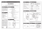
CONNECTING
Overvoltage category: II
Dimensions: double-modular (35 mm) 90x35x66 mm
Weight: 0,11 kg
Reference standards: PN-EN 60730-1; PN-EN 60730-2-7
PN-EN 61000-4-2,3,4,5,6,11
MOD
Pollution degree: 2
ED E
C
B
A
FG
H
ON
F
S
t1
t2
t1
OFF
Power supply terminal (L)
Release terminals
(IN, IN)
MOD
APPEARANCE
ED E F
C
B
A
MOD
Power supply terminal (N)
Supply voltage
control indicator
Relay supply indicator
G
H
ON
G
IMPULSE GENERATION WITH AN ALTERNATE TIME DURATION - powered system switches on the relay after impulse
release (growing value) switches on the relay for t1 time, and it
switches off. The next impulse release causes the relay switches
on for t2 time. Another one switches on the relay for t1 time, etc,
The impulse release time duration does not influence switches
on relay time.
S
t1
t2
t1
OFF
ED E F G
C
B
A
H
ON
H
S
t
t1 t2
t
t1
OFF
Operating mode choice
Time adjustment choice t1
Relays output (supply) terminals
(14, 11, 11, 12)
ED E F G
C
B
A
H
ON
OFF
or
MOD
Smooth time adjustment t2
SWITCH OFF DELAY RELEASED BY FALLING MODULATED
VOLTAGE - powered system switches on the relay after impulse
release switches on the relay. Impulse release fade causes adjusted t1 time measurement starts with the relay switch off for
t2 time. During t2 time the system is resistant to signals release.
After the t2 time is finished the relay is switched on again in the
moment of applying impulse release (growing value).
Simulation modes:
Smooth time adjustment t1
MOD
The device is designed for
single-phase installation and
must be installed in accordance with standards valid
in a particular country. The
device should be connected
CAUTION according to the details included in this operating manual. Installation,
connection and control should be carried
out by a qualified electrician staff, who act in
accordance with the service manual and the
device functions. Disassembling of the device is equal with a loss of guarantee and can
cause electric shock. Before installation make
sure the connection cables are not under voltage. The cruciform head screwdriver 3,5 mm
should be used to instal the device. Improper
transport, storage, and use of the device influence its wrong functioning.
It is not advisable to instal the device in the
following cases: if any device part is missing
or the device is damaged or deformed. In case
of improper functioning of the device contact
the producer.
FLASHER STARTING WITH ON - (Starting from the switch on
position). After the supply voltage [U] has been applied, the
relay is switched on immediately (pos.11-14) for time. After the
time is over, the relay switches off (pos.11-12) for t2 time and its
another switch on mode for t1 time. The next switch on interval
appears after power supply voltage reset.
t1 t2 t1 t2 t1 t2
Time adjustment range t1: from 0,1 s to 100 days (step+smooth)
FEATURES
FLASHER STARTING WITH OFF - (Starting from the switch
off position). After the supply voltage [U] has been applied,
the preset time t1 is measured. After the time is over, the relay
switches on (pos.11-14) for t2 time and it switches off again for
t1 time (pos.11-12). The next switch on interval appears after
power supply voltage reset.
t1 t2 t1 t2 t1 t2
OFF
C
B
A
SWITCH OFF DELAY - after the supply voltage [U] has been
applied, the output relay [R] switches on immediately (pos.1114), and the preset time t1 is measured. After the preset time is
measured, the relay [R] is switched off (pos.11-12) for t2 time
and its another switch on mode. The next switch on interval
appears after power supply voltage reset.
U
OFF
E
SWITCH ON DELAY - after the supply voltage [U] has been
applied the t1 time measure starts. After the time is over the
relay switches on (pos. 11-14) for t2 time. The next switch on
interval appears after power supply voltage reset
t2
OFF
C
B
A
Operating modes number: 10
A
OFF
BA
MOD
Nominal frequency: 50 / 60 Hz
Rated power consumption: 35 mA
H
ON
C
B
ON
4097605
The multifunctional time relay
4097605 has a time function in automation and control systems. It is equipped
with 10 independent operating modes
released by power supply voltage or external impulse command (coming from L or
N line). It has a wide two time adjustment
range t1 and t2 and constant switch on/
off function. The mode change is possible
without waiting for the current cycle to be
finished.
ED E F G
OFF
TECHNICAL DATA
Power supply voltage release:
MOD
DESCRIPTION
1.Disconnect the power supply from the
mains by the phase fuse, the circuit-breaker or the switchdisconnector that
are joined to the proper circuit.
2.Check if there is no voltage on connection cables by means of a special
measure equipment.
3.Install 4097605 device in the switchboard on TH 35 DIN rail.
4.Connect the cables with the terminals
according to installing diagram.
5.Switch on the power supply from the
mains.
6.Choose the required operating mode by
Mode knob.
7.Adjust the time t1 and t 2 using the TIMEx, RANGEx knob where t x=TIMExRANGEx.
x
FUNCTIONING
MOD
Malmbergs Elektriska AB, PO Box 144, SE-692 23 Kumla, SWEDEN
Phone: +46 (0)19 58 77 00 Fax: +46 19 57 11 77 [email protected] www.malmbergs.com
MOUNTING
MOD
INSTRUCTION MANUAL
MOD
TIME RELAY 4097605
DE
E
C
B
A
F
G
H
ON
OFF
Time adjustment choice t2
In order to cause simulation mode one of the release terminals
(IN) with L or N line must be externally connected. Simulation
mode can operate in MODE=C or MODE=D cycle. Time courses analogical to C and D mode. RANGE must be adjusted for
every t1 and t2 time whereas TIME is changed accidentally by
the system.
U
Diode signal description
☼
Relay switched off,
time measure off
☼
Relay switched on
time measure off
☼
☼
☼
U
Diode signal description
☼
Relay switched off,
time measure on
☼
Relay switched on,
time measure on