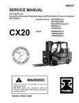
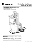
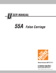
1
F-code
Section
C-code
M
Introduction, Service Manual
Version no
T-code
001
395/396/397/398/399
Introduction, Service Manual
The information in this Service Manual covers models
FR18S/23S-2A and FR15DR-2A.
Federal and State laws require that operators be completely
trained in the safe operation of trucks in accordance with
OSHA regulation 1910.178.
An Operator’s Manual is sent with every Komatsu forklift
truck when it is manufactured. If the Operator’s Manual is
missing from the truck, a new manual may be obtained by
contacting:
Komatsu Forklift U.S.A., Inc.
14481 Lochridge Blvd., Bldg. 2
Covington, Georgia 300014
(770) 788-3612
This Service Manual is not a training manual. The information
contained in this service manual is intended as a guide to
help trained, qualified, and authorized technicians safely
service the truck.
The Service Manual is divided into four separate sections,
which cover needed information for servicing the truck types.
The main subject for each of the sections are as described
below.
SECTION
© Komatsu Forklift U.S.A., Inc.
SUBJECT
M
MACHINE INFORMATION
P
PLANNED MAINTENANCE
S
SERVICE INSTRUCTIONS
O
OPTIONS
Master Service Manual
2000-08-04
29
F-code
Section
C-code
M
Contents, Section M
Version no
T-code
001
Contents, Section M
1. Machine Information
© Komatsu Forklift U.S.A., Inc.
M1.0
GENERAL PRODUCT INFORMATION
M2.0
TECHNICAL SERVICE DATA
M3.0
ORDERING SPARE PARTS
Master Service Manual
2000-08-04
31
F-code
Section
C-code
M1.0
General Product Information
Version no
001
T-code
395/396/397/398/399
General Product Information
1. Presentation of the Rider Trucks.
The FR18S/23S-2A are battery powered reach trucks. The
FR15DR-2A is a battery powered deep reach truck.
These trucks are intended solely to be operated handling
pallets or similar load carriers indoors. The trucks are
equipped with a steering wheel with all the controls for
operating within easy access.
The trucks have various maximum lifting capacities (review
data plate on the truck to note the maximum lifting capacity)
and are equipped with a 24V or 36V electrical system. Speed
of the truck is regulated by means of a transistor controller to
provide infinite control of acceleration and speed while
driving.
The forks and auxiliary functions are controlled by means of a
transistor controller. Control of the lift and auxiliary functions
are done electrically with the levers on the control pod.
Control of the speed and positioning of the forks when
stacking is done by the position of the levers.
The trucks can be fitted with different accessories including
sideshifter, warning light, lights/fan package, travel alarm,
and adjustable driving lights. The trucks can be specially
equipped to work in cold conditions.
1.1. Truck Side Views
The terms rearward and forward used indicate the front and
back side of the truck as viewed from the operator’s line of
sight for proper operation of truck. The terms right-hand and
left-hand used indicate the right and left side of the truck as
viewed from the operator’s line of sight for proper operation of
truck.
© Komatsu Forklift U.S.A., Inc.
Master Service Manual
2000-08-04
33
F-code
Section
C-code
M1.0
General Product Information
Version no
T-code
001
395/396/397/398/399
1.2. Open Back Compartment
The truck compartment has an open back design. The United
States Department of Labor Occupational Safety and Health
Administration (OSHA) has determined that when a stand up
narrow aisle lift truck tips over the operator should be trained
to step off the truck. The open back design allows the
operator to make the quickest exit from the truck should the
truck begin to tip over or fall from an elevated height such as
a loading dock or ramp. The ease of entering and exiting the
open back design also minimizes operator fatigue.
1.3. Intended Truck Application
The trucks are solely designed and manufactured to handle
goods. The trucks should be fitted with the appropriate
accessories relevant to the application.
34
Master Service Manual
2000-08-04
F-code
Section
C-code
M1.0
General Product Information
Version no
001
T-code
395/396/397/398/399
1.4. Prohibited Truck Application
The trucks are designed for handling goods indoors. It is not
permitted to use the trucks for other purposes including the
following:
l
As a towing tractor for trailers.
l
To tow other trucks.
l
To transport/lift passengers.
l
To drive on gravel or grass.
1.5. Truck Data
The following table provides information regarding some
technical data which is of value with daily use of the trucks.
The lifting capacity, lifting height, and weight of the truck can
be found on the truck data plate.
© Komatsu Forklift U.S.A., Inc.
Master Service Manual
2000-08-04
35
F-code
Section
C-code
M1.0
General Product Information
Version no
T-code
001
395/396/397/398/399
1.6. FR18S-2A Dimensions
The following diagram shows external dimensions for the
FR18S-2A truck in its standard design.
10% Gradient Performance-Loaded
36
Master Service Manual
2000-08-04
F-code
Section
C-code
M1.0
General Product Information
Version no
001
T-code
395/396/397/398/399
1.7. FR23S-2A Dimensions
The following diagram shows external dimensions for the
FR23S-2A truck in its standard design.
10% Gradient Performance-Loaded
© Komatsu Forklift U.S.A., Inc.
Master Service Manual
2000-08-04
37
F-code
Section
C-code
M1.0
General Product Information
Version no
T-code
001
395/396/397/398/399
1.8. FR15DR-2A Dimensions
The following diagram shows external dimensions for the
FR15DR-2A truck in its standard design.
10% Gradient Performance-Loaded
38
Master Service Manual
2000-08-04
F-code
Section
C-code
M1.0
General Product Information
Version no
001
T-code
395/396/397/398/399
1.11. Data Plate
The illustration below shows the data plate used on the truck.
Legend
1
2
3
4
5
6
7
8
9
10
11
12
13
© Komatsu Forklift U.S.A., Inc.
Truck model number
Truck serial number
Weight less battery
Maximum battery weight
Minimum battery weight
Truck voltage DC
Battery type UL class
Battery maximum AMP hours
Truck type
Mast serial number
Attachment
Maximum degree rear tilt
Truck capacity
Master Service Manual
2000-08-04
41
F-code
Section
C-code
M1.0
General Product Information
Version no
T-code
001
395/396/397/398/399
2. Main Components
1 Hydraulic valve:
The valves are located to provide easy access.
2 Battery:
24/36V with different capacities and weights.
3 Battery connector:
The truck is connected to the battery through the battery
connector. When charging the battery, do not connect the
battery charger to the battery connector at the truck
chassis.
4 Hydraulic unit:
Pump motor and hydraulic pump are an integrated unit.
5 Drive unit with brake:
Drive motor, gears, drive wheel and electrical brake
combined in the drive unit.
6 Electrical steering:
A servo steer motor drives a gear ring, enabling the drive
unit to be rotated through 360 degrees in either direction.
7 Data plate:
See “Data Plate” on page 41.
8 Cover:
Removable to provide access for servicing.
9 Pedal:
Brake pedal.
10 Control console:
The control console can be adjusted to a suitable height
and angle to obtain a comfortable working position. The
steering, hydraulic functions, horn, parking brake, preset
height, travel direction, key switch, and any extra
hydraulic functions are all controlled from this console.
The position of the console may be set in 1 of 3 positions;
forward facing, 45 degrees, or side stance.
11 Instrument panel:
This provides information on the truck’s running hours,
time display, error codes, travel direction, parking brake,
steering angle and battery status.
12 Mast:
The mast is a clear view model.
42
Master Service Manual
2000-08-04
F-code
Section
C-code
M1.0
General Product Information
Version no
001
T-code
395/396/397/398/399
13 Electronics:
The electronics are in a protected compartment.
14 Control circuit fuse: (for fuse size and part number see
page 59)
15 Steering circuit fuse: (for fuse size and part number see
page 59)
16 Drive motor fuse: (for fuse size and part number see
page 59)
17 Pump motor fuse: (for fuse size and part number see
page 59)
18 Right foot pedal
An operator must keep all of his or her body in the
operator’s compartment at all times. The area of the
operator’s compartment in the truck is designed so that an
operator can do so. A red triangle (reminder light) will be
displayed on the instrument panel if the right foot pedal is
not depressed. This feature reinforces that the operator
must take advantage of the area of the operator ’s
compartment and keep all of his or her body in the
compartment.
19 Emergency stop
The emergency stop switch will stop all control and power
functions.
© Komatsu Forklift U.S.A., Inc.
Master Service Manual
2000-08-04
43
F-code
Section
C-code
M1.0
General Product Information
Version no
T-code
001
395/396/397/398/399
Main Components of Truck
44
Master Service Manual
2000-08-04
F-code
Section
C-code
M1.1
Inch (SAE) and Metric Fasteners
Version no
T-code
002
Inch (SAE) and Metric Fasteners
1. Introduction
Threaded fasteners such as bolts, nuts, cap screws, and
studs are made to specifications that describe the mechanical
strength and hardness of the fastener. A fastener used in a
design application is selected in accordance with its
specifications. Parts used on this truck are purchased from
many countries. Many of these fasteners are similar but
cannot be used as direct replacements.
Service persons must use replacement fasteners that have
the same specifications. Fasteners made to each
specification have identification marks for that specification.
This specification is commonly called “grade” for SAE
standards and “property” for metric standards. This section
describes the identification of some common fasteners.
The metric system used is described as Sl (International
System of Units, also called SI in all languages). The SI
system of measurement is described in ISO Standard 1000,
1973.
© Komatsu Forklift U.S.A., Inc.
Master Service Manual
2002-01-16
45
F-code
Section
C-code
M1.1
Inch (SAE) and Metric Fasteners
Version no
T-code
002
2. Nomenclature, Threads
The thread design is specified by a series of numbers and
letters for inch and metric fasteners (see figure below). The
diameter of the shank of the fastener is shown first in the
series, e.g. M12=12 mm, M20=20 mm (1/2=1/2 inch, 3/4=3/4
inch).
1
/2 x 13 UNC - THREAD
(DIA. x NO. OF THREADS PER INCH)
M12 x 1.75 mm - THREAD
(mm DIA. x THREAD PITCH mm)
The number of threads per inch is normally not shown for inch
nomenclature and only the UNC (Unified National Coarse) or
UNF (Unified National Fine) is shown. This number of threads
per inch is not shown because a UNC or UNF fastener has a
standard number of threads per inch for a specific diameter.
The length of a shank is often indicated as part of the
description of a fastener. This length is shown in inches for
inch fasteners and in millimeters for metric fasteners.
A cap screw will have the following description:
46
Master Service Manual
2002-01-16
F-code
Section
C-code
M1.1
Inch (SAE) and Metric Fasteners
Version no
T-code
002
3. Strength Identification
The most common property classes for metric fasteners are
8.8 and 10.9. The property class is marked with a number on
the head of the cap screw or on a nut. Property classes less
then 8,8 are often not marked. Grades for inch bolts go from 2
to 8. Grade 2 fasteners normally do not have marks. The
following tables show the marks that identify the grades and
property classes for different fasteners.
! WARNING
NOTE!
© Komatsu Forklift U.S.A., Inc.
Master Service Manual
When fasteners must be replaced the new
fasteners must be of the same strength or
greater than the original fasteners. The new
fasteners must also be the correct size.
Identification marks are according to bolt
strength. The higher the number, or the
increase in the number of marks, indicates
increased bolt strength.
2002-01-16
47
F-code
Section
C-code
M1.1
Inch (SAE) and Metric Fasteners
Version no
T-code
002
Table 1. Bolt and Screw Designations
48
Master Service Manual
2002-01-16
F-code
Section
C-code
M1.1
Inch (SAE) and Metric Fasteners
Version no
T-code
002
Table 2. Stud and Nut Designations
© Komatsu Forklift U.S.A., Inc.
Master Service Manual
2002-01-16
49
F-code
Section
C-code
M1.1
Inch (SAE) and Metric Fasteners
Version no
T-code
002
Table 3. Torque Nut Designations
50
Master Service Manual
2002-01-16
F-code
Section
C-code
M1.1
Inch (SAE) and Metric Fasteners
Version no
T-code
002
Table 4. Torque Nut with Nylon Insert Designations
© Komatsu Forklift U.S.A., Inc.
Master Service Manual
2002-01-16
51
F-code
Section
C-code
M1.1
Inch (SAE) and Metric Fasteners
Version no
T-code
002
Table 5. Fastener Torque Values
*
Property class 8.8, Protective Treatment CMHC
Specification “H” (zinc phosphate), applies also to
internally threaded fasteners made of property
class 8 material.
** Property class 10.9, Protective Treatment CMHC
Specification “H” (zinc phosphate), applies also to
internally threaded fasteners made of property
class 10 material.
*** Property class 12.9, Protective Treatment CMHC
Specification “H” (zinc phosphate), applies also to
internally threaded fasteners of property class 12
material.
52
Master Service Manual
2002-01-16
F-code
Section
C-code
M1.1
Inch (SAE) and Metric Fasteners
Version no
T-code
002
© Komatsu Forklift U.S.A., Inc.
Master Service Manual
2002-01-16
53
F-code
Section
C-code
M1.1
Inch (SAE) and Metric Fasteners
Version no
T-code
002
54
Master Service Manual
2002-01-16
F-code
Section
C-code
M1.1
Inch (SAE) and Metric Fasteners
Version no
T-code
002
4. Conversion of Metric and English
Units
© Komatsu Forklift U.S.A., Inc.
Master Service Manual
2002-01-16
55
F-code
Section
C-code
M1.1
Inch (SAE) and Metric Fasteners
Version no
T-code
002
56
Master Service Manual
2002-01-16