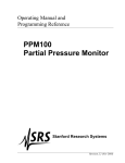
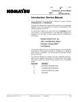
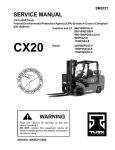
1
© 2002 Kalmar AC, Inc., Covington, Georgia
All Rights Reserved.
F-code
Section
C-code
Standard Codes
Version no
T-code
000
Standard Codes
B-Code
= Business area
F-Code
= Product family
T-Code
= Product type
C-Code
= Component function
Worksheet standard
W-Code = Working code
R-Code
= Reason code
SO-Code = Assortment
F-Code List
PS - Powered Pallet Stacker
T-Code List
Code
Model
395
NR35B
396
NR45B
397
ND30B
398
NS40B
399
NS50B
C-Code List
No Function Group
© Kalmar AC, Inc.
C-Code
0
Chassis
0000
1
Motors
1000
2
Drive Gear / Transmission
2000
3
Brake / Wheel System
3000
4
Steering System
4000
5
Electrical System
5000
Master Service Manual
2000-08-04
1
F-code
Section
C-code
Standard Codes
Version no
T-code
000
2
6
Hydraulic / Pneumatic System
6000
7
Operating Function-lifting Mast / Cylinders
7000
8
Peripheral / Installation Equipment
8000
9
Options / Attachments
9000
Master Service Manual
2000-08-04
Table of Contents
Table of Contents
Standard Codes ............................................................................................. 1
Warning Symbols ......................................................................................... 15
Warning Levels ......................................................................................... 15
Prohibitory Symbols .................................................................................... 16
Ordinance Symbols .................................................................................. 16
Safety ............................................................................................................ 17
General Safety .......................................................................................... 17
Battery Safety ............................................................................................... 21
Static Safety .................................................................................................. 26
Welding Safety ............................................................................................. 27
Introduction, Service Manual ...................................................................... 29
Contents, Section M ..................................................................................... 31
Machine Information ................................................................................. 31
General Product Information ...................................................................... 33
Presentation of the Rider Trucks. ............................................................. 33
Main Components ..................................................................................... 42
Inch (SAE) and Metric Fasteners ...............................................................
Introduction ...............................................................................................
Nomenclature, Threads ............................................................................
Strength Identification ...............................................................................
Conversion of Metric and English Units ....................................................
45
45
46
47
55
Technical Service Data ................................................................................ 57
Ordering Spare Parts ................................................................................... 61
Contents, Section P ..................................................................................... 63
Planned Maintenance ............................................................................... 63
Introduction, Maintenance .......................................................................... 65
Jacking Truck Off The Floor ..................................................................... 66
Lubricants ................................................................................................. 68
Service Schedule ......................................................................................... 71
Planned Maintenance Schedule ............................................................... 71
© Kalmar AC, Inc.
Master Service Manual
2001-10-12
3
Table of Contents
Planned Maintenance Procedures ............................................................ 76
Lubrication Chart ......................................................................................... 83
Oil and Grease Specifications ....................................................................
Approved Oils and Grease .......................................................................
Grease Location Points ............................................................................
Mast Adjustment Points ............................................................................
84
84
85
86
Contents, Section S ..................................................................................... 87
Service Instructions .................................................................................. 87
Troubleshooting Guidelines .......................................................................
General .....................................................................................................
Electrical ...................................................................................................
Hydraulic ...................................................................................................
Definitions .................................................................................................
89
89
91
96
97
Chassis ......................................................................................................... 99
General ..................................................................................................... 99
Dash ........................................................................................................ 100
Motor Compartment Door ........................................................................ 101
Left-Hand Side Panel ............................................................................... 102
Operator Compartment Panel .................................................................. 103
Main Card Access Panel ......................................................................... 103
Battery Compartment ................................................................................. 105
Battery Retainer Plates ............................................................................ 106
Battery Rollers ......................................................................................... 106
Driver Controls ............................................................................................ 107
Brake Pedal, NS40B/NR35B ........................................................................
Pedal Removal ........................................................................................
Pedal Bearing Replacement ....................................................................
Pedal Adjustment .....................................................................................
109
110
111
111
Brake Pedal, NS50B/NR45B/ND30B ..........................................................
Pedal Removal ........................................................................................
Pedal Bearing Replacement ....................................................................
Pedal Adjustment .....................................................................................
112
113
114
114
Overhead Guard .......................................................................................... 115
Decals ........................................................................................................... 117
4
Master Service Manual
2001-10-12
Table of Contents
Decal with Protective Sheet ..................................................................... 117
Decal without Protective Sheet ................................................................ 117
Steering Motor .............................................................................................
Removal ...................................................................................................
Installation ................................................................................................
Steering Motor Gear Replacement ..........................................................
121
121
121
122
Fan Motor ..................................................................................................... 123
Upper Electrical Compartment Fan ......................................................... 123
Operator Fan ........................................................................................... 124
Motor Maintenance
Schedule/Troubleshooting .........................................................................
General Information .................................................................................
Operating Conditions ...............................................................................
Troubleshooting .......................................................................................
125
125
125
126
Motor Repair ................................................................................................ 133
Disassembly ............................................................................................ 133
Motor Inspection ...................................................................................... 135
Pump Motor ................................................................................................. 141
Mounting Points ....................................................................................... 141
Repair ...................................................................................................... 145
Drive Motor .................................................................................................. 149
Mounting Points ....................................................................................... 149
Repair ...................................................................................................... 152
Transmission ...............................................................................................
Mounting Points .......................................................................................
Repair ......................................................................................................
Disassemble ............................................................................................
Assembly .................................................................................................
Axle Sealing Ring ....................................................................................
Leakage ...................................................................................................
Wheel Bolt ...............................................................................................
155
155
159
161
165
174
176
178
Electromagnetic Brake ...............................................................................
Removal ...................................................................................................
Installation ................................................................................................
Adjustments .............................................................................................
Coil Check On Brake ...............................................................................
Electromagnetic Brake, Armature and Magnetic Coil ..............................
179
179
181
182
183
183
© Kalmar AC, Inc.
Master Service Manual
2001-10-12
5
Table of Contents
Brake Friction Plate ................................................................................. 184
Drive Wheel ..................................................................................................
Removal ...................................................................................................
Installation ................................................................................................
Tire Pressing Procedure ..........................................................................
185
186
186
187
Non-Braking Caster Wheel, NR35B/NS40B ...............................................
Caster Pivot .............................................................................................
Thrust Bearing .........................................................................................
Caster Springs .........................................................................................
Caster Stops ............................................................................................
189
191
193
195
197
Non-Braking Caster Assembly, NR35B/NS40B ........................................ 199
Removal ................................................................................................... 200
Installation ................................................................................................ 200
Braking Caster Wheel, NR45B/ND30B/NS50B ......................................... 201
Removal ................................................................................................... 203
Braking Caster Assembly, NR45B/ND30B/NS50B ................................... 205
Removal ................................................................................................... 207
Installation ................................................................................................ 208
Load Wheels, Sizes 4 X 3, 5 X 4, and 5 X 3 .............................................. 209
Removal ................................................................................................... 211
Installation ................................................................................................ 212
Load Wheels, Size 10.5 X 3.5 ..................................................................... 213
Removal ................................................................................................... 214
Installation ................................................................................................ 214
Steering Arm / Wheel / Lever .....................................................................
Control Pod ..............................................................................................
Steering Wheel ........................................................................................
Steering Tach ..........................................................................................
215
217
218
219
Steering Bearing ......................................................................................... 221
Removal ................................................................................................... 222
Installation ................................................................................................ 222
Electrical Functions ....................................................................................
General ....................................................................................................
Start Up ....................................................................................................
Steering Components ..............................................................................
6
Master Service Manual
223
223
227
231
2001-10-12
Table of Contents
Brake Release .........................................................................................
Direction Selection ...................................................................................
Travel Request, Forks First .....................................................................
Travel Request, Forks Trailing .................................................................
Plug Braking ............................................................................................
12-Volt Power Supply ..............................................................................
7.35-Volt Power Supplies ........................................................................
Limit Switches ..........................................................................................
Height Indicator ........................................................................................
Drive Motor Brush Wear Indicator Switches ............................................
Pump Motor Brush Indicator Switch ........................................................
Safety Check ...........................................................................................
Shunt Power Cable ..................................................................................
237
239
241
245
250
254
255
258
262
264
265
266
268
Electrical Symbols ...................................................................................... 275
Electrical Schematics (Serial numbers 27163000-28105000) ..................
Circuit Diagram 1(11) ...............................................................................
Circuit Diagram 2(11) ...............................................................................
Circuit Diagram 3(11) ...............................................................................
Circuit Diagram 4(11) ...............................................................................
Circuit Diagram 5(11) ...............................................................................
Circuit Diagram 6(11) ...............................................................................
Circuit Diagram 7(11) ...............................................................................
Circuit Diagram 8(11) ...............................................................................
Circuit Diagram 9(11) ...............................................................................
Circuit Diagram 10(11) .............................................................................
Circuit Diagram 11(11) .............................................................................
277
277
278
279
280
281
282
283
284
285
286
287
Electrical Schematics (Serial numbers 28105001-28126000) ..................
Circuit Diagram 1(12) ...............................................................................
Circuit Diagram 2(12) ...............................................................................
Circuit Diagram 3(12) ...............................................................................
Circuit Diagram 4(12) ...............................................................................
Circuit Diagram 5(12) ...............................................................................
Circuit Diagram 6(12) ...............................................................................
Circuit Diagram 7(12) ...............................................................................
Circuit Diagram 8(12) ...............................................................................
Circuit Diagram 9(12) ...............................................................................
Circuit Diagram 10(12) .............................................................................
Circuit Diagram 11(12) .............................................................................
Circuit Diagram 12(12) .............................................................................
289
289
290
291
292
293
294
295
296
297
298
299
300
Electrical Schematics (Serial numbers 28126001-31285000) .................. 301
Circuit Diagram 1(12) ............................................................................... 301
© Kalmar AC, Inc.
Master Service Manual
2001-10-12
7
Table of Contents
Circuit Diagram 2(12) ...............................................................................
Circuit Diagram 3(12) ...............................................................................
Circuit Diagram 4(12) ...............................................................................
Circuit Diagram 5(12) ...............................................................................
Circuit Diagram 6(12) ...............................................................................
Circuit Diagram 7(12) ...............................................................................
Circuit Diagram 8(12) ...............................................................................
Circuit Diagram 9(12) ...............................................................................
Circuit Diagram 10(12) .............................................................................
Circuit Diagram 11(12) .............................................................................
Circuit Diagram 12(12) .............................................................................
302
303
304
305
306
307
308
309
310
311
312
Electrical Schematics (Serial numbers 31285001-UP) .............................
Circuit Diagram 1(12) ...............................................................................
Circuit Diagram 2(12) ...............................................................................
Circuit Diagram 3(12) ...............................................................................
Circuit Diagram 4(12) ...............................................................................
Circuit Diagram 5(12) ...............................................................................
Circuit Diagram 6(12) ...............................................................................
Circuit Diagram 7(12) ...............................................................................
Circuit Diagram 8(12) ...............................................................................
Circuit Diagram 9(12) ...............................................................................
Circuit Diagram 10(12) .............................................................................
Circuit Diagram 11(12) .............................................................................
Circuit Diagram 12(12) .............................................................................
313
313
314
315
316
317
318
319
320
321
322
323
324
Battery ..........................................................................................................
Removal ...................................................................................................
Installation ................................................................................................
Battery Maintenance ................................................................................
Storage ....................................................................................................
Battery History Record .............................................................................
325
325
325
326
328
328
Light Assemblies ........................................................................................
Overhead Guard Lights (Option) .............................................................
Warning Lights (Option) ...........................................................................
Working Lights (Option) ...........................................................................
Travel Alarm (Option) ..............................................................................
Operator Fan (Option) .............................................................................
329
329
330
331
332
333
Horn .............................................................................................................. 335
Removal ................................................................................................... 335
Installation ................................................................................................ 335
Start/Stop Switches .................................................................................... 337
8
Master Service Manual
2001-10-12
Table of Contents
General .................................................................................................... 337
Key Switch (S17) ..................................................................................... 337
Emergency Disconnect Switch (S21) ...................................................... 339
Battery Connector .......................................................................................
Location ...................................................................................................
Inspection ................................................................................................
Installation ................................................................................................
341
341
341
342
Mast Switch (S31) ........................................................................................ 343
General .................................................................................................... 343
Control Cable and Harness ........................................................................ 347
Fuses ....................................................................................................... 347
Wiring ....................................................................................................... 348
Contactors ...................................................................................................
General ....................................................................................................
Direction Contactors ................................................................................
Lift Bypass Contactor
(NR45B/NS50B/ND30B) ..........................................................................
Main Contactor ........................................................................................
351
351
352
354
356
Transistor Panel (Drive) .............................................................................. 359
Motor Connections ................................................................................... 360
Transistor Panel (Lift) ................................................................................. 361
Circuit Check, Drive Only ......................................................................... 363
Micro Switches ............................................................................................
General ....................................................................................................
Lift Limit Override Switch (S33) Optional .................................................
Optional Light and Fan Switches (S96, S97 and S99) ............................
365
365
366
367
Main Electronic Card ..................................................................................
Connectivity to Truck ...............................................................................
Transistor Controller Replacement ..........................................................
Removal ...................................................................................................
Installation ................................................................................................
Display .....................................................................................................
Time .........................................................................................................
Effect on Truck .........................................................................................
Running time ............................................................................................
RV2 Adjustment Procedure .....................................................................
Adjustment Procedures for Setting Brake Switch and Brake Transducer
369
369
370
374
374
380
381
381
382
382
383
© Kalmar AC, Inc.
Master Service Manual
2001-10-12
9
Table of Contents
Battery Discharge Indicator Parameter Adjustment .................................
A5 Jumper Harness Kit Installation (Serial numbers 28126000 - below)
Warning\Caution Codes ...........................................................................
Error Codes .............................................................................................
Programming Parameter .........................................................................
384
390
393
395
401
Switches and Sensors ................................................................................
General ....................................................................................................
Platform (Right Foot) Switch (S108) ........................................................
Staging Switch (S45) ...............................................................................
Wheel Direction Sensor ...........................................................................
Steer Proximity Sensors A and B (S66 and S67) ....................................
Drive Motor Speed(S64)/Direction Sensors (S125) .................................
411
411
411
413
415
417
419
Hydraulic System ........................................................................................
Operation .................................................................................................
NR35B Hydraulic Schematic ...................................................................
NR45B Hydraulic Schematic ...................................................................
ND30B Hydraulic Schematic ...................................................................
NS40B Hydraulic Schematic ....................................................................
NS50B Hydraulic Schematic ....................................................................
421
421
442
443
444
445
446
Hydraulic Fluid ............................................................................................
Hydraulic Fluid Selection .........................................................................
Changing Hydraulic System Fluid ............................................................
System Draining ......................................................................................
Refilling System .......................................................................................
Bleeding Hydraulic System ......................................................................
447
447
447
448
449
450
Hydraulic Tank ............................................................................................ 452
Removal ................................................................................................... 453
Installation ................................................................................................ 454
Hydraulic Filter Assembly .......................................................................... 456
Hydraulic Filter ......................................................................................... 457
Hydraulic Filter Adapter ........................................................................... 458
Hydraulic Pump .......................................................................................... 460
Removal ................................................................................................... 460
Repair ...................................................................................................... 460
Control Valve ............................................................................................... 461
Removal .................................................................................................. 461
Installation ................................................................................................ 461
10
Master Service Manual
2001-10-12
Table of Contents
Control Valve Assembly ............................................................................. 466
Repair ...................................................................................................... 468
Staging Cylinder, Three Stage Mast ..........................................................
Bearing Removal .....................................................................................
Disassembly ............................................................................................
Assembly .................................................................................................
Installation ................................................................................................
473
474
475
475
475
Freelift Cylinder, Three Stage Mast ...........................................................
Removal ...................................................................................................
Disassembly ............................................................................................
Assembly .................................................................................................
Installation ................................................................................................
477
479
480
480
480
Reach Cylinder Assembly ..........................................................................
Removal ...................................................................................................
Disassembly ............................................................................................
Inspection ................................................................................................
Assembly .................................................................................................
Installation ................................................................................................
481
483
484
485
486
487
Tilt Cylinder Assembly, NR35B/NS40B/NS50B ........................................
Removal ...................................................................................................
Disassembly ............................................................................................
Inspection ................................................................................................
Assembly .................................................................................................
Installation ................................................................................................
489
490
491
492
493
494
Tilt Cylinder Assembly, NR45B/ND30B .....................................................
Removal ...................................................................................................
Disassembly ............................................................................................
Inspection ................................................................................................
Assembly .................................................................................................
Installation ................................................................................................
495
497
498
499
500
501
Mast, 3 Stage ...............................................................................................
Shimming Carriage with Mast on Truck ...................................................
Three Stage Mast ....................................................................................
Lift Chain ..................................................................................................
503
507
509
514
Lifting Gear (Crosshead) ............................................................................ 523
Lifting Gear Repair ................................................................................... 525
Sideshifter, NR35B/45B/ND30B ................................................................. 527
© Kalmar AC, Inc.
Master Service Manual
2001-10-12
11
Table of Contents
Mounting Instructions ............................................................................... 529
Operation and Maintenance .................................................................... 530
Sideshifter, NR35B/45B/NS40B/50B/ND30B .............................................
Mounting Instructions ...............................................................................
Operation .................................................................................................
Maintenance ............................................................................................
Troubleshooting .......................................................................................
533
535
536
536
540
Single Reach, NR35B ..................................................................................
Maintenance ............................................................................................
Reach Repair ...........................................................................................
Carriage Bumpers ....................................................................................
Fork Carriage Pivot Pins ..........................................................................
Carriage Roller Bearings .........................................................................
541
547
552
556
558
558
Single Reach, NR45B ..................................................................................
Maintenance ............................................................................................
Reach Repair ...........................................................................................
Fork Carriage Pivot Pins ..........................................................................
Carriage Roller Bearings .........................................................................
559
559
567
571
572
Double Reach Mechanism, ND30B ............................................................
Theory of Operation .................................................................................
Maintenance ............................................................................................
Troubleshooting .......................................................................................
Repair ......................................................................................................
Rebuild .....................................................................................................
573
575
575
575
575
575
Forks ............................................................................................................
Removal ...................................................................................................
Inspection ................................................................................................
Installation ................................................................................................
577
579
579
580
Load Indicator ............................................................................................. 581
Load Indicator ............................................................................................. 583
Pulse Sensor ........................................................................................... 585
Height Indicator and Preset Selector .......................................................
General ....................................................................................................
Operation .................................................................................................
Preset Height ...........................................................................................
Display .....................................................................................................
Display Symbols Description ...................................................................
12
Master Service Manual
587
588
588
589
590
591
2001-10-12
Table of Contents
Programming ........................................................................................... 592
Load Backrest ............................................................................................. 601
Removal ................................................................................................... 604
Installation ................................................................................................ 604
© Kalmar AC, Inc.
Master Service Manual
2001-10-12
13
Table of Contents
14
Master Service Manual
2001-10-12
F-code
PS
Version no
Section
C-code
Warning Symbols
T-code
001
Warning Symbols
Always follow the warnings given in this Service Manual
and on the truck to avoid accidents and incidents from
occurring.
1. Warning Levels
Warning levels
Warning texts are given in four levels and provide information
on the risks, describe the consequences, and instruct how to
avoid accidents.
DANGER
Warns that an accident will occur if the instructions are
not followed.
The consequences are serious personal injury or
possibly death, and/or extremely large material damage.
WARNING
Warns that an accident can occur if the instructions are
not followed.
The consequences are serious personal injury or
possibly death, and/or large material damage.
CAUTION
Warns that an accident can occur if the instructions are
not followed.
The consequences are personal injury and/or material
damage.
NOTE!
Marks the risk of an accident or breakdown if the
instructions are not followed.
© Kalmar AC, Inc.
Master Service Manual
2000-08-04
15
F-code
Section
C-code
PS
Prohibitory Symbols
Version no
T-code
001
Prohibitory Symbols
NO SMOKING
If smoking occurs in situations where a restriction against
smoking is stated, a serious accident can occur.
OPEN FLAMES PROHIBITED
If open flames are used in situations where open flames are
prohibited, a serious accident can occur.
GENERAL PROHIBITION
If the prohibition is ignored, a serious accident can occur.
1. Ordinance Symbols
SAFETY SHOES
When the directive for safety shoes is given, safety shoes
shall always be worn to avoid personal injury.
PROTECTIVE GLASSES
When the directive for protective glasses is given,
protective glasses shall always be worn to avoid personal
injury.
16
Master Service Manual
2000-08-04
F-code
Section
PS
Version no
C-code
Safety
T-code
001
Safety
1. General Safety
Do NOT operate or work on this truck unless trained,
qualified, and authorized to do so and have read the
Operator’s Manual.
Know the controls on the truck and what they do.
Do NOT operate truck if it needs repair or if it is in any way
unsafe.
© Kalmar AC, Inc.
Master Service Manual
2000-08-04
17
F-code
Section
C-code
PS
Safety
Version no
T-code
001
Operate truck only from the position of the Operator.
Before working on this truck always turn key switch to OFF
and disconnect battery connector on truck (unless this
manual states otherwise).
Do NOT wear watches, rings, or jewelry when working on
truck.
Follow the scheduled
inspection steps.
18
Master Service Manual
lubrication,
maintenance,
and
2000-08-04
F-code
Section
PS
Version no
C-code
Safety
T-code
001
Follow exactly the safety and repair instructions in this
manual. Do NOT take “shortcuts”.
Do NOT Use an open flame near the truck.
Do NOT use gasoline or other flammable liquids for cleaning
parts.
Clean up any hydraulic fluid, oil, or grease that has leaked or
spilled on the floor.
© Kalmar AC, Inc.
Master Service Manual
2000-08-04
19
F-code
Section
C-code
PS
Safety
Version no
T-code
001
Always operate and park truck indoors.
Do NOT wash truck with a hose.
Do NOT add to or modify truck without written approval from
Kalmar AC., Inc.
20
Master Service Manual
2000-08-04
F-code
Section
PS
Version no
C-code
Battery Safety
T-code
001
Battery Safety
WARNING As a battery is being charged, an explosive
gas mixture forms within and around each
cell. If the area is not properly ventilated,
this explosive gas can remain in or around
the battery for several hours after charging.
Be sure there are no open flames or sparks
in the charging area. An open flame or
spark can ignite this gas, resulting in
serious damage or injury.
WARNING Battery electrolyte is a solution of sulfuric
acid and water. Battery acid causes burns.
Should any electrolyte come in contact with
clothing or skin, flush the area immediately
with cold water. Should the solution get on
the face or in the eyes, flush the area with
cold water and receive medical attention
immediately.
Read, understand and follow procedures, recommendations
and specifications in the battery and battery charger manuals
from the manufacturer.
© Kalmar AC, Inc.
Master Service Manual
2000-08-04
21
F-code
Section
C-code
PS
Battery Safety
Version no
T-code
001
Wear personal protective equipment to protect eyes, face,
and skin when checking, handling, or filling batteries. This
equipment includes goggles or face shield, rubber gloves
(with or without arm shields) and a rubber apron.
Make sure a shower and eyewash station are nearby in case
there is an accident.
A battery gives off explosive gases. Never smoke, use an
open flame, or use anything that gives off sparks near a
battery.
Keep the charger area well-ventilated to avoid hydrogen gas
concentration.
22
Master Service Manual
2000-08-04
F-code
Section
PS
Version no
C-code
Battery Safety
T-code
001
Turn the key switch off before disconnecting the battery from
the truck at the battery connector. Do NOT break live circuits
at the battery terminals. A spark often occurs at the point
where a live circuit is broken.
Do NOT lay tools or metal objects on top of battery. A short
circuit or explosion could result.
Keep batteries clean. Corrosion causes shorts and possibly
sparks to the frame.
Keep plugs, terminals, cables, and receptacles in good
condition to avoid shorts and sparks.
© Kalmar AC, Inc.
Master Service Manual
2000-08-04
23
F-code
Section
C-code
PS
Battery Safety
Version no
T-code
001
Keep filler plugs firmly in place at all times except when the
electrolyte level is checked, when water is added to the cells
or when the specific gravity is checked.
Make sure vent holes in filler plugs are open to allow gas to
escape from the cells.
Vent Plug
Do NOT allow cleaning solution, dirt, or any foreign matter to
enter the cell.
Make sure to install the correct size battery. A smaller or
lighter weight battery could seriously affect truck stability. See
the truck’s specification (data) plate for more information.
Never plug a battery charger into the truck battery connector.
Plug battery charger ONLY into battery connector from
battery.
24
Master Service Manual
2000-08-04
F-code
Section
PS
Version no
C-code
Battery Safety
T-code
001
Follow the charging procedures in the “Battery Instruction
Manual” and in the “Battery Charger Instruction Manual”.
© Kalmar AC, Inc.
Master Service Manual
2000-08-04
25
F-code
Section
C-code
PS
Static Safety
Version no
T-code
001
Static Safety
Electronic circuit board and devices used on truck can be
damaged by the discharge of static electricity, called
electrostatic discharge.
Static charges can accumulate from normal operation of
truck as well as movement or contact between nonconductive materials such as, plastic bags, synthetic clothing,
synthetic soles on shoes, styrofoam coffee cups, etc.
Accumulated static can be discharged through human skin to
a circuit board or component by touching the parts. Static
discharge is also possible through the air when a charged
object is placed close to another surface at a different
electrical potential. Static discharge can occur without
seeing or feeling it.
Whenever working on or near static-sensitive electronics,
always use static discharge precautions.
1. Place a static discharge wrist strap around the wrist.
Connect the ground lead to the wrist strap connector.
2. Connect the ground clamp to an unpainted, ground
surface on truck frame.
3. If removing or installing static-sensitive components,
place them on a properly grounded static mat.
4. To transport static-sensitive components, including failed
components being returned, place the components in an
antistatic bag or box.
The wrist strap and associated accessories should be tested
monthly to verify they are working properly. A defective static
discharge wrist band will not alert that it is bad.
26
Master Service Manual
2000-08-04
F-code
Section
PS
Version no
C-code
Welding Safety
T-code
001
Welding Safety
WARNING Flame cutting or welding on painted
surfaces may produce potentially harmful
fumes, smoke and vapors. Prior to
performing flame cutting or welding
operations, it is recommended that the
coating be removed in the vicinity where the
operation(s) will be performed.
WARNING Coating removal may be by mechanical
methods, chemical methods or a
combination of methods. Flame cutting and/
or welding operations should be carried out
only in well ventilated areas using local
exhaust if necessary.
Before working on truck, make sure of the following:
• Fire protection equipment is nearby.
• Know where the nearest eyewash station is located.
CAUTION Disconnect battery before attempting to
inspect, service or repair truck.
• Check for shorts to frame. If any shorts are detected,
remove before proceeding with the welding operation.
• Clean the area to be welded.
• Protect all truck components from heat, weld spatter and
debris.
© Kalmar AC, Inc.
Master Service Manual
2000-08-04
27
F-code
Section
C-code
PS
Welding Safety
Version no
T-code
001
• Attach the ground cable as close to the weld area as
possible.
• Disconnect all electrical cards before any type of electric
resistance welding is done.
• Do not perform any welding operations near the electrical
components.
• If welding must be done near the battery compartment,
remove the battery from truck.
• When welding is completed, perform all ground tests and
electrical inspections before the vehicle is operated.
28
Master Service Manual
2000-08-04
F-code
Section
C-code
M
Introduction, Service Manual
Version no
001
T-code
395/396/397/398/399
Introduction, Service Manual
The information in this Service Manual covers models
NR35B, NR45B, ND30B, NS40B, and NS50B.
Federal and State laws require that operators be completely
trained in the safe operation of trucks in accordance with
OSHA regulation 1910.178.
An Operator’s Manual is sent with every Kalmar AC., Inc. lift
truck when it is manufactured. If the Operator’s Manual is
missing from the truck, a new manual may be obtained by
contacting:
Kalmar AC., Inc.
14481 Lochridge Blvd., Bldg 2
Covington, Georgia 30014
(770) 788-3612
This Service Manual is not a training manual. The information
contained in this service manual is intended as a guide to
help trained, qualified, and authorized technicians safely
service the truck.
The Service Manual is divided into four separate sections,
which cover needed information for servicing the truck types.
The main subject for each of the sections are as described
below.
SECTION
© Kalmar AC, Inc.
SUBJECT
M
MACHINE INFORMATION
P
PLANNED MAINTENANCE
S
SERVICE INSTRUCTIONS
O
OPTIONS
Master Service Manual
2000-08-04
29
F-code
Section
C-code
M
Introduction, Service Manual
Version no
T-code
001
395/396/397/398/399
30
Master Service Manual
2000-08-04
F-code
Section
C-code
M
Contents, Section M
Version no
T-code
001
Contents, Section M
1. Machine Information
© Kalmar AC, Inc.
M1.0
GENERAL PRODUCT INFORMATION
M2.0
TECHNICAL SERVICE DATA
M3.0
ORDERING SPARE PARTS
Master Service Manual
2000-08-04
31
F-code
Section
C-code
M
Contents, Section M
Version no
T-code
001
32
Master Service Manual
2000-08-04
F-code
Section
C-code
M1.0
General Product Information
Version no
001
T-code
395/396/397/398/399
General Product Information
1. Presentation of the Rider Trucks.
The NR35B/45B are battery powered reach trucks. The ND30B
is a battery powered deep reach truck. The NS40B/50B are
battery powered straddle arm trucks.
These trucks are intended solely to be operated handling
pallets or similar load carriers indoors. The trucks are
equipped with a steering wheel with all the controls for
operating within easy access.
The trucks have various maximum lifting capacities (review
data plate on the truck to note the maximum lifting capacity)
and are equipped with a 24V or 36V electrical system. Speed
of the truck is regulated by means of a transistor controller to
provide infinite control of acceleration and speed while
driving.
The forks and auxiliary functions are controlled by means of a
transistor controller. Control of the lift and auxiliary functions
are done electrically with the levers on the control pod.
Control of the speed and positioning of the forks when
stacking is done by the position of the levers.
The trucks can be fitted with different accessories including
sideshifter, warning light, lights/fan package, travel alarm,
and adjustable driving lights. The trucks can be specially
equipped to work in cold conditions.
1.1. Truck Side Views
The terms rearward and forward used indicate the front and
back side of the truck as viewed from the operator’s line of
sight for proper operation of truck. The terms right-hand and
left-hand used indicate the right and left side of the truck as
viewed from the operator’s line of sight for proper operation of
truck.
Left Side
Rearward
Forward
Right SIde
© Kalmar AC, Inc.
Master Service Manual
2000-08-04
33
F-code
Section
C-code
M1.0
General Product Information
Version no
T-code
001
395/396/397/398/399
1.2. Open Back Compartment
The truck compartment has an open back design. The United
States Department of Labor Occupational Safety and Health
Administration (OSHA) has determined that when a stand up
narrow aisle lift truck tips over the operator should be trained
to step off the truck. The open back design allows the
operator to make the quickest exit from the truck should the
truck begin to tip over or fall from an elevated height such as
a loading dock or ramp. The ease of entering and exiting the
open back design also minimizes operator fatigue.
Open
back
compartment
1.3. Intended Truck Application
The trucks are solely designed and manufactured to handle
goods. The trucks should be fitted with the appropriate
accessories relevant to the application.
34
Master Service Manual
2000-08-04
F-code
Section
C-code
M1.0
General Product Information
Version no
001
T-code
395/396/397/398/399
1.4. Prohibited Truck Application
The trucks are designed for handling goods indoors. It is not
permitted to use the trucks for other purposes including the
following:
•
As a towing tractor for trailers.
•
To tow other trucks.
•
To transport/lift passengers.
•
To drive on gravel or grass.
1.5. Truck Data
The following table provides information regarding some
technical data which is of value with daily use of the trucks.
Truck
data
Lifting capacity
rated load
lb (kg)
Lift height,
inches (mm)
NR35B
NR45B
ND30B
NS40B
NS50B
3500
(1587)
4500
(2041)
3000
(1360)
4000
(1814)
4000
(2267)
192-270
(4876-6858)
210-402
(5334-10210)
210-402
(5334-10210)
192-270
(4876-6858)
210-402
(5334-10210)
Operating
speed without
load, mph
24 Volt
6.0 mph
36 Volt
6.5 mph
Operating
speed with
load, mph
24 Volt
5.5 mph
36 Volt
6.0 mph
Service weight
without battery,
lb (kg)
Service weight
including
battery, lb (kg)
36 Volt
6.5 mph
36 Volt
6.5 mph
24 Volt
6.0 mph
36 Volt
6.5 mph
24 Volt
5.5 mph
36 Volt
6.0 mph
36 Volt
6.5 mph
36 Volt
6.0 mph
36 Volt
6.0 mph
36 Volt
6.0 mph
240 Mast
5595
(2537)
210 Mast
5915
(2682)
330 Mast
6945
(3150)
210 Mast
4645
(2106)
210 Mast
5530
(2508)
Above +
battery
weight
Above +
battery weight
Above +
battery weight
(2600 min)
Above +
battery weight
(2400 min)
Above +
battery weight
(2400 min)
The lifting capacity, lifting height, and weight of the truck can
be found on the truck data plate.
© Kalmar AC, Inc.
Master Service Manual
2000-08-04
35
F-code
Section
C-code
M1.0
General Product Information
Version no
T-code
001
395/396/397/398/399
1.6. NR35B Dimensions
The following diagram shows external dimensions for the
NR35B truck in its standard design.
(17 67.0
03 5”
mm
)
5.5” (139 mm)
16.0”
32.0” (812 mm)
(406 mm)
to
1.75” (44 mm)
to
x 4.0”(101 mm)
50.0” (1270 mm)
Forks 30, 36, 42, 44, 48 29.5”
(749 mm)
40.5”
(1028 mm) 31.0”
(787 mm)
5.5” (139 mm)
72.2”
(1833 mm)
B
5.7” (144 mm)
A
45.5”
(1155 mm)
23.0” (584 mm)
48.0” (1219 mm)
+4°
95.0” (2413 mm)
OALH
11.5”
(292 mm)
Step
Height
3.0”
(76 mm)
-3°
Free Lift
2.0” (50 mm)
Battery
Roller 7.0” (177 mm)
Height
16.4”
(416 mm)
9.1”
(231 mm)
57.45”
(1459 mm)
5.0” (127 mm)
10% Gradient Performance-Loaded
36
Master Service Manual
2000-08-04
F-code
Section
C-code
M1.0
General Product Information
Version no
T-code
001
395/396/397/398/399
1.7. NR45B Dimensions
The following diagram shows external dimensions for the
NR45B truck in its standard design.
(17 69.5
65 ”
mm
)
5.5” (139 mm)
32.0”
8.0”
(812
mm)
(203
mm)
1.75 (44 mm)
to
to
x 4.0” (101 mm)
50.0”
Forks 30, 36, 42, 44, 48 29.5”
(749 mm) (1270 mm)
40.5
(1028 mm)
31.0
(787 mm)
5.5” (139 mm)
72.2”
(1833 mm)
B
7.6” (193 mm)
A
45.5”
1155 mm)
22.0” (558 mm)
48.0” (1219 mm)
+4°
95.0” (2413 mm)
OALH
11.5”
(292 mm)
Step
Height
3.0”
(76 mm)
-3°
2.0”
(50 mm)
Battery
Free Lift
Roller 7.0” (177 mm)
Height
16.4”
(416 mm)
9.1”
231 mm)
5.0”
(127 mm)
60.0”
(1524mm)
10% Gradient Performance-Loaded
© Kalmar AC, Inc.
Master Service Manual
2000-08-04
37
F-code
Section
C-code
M1.0
General Product Information
Version no
T-code
001
395/396/397/398/399
1.8. ND30B Dimensions
The following diagram shows external dimensions for the
ND30B truck in its standard design.
8.5” (215 mm)
to
29.5” (749 mm)
(17 69.5
65 ”
mm
)
5.5” (139 mm)
40.5”
(1028 mm) 31.0”
(787 mm)
1.75” (44 mm)
x 4.0” (101 mm)
Forks 30, 36, 42, 44, 48
32.0” (812 mm)
to
50.0” (1270 mm)
5.5” (139 mm)
74.6”
(1894 mm)
53.4” (1356 mm) Max. Reach
46.0”
(1168 mm)
A
13.3” 337 mm)
B
39.7” (1008 mm)
Max. Stroke
48.0”
(1219 mm)
95.0” (2413 mm)
7.0”
(177 mm)
+4°
11.5”
(292 mm)
Step
Height
OALH
-3°
Free Lift
Battery
Roller
Height
3.0”
(76 mm)
16.4”
(416 mm)
9.1”
(231 mm)
2.0” (50 mm)
60.0”
(1524 mm)
5.0” (127 mm)
10% Gradient Performance-Loaded
38
Master Service Manual
2000-08-04
F-code
Section
C-code
M1.0
General Product Information
Version no
001
T-code
395/396/397/398/399
1.9. NS40B Dimensions
The following diagram shows external dimensions for the
NS40B truck in its standard design.
Fork length
© Kalmar AC, Inc.
Master Service Manual
2000-08-04
39
F-code
Section
C-code
M1.0
General Product Information
Version no
T-code
001
395/396/397/398/399
1.10. NS50B Dimensions
The following diagram shows external dimensions for the
NS50B truck in its standard design.
Fork length
40
Master Service Manual
2000-08-04
F-code
Section
C-code
M1.0
General Product Information
Version no
T-code
001
395/396/397/398/399
2. Main Components
1
2
3
4
5
6
7
8
9
10
11
12
42
Hydraulic valve:
The valves are located to provide easy access.
Battery:
24/36V with different capacities and weights.
Battery connector:
The truck is connected to the battery through the battery
connector. When charging the battery, do not connect the
battery charger to the battery connector at the truck
chassis.
Hydraulic unit:
Pump motor and hydraulic pump are an integrated unit.
Drive unit with brake:
Drive motor, gears, drive wheel and electrical brake
combined in the drive unit.
Electrical steering:
A servo steer motor drives a gear ring, enabling the drive
unit to be rotated through 360 degrees in either direction.
Data plate:
See “Data Plate” on page 41.
Cover:
Removable to provide access for servicing.
Pedal:
Brake pedal.
Control console:
The control console can be adjusted to a suitable height
and angle to obtain a comfortable working position. The
steering, hydraulic functions, horn, parking brake, preset
height, travel direction, key switch, and any extra
hydraulic functions are all controlled from this console.
The position of the console may be set in 1 of 3 positions;
forward facing, 45 degrees, or side stance.
Instrument panel:
This provides information on the truck’s running hours,
time display, error codes, travel direction, parking brake,
steering angle and battery status.
Mast:
The mast is a clear view model.
Master Service Manual
2000-08-04
F-code
Section
C-code
M1.0
General Product Information
Version no
001
T-code
395/396/397/398/399
13 Electronics:
The electronics are in a protected compartment.
14 Control circuit fuse: (for fuse size and part number see
page 59)
15 Steering circuit fuse: (for fuse size and part number see
page 59)
16 Drive motor fuse: (for fuse size and part number see
page 59)
17 Pump motor fuse: (for fuse size and part number see
page 59)
18 Right foot pedal
An operator must keep all of his or her body in the
operator’s compartment at all times. The area of the
operator’s compartment in the truck is designed so that an
operator can do so. A red triangle (reminder light) will be
displayed on the instrument panel if the right foot pedal is
not depressed. This feature reinforces that the operator
must take advantage of the area of the operator’s
compartment and keep all of his or her body in the
compartment.
19 Emergency stop
The emergency stop switch will stop all control and power
functions.
© Kalmar AC, Inc.
Master Service Manual
2000-08-04
43
F-code
Section
C-code
M1.0
General Product Information
Version no
T-code
001
395/396/397/398/399
12
11
10
19
1
16
17
8
3
5
4
6
7
9
18
13
14
15
2
Main Components of Truck
44
Master Service Manual
2000-08-04
F-code
Section
C-code
M1.1
Inch (SAE) and Metric Fasteners
Version no
T-code
002
Inch (SAE) and Metric Fasteners
5
9
10
5
9
10
1. Introduction
Threaded fasteners such as bolts, nuts, cap screws, and
studs are made to specifications that describe the mechanical
strength and hardness of the fastener. A fastener used in a
design application is selected in accordance with its
specifications. Parts used on this truck are purchased from
many countries. Many of these fasteners are similar but
cannot be used as direct replacements.
Service persons must use replacement fasteners that have
the same specifications. Fasteners made to each
specification have identification marks for that specification.
This specification is commonly called “grade” for SAE
standards and “property” for metric standards. This section
describes the identification of some common fasteners.
The metric system used is described as SI (International
System of Units, also called SI in all languages). The SI
system of measurement is described in ISO Standard 1000,
1973.
© Kalmar AC, Inc.
Master Service Manual
2002-01-16
45
F-code
Section
C-code
M1.1
Inch (SAE) and Metric Fasteners
Version no
T-code
002
2. Nomenclature, Threads
The thread design is specified by a series of numbers and
letters for inch and metric fasteners (see figure below). The
diameter of the shank of the fastener is shown first in the
series, e.g. M12=12 mm, M20=20 mm (1/2=1/2 inch, 3/4=3/4
inch).
The number of threads per inch is normally not shown for inch
nomenclature and only the UNC (Unified National Coarse) or
UNF (Unified National Fine) is shown. This number of threads
per inch is not shown because a UNC or UNF fastener has a
standard number of threads per inch for a specific diameter.
The length of a shank is often indicated as part of the
description of a fastener. This length is shown in inches for
inch fasteners and in millimeters for metric fasteners.
A cap screw will have the following description:
A=
B=
C=
D=
46
Inch
Metric
1/2 x 13 UNC x 1-1/2
A
B
C
D
M12 x 1.75 x 50
A
B
C
Shank diameter
Number of threads per unit of length
Type of thread
Shank length
A = Thread size
B = Pitch
C = Length
Master Service Manual
2002-01-16
F-code
Section
C-code
M1.1
Inch (SAE) and Metric Fasteners
Version no
T-code
002
3. Strength Identification
The most common property classes for metric fasteners are
8.8 and 10.9. The property class is marked with a number on
the head of the cap screw or on a nut. Property classes less
then 8.8 are often not marked. Grades for inch bolts go from 2
to 8. Grade 2 fasteners normally do not have marks. The
following tables show the marks that identify the grades and
property classes for different fasteners.
WARNING When fasteners must be replaced the new
fasteners must be of the same strength or
greater than the original fasteners. The new
fasteners must also be the correct size.
NOTE!
© Kalmar AC, Inc.
Master Service Manual
Identification marks are according to bolt
strength. The higher the number, or the
increase in the number of marks, indicates
increased bolt strength.
2002-01-16
47
F-code
Section
C-code
M1.1
Inch (SAE) and Metric Fasteners
Version no
T-code
002
Table 1. Bolt and Screw Designations
Types of
Fasteners
Metric Fasteners
Inch Fasteners
Strength Levels: SAE Grades
2
5
5.2
7
8
Hex Head Bolts
& Cap Screws
5
Strength Levels: Property Classes
* Markings Not Required
4.6*
4.8*
5.8*
8.8
4.6
4.8
5.8
8.8
9.8
10.9
12.9
9.8
10.9
12.9
Markings
for size
M5 and
Larger
8
Hex Head
Flange Screws
Same As Above
5
8
12 Point
Flange Screws
Hex Socket Head
Cap Screws
Markings Not Required
5.1
8.8
12.9
8.8
12.9
4.8*
9.8
4.8
9.8
SEMS
48
Master Service Manual
2002-01-16
F-code
Section
C-code
M1.1
Inch (SAE) and Metric Fasteners
Version no
T-code
002
Table 2. Stud and Nut Designations
Types of
Fasteners
Inch Fasteners
Metric Fasteners
* Markings Not Required
* Markings Not Required
Strength Levels: SAE Grades
Strength Levels: Property Classes
4.6*
4.6
5.2*
5*
9.8
9.8
8*
Hex Nuts
Hex Slotted Nuts
Hex Flange Nuts
© Kalmar AC, Inc.
4.8
8.8
8.8
5.8
10.9 12.9
Markings
for size
M5 and
Larger
12.9
10.9
8.1
or
Studs
2
4.8* 5.8*
5
Optional Geometric Symbols for
Size M5 through M11 ONLY.
5
8
9
5
8
9
5
8
9
10
12
10
12
10
12
8
or
or
Markings Not Required
Markings Not Required
Master Service Manual
5
8
9
10
12
5
8
9
10
12
5
8
9
10
12
5
8
9
10
12
2002-01-16
49
F-code
Section
C-code
M1.1
Inch (SAE) and Metric Fasteners
Version no
T-code
002
Table 3. Torque Nut Designations
Types of
Fasteners
Inch Fasteners
Strength Levels: SAE Grades
A
Metric Fasteners
Strength Levels: Property Classes
B
C
5
9
10
B
C
5
9
10
or
All Metal Prevailing
Torque Nuts
F
G
9
10
or
9
All Metal Prevailing Torque
Flange Nuts
10
or
50
Master Service Manual
2002-01-16
F-code
Section
C-code
M1.1
Inch (SAE) and Metric Fasteners
Version no
T-code
002
Table 4. Torque Nut with Nylon Insert Designations
Types of
Fasteners
Metric Fasteners
Inch Fasteners
Strength Levels: Property Classes
Strength Levels: SAE Grades
5
9
10
5
9
10
or
Nylon Insert Prevailing Torque
Nuts
Markings Not Required
or
or
Markings Not Required
9
10
9
10
or
Nylon Insert Prevailing Torque
Flange Nuts
© Kalmar AC, Inc.
Master Service Manual
2002-01-16
51
F-code
Section
C-code
M1.1
Inch (SAE) and Metric Fasteners
Version no
T-code
002
Table 5. Fastener Torque Values
Size and Pitch
Property, Class
8.8*
Property, Class
10.9**
Property, Class
12.9***
N•m
in-lb
N•m
in-lb
N•m
in-lb
5-6
8-10
20-25
44-53
71-88
177-221
7-8
12-14
30-35
62-71
106-124
------------
8-10
14-16
------------
71-88
124-142
------------
N•m
ft-lb
N•m
ft-lb
N•m
ft-lb
M8 x 1.25
M10 x 1.5
-----------40-45
-----------30-33
-----------60-65
22-26
44-48
34-40
70-75
26-30
52-55
M12 x 1.75
M14 x 2
70-80
110-125
30-33
52-59
100-110
155-180
74-81
114-133
115-130
180-210
85-96
133-155
M16 x 2
M20 x 2.5
170-190
340-380
125-140
251-280
240-270
450-500
177-199
332-369
280-320
550-600
207-236
406-443
M24 x 3
580-650
428-479
800-900
590-664
900-1050
664-774
M30 x 3.5
1150-1300
848-959
1600-1800
1180-1328
1850-2100
1364-1549
M36 x 4
2000-2250
1479-1660
2800-3150
2065-2323
3250-3700
2397-2729
M5 x 0.8
M6 x 1
M8 x 1.25
*
Property class 8.8, Protective Treatment CMHC
Specification “H” (zinc phosphate), applies also to
internally threaded fasteners made of property
class 8 material.
** Property class 10.9, Protective Treatment CMHC
Specification “H” (zinc phosphate), applies also to
internally threaded fasteners made of property
class 10 material.
*** Property class 12.9, Protective Treatment CMHC
Specification “H” (zinc phosphate), applies also to
internally threaded fasteners of property class 12
material.
52
Master Service Manual
2002-01-16
F-code
Section
C-code
M1.1
Inch (SAE) and Metric Fasteners
Version no
T-code
002
Truck Torque Specifications
Description
Torque Specification
Steering motor gear mounting bolt
88 in-lb (10 N•m)
Motor terminals
140 in-lb (15.82 N•m)
Motor pole piece screws
250-300 in-lb (28-33 N•m)
Pump motor mounting bolts
14-18 ft-lb (19-24 N•m)
Pump motor electrical power cable nuts
100-120 in-lb (11.3-13.6 N•m)
Drive motor mounting bolts
20-25 ft-lb (30-35 N•m)
Transmission mounting bolts
50-59 ft-lb (68-80 N•m)
Drive wheel nuts
65 ft-lb (88 N•m)
Overhead guard mounting bolts
200 ft-lb (271 N•m)
Drive axle retaining bolts
81 ft-lb (109 N•m)
Steering gear ring bolts
50-59 ft-lb (68-80 N•m)
Steer motor shaft
Loctite® 243®
Drive tire lug nut
95 ft-lb (129 N•m)
Transmission axle bearing preload
9-14 in-lb (1.01-1.58 N•m)
Transmission bevel gear nut
90 ft-lb (122 N•m)
Transmission pinion nut
110-120 ft-lb (149-162 N•m)
Transmission pinion bearing preload
5-8 in-lb (0.56-0.90 N•m)
Transmission cover bolts
18 ft-lb (24 N•m)
Transmission case
Loctite® 515®
Hydraulic collar mounting bolts
44.4 in-lb (5.01 N•m)
Tilt cylinder piston nut (NR45B/ND30B)
60-65 ft-lb (81-88 N•m)
Lift chain adjusting nuts and locknuts
200 ft-lb (271 N•m)
Control valve assembly hose fastener nut
Control valve double solenoid screw and mounting screw
Control vale plug
Control valve block screw
Control valve spring ball screw
480 + 25 in lb (54 N•m)
14.75 ft-lb (20 N•m)
11.06 ft-lb (15 N•m)
5.9 ft-lb (8 N•m)
8.85 ft-lb (12 N•m)
© Kalmar AC, Inc.
Master Service Manual
2002-01-16
53
F-code
Section
C-code
M1.1
Inch (SAE) and Metric Fasteners
Version no
T-code
002
Truck Torque Specifications
Description
Torque Specification
Lower mast mounting bolts
400 ft-lb (543 N•m)
Overhead guard post base bolts
25 ft-lb (34 N•m)
Reach cylinder piston locknut (NR35B/NR45B/ND30B)
47.94 ft-lb (65 N•m)
Mast mounting plate bolts
85 ft-lb (115 N•m)
Sideshifter lower hook bolts
Sideshifter lower hook set screw
(NR35B S/N 27091-000-28075000; NR45B S/N 2709100028266000; ND30B S/N 27091000-28266000)
55 ft-lb (74 N•m)
42 ft-lb (57 N•m)
Sideshifter lower hook bolts
Sideshifter lower hook set screw
Sideshifter safety screw
Sideshifter cylinder hydraulic fittings
(NR35B S/N 28075001 - UP; NR45B S/N 28266001 - UP;
ND30B S/N 28266001 - UP; NS40B S/N 2830800 - UP;
NS50B S/N 28308000 - UP)
65 ft-lb
21 ft-lb
70 ft-lb
56 ft-lb
Reach outer arm jam nut (NR35B)
34.36 ft-lb (47 N•m) Loctite® 243®
Reach outer arm jam nut (NR35B/45B/ND30B)
Loctite® 243®
54
Master Service Manual
(88 N•m)
(28 N•m)
(95 N•m)
(76 N•m)
2002-01-16
F-code
Section
C-code
M1.1
Inch (SAE) and Metric Fasteners
Version no
T-code
002
4. Conversion of Metric and English
Units
AREA
Multiply
By
To Get
Multiply
By
To Get
inches²
6.451
centimeters² (cm²)
centimeters²
0.155
inches² (in²)
feet²
0.093
meters² (m²)
meters²
10.764
feet² (ft²)
LINEAR
Multiply
By
To Get
Multiply
By
To Get
inches
25.4
millimeters(mm)
millimeter
0.039
inches (in)
feet
0.305
meters (m)
meter
3.280
feet (ft)
yards
0.914
meters (m)
meter
1.094
yards (yd)
miles
1.609
kilometers (km)
kilometer
0.621
miles (mi)
MASS
Multiply
By
To Get
Multiply
By
To Get
ounces (oz)
28.49
grams (g)
grams
0.035
ounces (oz)
pounds (lb)
0.454
kilograms (kg)
kilograms
2.205
pounds (lb)
tons (2000 lb)
907.18
kilograms (kg)
kilograms
0.001
tons (2000 lb)
tons (2000 lb)
0.907
metric ton (t)
metric ton
1.102
tons (2000 lb)
POWER
Multiply
By
To Get
Multiply
By
To Get
horsepower
0.746
kilowatts (kW)
kilowatts
1.34
horsepower(hp)
PRESSURE
Multiply
By
To Get
Multiply
By
To Get
pounds/in²
6.895
kilopascal (kPa)
kilopascals
0.145
pounds/in²
(psi)
pounds/in²
0.007
megapascal (MPa)
megapascals
145.04
pounds/in²
(psi)
© Kalmar AC, Inc.
Master Service Manual
2002-01-16
55
F-code
Section
C-code
M1.1
Inch (SAE) and Metric Fasteners
Version no
T-code
002
TEMPERATURE
Multiply
By
To Get
Multiply
By
To Get
(Fahrenheit
-32)
0.56
Celsius (C)
(Celsius x
1.8)
+32
Fahrenheit
(F)
TORQUE
Multiply
By
To Get
Multiply
By
To Get
inch pound
0.113
Newton meter
(N•m)
Newton
meter
8.851
inch pounds
in-lb
feet pound
1.356
Newton meter
(N•m)
Newton
meter
0.738
foot pounds
ft-lb
VELOCITY
Multiply
By
To Get
Multiply
By
To Get
miles/hour
1.609
kilometer/hour
(km/h)
kilometer/
hour
0.621
miles/hour
(mph)
VOLUME
56
Multiply
By
To Get
Multiply
By
To Get
inches³
16.387
centimeters³ (cm³)
centimeters³
0.061
inches³ (in³)
inches³
0.016
liters
liters
61.024
inches³ (in³)
quarts, U.S.
0.946
liters
liters
1.057
quarts, U.S.
(qt)
quarts, U.S.
0.83
quarts, Imp. (qt)
quarts, Imp.
1.205
quarts, U.S.
(qt)
gallons, U.S.
3.785
liters
liters
0.264
gallons, U.S.
(gal)
gallons, U.S.
0.83
gallons, Imp. (gal)
gallons, Imp.
1.205
gallons, U.S.
(gal)
ounces
29.57
milliliters (ml)
milliliters
0.034
ounces (oz)
Master Service Manual
2002-01-16
F-code
PS
Section
C-code
M2.0
Technical Service Data
Version no
003
T-code
395/396/397/398/399
Technical Service Data
WARNING When the battery is fully charged,
performance may vary due to motor and
system efficiency tolerance. Technical
service data represents nominal values
obtained under typical operating conditions.
Specifications are subject to change
without notice.
MODEL
NR35B - NS40B
ND30B
NR45B - NS50B
Series - DC
Series - DC
Series - DC
Duty factor
1 Hour Continuous
1 Hour Continuous
1 Hour Continuous
Minimum brush length
0.8 inch (20 mm)
0.8 inch (20 mm)
0.8 inch (20 mm)
Minimum commutator diameter
2.90 inches (74 mm)
2.90 inches (74 mm)
2.90 inches (74 mm)
Minimum brush spring tension
6.4 oz (180 grams)
6.4 oz (180 grams)
6.4 oz (180 grams)
DRIVE MOTOR
Type
Power
TRANSMISSION/GEAR
Type
Vertical motor spiralbevel output
Vertical motor spiralbevel output
Vertical motor spiralbevel output
Gear ratio
17.57
17.57
17.57
Oil volume
1 gal (4 liters)
1 gal (4 liters)
1 gal (4 liters)
TRANSMISSION/GEAR AMBIENT TEMPERATURES
Standard and corrosion continuous
operation (see page 68)
above 23°F (-5°C)
SAE 80W90
Cold Storage (see page 68)
Continuous operation 5°F (-15°C)
Intermittent operation -13°F (-25°C)
SAE 80W/90
Freezer continuous operation
To -31°F (-35°C) (see page 70)
ATF
© Kalmar AC, Inc.
Master Service Manual
2001-09-18
57
F-code
Section
C-code
PS
M2.0
Technical Service Data
Version no
T-code
003
395/396/397/398/399
MODEL
NR35B - NS40B
ND30B
NR45B - NS50B
WHEELS
Drive wheel
inch (mm)
13.5 x 5.5 x 10.0
(342.9 x 139.7x 254)
13.5 x 5.5 x 10.0
(342.9 x 139.7x 254)
13.5 x 5.5 x 10.0
(342.9 x 139.7x 254)
Drive wheel weight without
load with battery
240 Mast
3175 lb (1440 kg)
330 Mast
3595 lb (1630 kg)
402 Mast
3875 (1757 mm)
Drive wheel weight with rated load
and battery
240 Mast
2385 lb (1081 mm)
330 Mast
2670 lb (1211 mm)
402 Mast
3184 lb(1444 mm)
Torque drive tire lug nut
95 ft-lb (129 N•m)
Load wheel
5.0 x 3.6 inches
(127 x 91 mm)
Load wheel weight
with rated load
6975 lbs
(3163807 g)
5.0 x 3.6 inches
(127 x 91 mm)
5.0 x 3.6 inches
(127 x 91 mm)
HYDRAULIC UNIT
Power
24 V 36 V - 9.8 Kw
13.1 hp
36 V -
36 V -
Revolutions/minute
at work pressure
2200 rpm
2550 rpm
2550 rpm
Duty factor
20% on 5 min. cycles
20% on 5 min.
cycles
20% on 5 min. cycles
Minimum brush
length
0.8 inch (20 mm)
0.62 inch (16 mm)
0.62 inch (16 mm)
Minimum commutator
diameter
2.90 inches (74 mm)
2.80 inches (71 mm)
2.80 inches (71 mm)
Minimum brush
spring tension
6.4 oz (180 g)
40 oz (1120 g)
40 oz (1120 g)
Pressure at rated load
2450 psi
2400 psi
2450 psi
Pump displacement
24 V - 13 cc
36 V - 19 cc
36 V - 27 cc
36 V - 27 cc
Tank volume
5 gal (19 liters)
5 gal (19 liters)
5 gal (19 liters)
HYDRAULIC UNIT AMBIENT TEMPERATURES
Standard and corrosion continuous
operation (see page 68)
above 23°F (-5°C)
58
Sunoco TH
Master Service Manual
2001-09-18
F-code
PS
Section
C-code
M2.0
Technical Service Data
Version no
003
T-code
395/396/397/398/399
MODEL
NR35B - NS40B
ND30B
Cold Storage (see page 68)
Continuous operation 5°F (-15°C)
Intermittent operation -13°F (-25°C)
ATF
Freezer continuous operation
To -31°F (-35°C) (see page 70)
Texaco 15
NR45B - NS50B
FUSES
Drive motor circuit
250A fuses, part number 305656-000
Pump motor circuit
425A, 24V part number
305656-002
355A, 36V part number
305656-001
Control circuit
15A (NR35B) part
number 122308-150
(S/N 2709100027135000)
10A
part number 25275-12
(S/N 27135001 - UP)
Steering circuit
2 - 250A fuses F3 &
F4 part number
305656-000
2 - 250A fuses (F3 &
F4) part number
305656-000
10A
part number 25275-12
15A (NR45B) part
number 122308-150
(S/N 2709100027135000)
10A
part number 25275-12
(S/N 27135001 - UP)
30A (S/N 27135001 - UP) part number 25275-13
30A (S/N 27091000 - 27135000) part number 122308-300
BATTERIES
Dimension W x L x H
inches (mm)
14.4 x 38.8 x 32.0
(355 x 985 x 812)
16.4 x 38.8 x 32.0
(416 x 985 x 812)
16.4 x 38.8 x 32.0
(416 x 985 x 812)
21.0 x 38.8 x 32.0
(533 x 985 x 812)
16.4 x 38.8 x 32.0
(416 x 985 x 812)
21.0 x 38.8 x 32.0
(533 x 985 x 812)
Capacity (Max.
Amp-hrs.)
24 V - 1395
36 V - 1240
36 V - 1240
36 V - 1240
14.5 inch
1600 lb (726 mm)
2300 lb (1043 mm)
16.5 inch
2000 lb (907 mm)
2300 lb (1043 mm))
16.5 inch
2000 lb (907 mm)
2300 lb (1043 mm)
21.0 inch
2600 lb (1179 mm)
2900 lb (1315 mm)
16.5 inch
2000 lb (907 mm)
2300 lb (1043 mm)
21.0 inch
2400 lb (1089 mm)
2900 lb (1315 mm)
Weight Minimum
(Maximum)
DRIVING SPEEDS
© Kalmar AC, Inc.
Without load
24 V - 6.0 mph
36 V - 6.5 mph
36 V - 6.5 mph
36 V - 6.5 mph
With rated load
24 V - 5.5 mph
36 V - 6.0 mph
36 V - 6.0 mph
36 V - 6.0 mph
Master Service Manual
2001-09-18
59
F-code
Section
C-code
PS
M2.0
Technical Service Data
Version no
T-code
003
395/396/397/398/399
MODEL
NR35B - NS40B
ND30B
NR45B - NS50B
LIFTING/LOWERING TIME
Lift without load
24 V - 60 fpm
36 V - 80 fpm
36 V - 94 fpm
36 V - 94 fpm
Lift with rated load
24 V - 40 fpm
36 V - 60 fpm
36 V - 60 fpm
36 V - 60 fpm
Lower without load,
electrical valve
75 fpm
90 fpm
90 fpm
Lower with rated load,
electrical valve
80 fpm
95 fpm
95 fpm
CURRENT READINGS
60
Driving without
load
24 V - 140 amp
36 V - 140 amp
36 V - 150 amp
36 V - 150 amp
Driving with rated
load
24 V - 160 amp
36 V - 165 amp
36 V - 170 amp
36 V - 170 amp
Lifting without
load
24 V 36 V - 240 amp
36 V - 320 amp
36 V - 320 amp
Lifting with rated
load
24 V 36 V - 415 amp
36 V - 570 amp
36 V - 570 amp
Master Service Manual
2001-09-18
F-code
PS
Section
C-code
M3.0
Ordering Spare Parts
Version no
T-code
001
Ordering Spare Parts
1. Locate fault on truck.
2. Identify truck model, serial number, and battery voltage.
3. Locate page with the exploded diagram and find the
item number for the part required.
4. Locate item number in table. Select the column for
actual truck model and serial number. The following is
an explanation of a serial number:
ND 30 3 1 265 001
Number of unit
for that day
Day of year (265)
Year (2001)
Decade (2000)
Capacity * (lb)
Model **
* 30=3000, 35=3500, 45=4500, 40=4000, 50=5000
** ND, NR, NS
CAUTION Although some trucks appear to be similar,
component
parts
may
not
be
interchangeable. If an incorrect part is
used, the truck may malfunction.
5. Note part number.
6. Call your local Komatsu Forklift Dealer and state the
part number.
7. If truck model, serial number, or article number cannot
be found, call your local Komatsu Forklift Dealer for
assistance.
© Komatsu Forklift U.S.A., Inc.
Master Service Manual
2000-08-04
61
F-code
Section
C-code
PS
M3.0
Ordering Spare Parts
Version no
T-code
001
62
Master Service Manual
2000-08-04