1
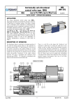
Two-way explosion proof directional
control valve type 2IRES6
NS6
WK
499 425
up to 31,5 MPa up to 30dm3/min
DATA SHEET - SERVICE MANUA
MANUAL
NUA L
11.2012
APPLICATION
The two-way directional control valve type 2IRES
2IRES6... is designed to control the
direction of the flow of liquid (oil) in a hydraulic system. The valve is designed for
use in potentially explosive atmospheres in underground mines (group I) and in
equipment working near inflammable substances in the form of gas, vapor, mist
(group II).
II The valve has been certified for intrinsic safety:
I M1 Ex ia I Ma;
II 2G Ex ia II B T4 Gb,
Ma
Gb it can work with the intrinsically safe
circuit "ia
ia"
ib"
ia or "ib
ib with maximum parameters: Ui = 15 V; Ii = 1.6 A; Ci = 0; Li = 0.
For the group II of devices power supply should have the power limit Pi,
Pi according
to the technical data table on page 2.
OVERALL DIMENSIONS
5
9
2
4
8
10
3
10
6
7
72
1
11
63
1
o-ring 15,6 x 1,78
o-ring 18,6 x 2,6
(o-ring 22,2x2,6
for 2 IRES6...M2...)
O
19
M22x1,5
(M26x1,5)
OO
O
26,5
( 31,5)
2
2
S 36
28
o-ring 30 x 2
5
41
146
DESCRIPTION OF OPERATION
To open or close oil flow is done by changing position of cone (2) in the sleeve (1). The close of the port is
secured by putting voltage on coil (3). The coil can be placed in each angle position to the solenoid sleeve. The
flow in outlet position from port 1 to port 2 is possible (version A3). It can be made by using he ball stopping the
hole in the cone (2). An optional emergency button (7) permits movement of the spool without solenoid. The
valve is equipped with explosion proof solenoid type EMSGI – 45. Solenoid is assembled with solenoid sleeve (4)
and emergency button (7). There is a coil (3) on the sleeve (4) Outside of coil mounted is socket (8) Inside the
socket are diodes as well as safety device preventing excessive current increase. Electrical connection is realize by
using plug (5). Power lead must be sealed and immobilized in both types using gland (11). Sealing rings (10)
protect the coil against external impacts and prevent from tern of coil after tightening up the nut (6)
Type 2IRES6
-1-
WK 499 425
11.2012
TECHNICAL DATA
Hydraulic fluid
Required filtration
Recommended Filtration
Nominal fluid viscosity
Viscosity range
Optimum working temperature
Relative humidity of air
Maximum pressure
Maximum flow
Weight
Supply voltage Un
Supply current In
Scope of insulation
mineral oil
up to 16 µm
up to 10 µm
37 mm 2 /s at temperature 55 oC
2,8 up to 328 mm2/s
40 up to 55ºC
up to 95%
31,5 MPa
30 dm3/min
1, 5 kg
12 V
110 mA
IP 64
ACCORDING TO DI
D I R E C T I V E 9 4/ 9 /W E
Quali ty certi ficate
fica te
Inspecti o n certi ficate
fica te
1026
102 6
FTZ
ZU 05 AT EX 0068
FT
0 068
Type of protect ion
io n
No .
II 2G
2 G Ex ia I IB T4 Gb
I M 1 Ex ia I M a
- 20 up to 60 o C
- 20 up to 40 oC
o
Ambient temperature Ta
FTZ
FT ZU 05 AT EX Q 01 3
- 20 up to 60 C
Pi
Pi
≤ 1,2 W
≤ 1,3 W
ASSEMBLY AND OPERATION REQUIREMENTS
1.
2.
3.
4.
5.
Electric connection of the valve must be
made according to electric scheme.
Conductors of valve must be meet
requirements applied in the mining
machinery.
Only skilled workers can direct connect
valve to an
an electrical system.
The plug must be supported by retains
screw.
During the period of operation must be
kept the fluid viscosity and filtration
according to requirements defined in
Service Manual
6.
In order to ensure the failure free and safe
operation must be check:
• condition
condition of the electrical connection,
• the verity proper working of the valve,
• cleanness of the hydraulic fluid.
7. Any valve repair in the mine condition is
forbidden. A damaged valve must be
supplied to the producer in order to repair.
The address of service
service is shown on the last
page of this Data sheet – Service Manual
8. A person that operates the valve has to
acquaint with Service Manual.
SCHEMES
graph
graphica
ical symbol
symbo l
2IRES6 A1...
2IRES6 A3...
electric
electr ica
ical scheme
view
iew of electr ica
ical co
c onnecti
nect ion
B1 - 0,25A
D1
1+
WK 499 425
11.2012
-
+
D2
1
2
-2
-2-
Type 2IRES6
DIMENSION OF CAVITY
1,25
v
0,5 x 45
15
13
32
2
45°
2,5
DETAIL D
9,5 max
1
O
O
9,5 max
1
O
aO
2,5
3,3 ±0,1
D
33
21
2,5
+0,05
19
1,25
L
O
C
B
A
9,5 min
0,025 - Applied to all main hole diameters and phase point
Tightening torque of valve 30 Nm.
Port
M1
M2
A
M22 x 1,5
M26 x 1,5
B
φ 23 +0,15
φ 27,4 +0,15
C
φ 28
φ 32
L
1
5
PERFORMANCE CURVES
oil viscosity ν = 41 mm2/s at temperature 50ºC
Flow curves
Type 2IRES6
-3-
WK 499 425
11.2012
HOW TO ORDER
Order coded in the way showed below should be forwarded to the manufacturer.
2IRES6
Hydraulic scheme
Scheme A1
Scheme A3
02
2
G12 Z4
*
= A1
= A3
Series number
(02-09) – connection and installation dimension unchanged
= 02
Number of position
2 position
=2
Mounting method
Port M22 x 1,5
Port M26 x 1,5
= M1
= M2
Control voltage solenoids
12V DC
= 12
Electrical connection
Plug in connector
= Z4
Sealing
NBR (for fluids on mineral oil base)
FPM (for fluids on phosphate ester base)
= no code
=V
Additional requirements in clear text
(to be advanced with the manufacturer)
Coding example:
2IRES6 A1- 02/2 M1 G12 Z4
PONAR Wadowice S.A.
ul. Wojska Polskiego 29
34-100 Wadowice
tel. +48 33 488 29 00
fax.+48 33 488 21 03
www.ponar-wadowice.pl
WK 499 425
11.2012
-4-
Type 2IRES6