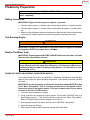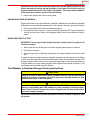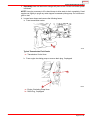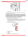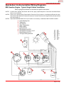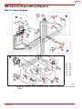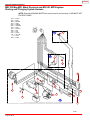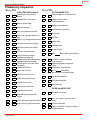
1
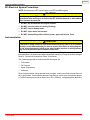
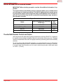
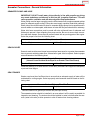
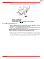
INDEX The following are registered trademarks of Brunswick Corporation: Merc, MerCathode, MerCruiser, Mercury, Mercury Marine, Quicksilver, and Ride-Guide. GASOLINE ENGINES SKI MODELS NOTICE to INSTALLER After Completing Installation, These Instructions Should Be Placed With The Product For The Owner’s Future Use. NOTICE to COMMISSIONING DEALER Predelivery Preparation Instructions Must Be Performed Before Delivering Boat To The Product Owner. Table of Contents General Information . . . . . . . . . . . . . . . . . . . . . . . 3 Notice to Boat Manufacturer/Installer . . . . . . . 3 Quicksilver Products . . . . . . . . . . . . . . . . . . . . . 4 Installation Products . . . . . . . . . . . . . . . . . . . . . 4 Torque Specifications . . . . . . . . . . . . . . . . . . . . 4 Serial Number Decal Placement . . . . . . . . . . . 4 Fuel Octane Requirements Sticker . . . . . . . . . 4 Engine Rotation . . . . . . . . . . . . . . . . . . . . . . . . . 4 Transmission . . . . . . . . . . . . . . . . . . . . . . . . . . . . 5 Installation Requirements . . . . . . . . . . . . . . . . . 6 Boat Construction . . . . . . . . . . . . . . . . . . . . . . . 6 Exhaust System . . . . . . . . . . . . . . . . . . . . . . . . . 9 Fuel Delivery System . . . . . . . . . . . . . . . . . . . 10 Battery . . . . . . . . . . . . . . . . . . . . . . . . . . . . . . . . 13 Battery Cables . . . . . . . . . . . . . . . . . . . . . . . . . 13 EFI Electrical System Precautions . . . . . . . . 14 Instrumentation . . . . . . . . . . . . . . . . . . . . . . . . . 14 Propeller Selection . . . . . . . . . . . . . . . . . . . . . . 15 Throttle/Shift Remote Control and Cables . . . . . . . . . . . . . . . . . . . . . . . . . . . . . . . 16 Seawater Connections - General Information . . . . . . . . . . . . . . . . . . . . . . . . . . . 17 Hot Water Heater Installation Information . . 18 90-860178001 APRIL 2000 Engine Installation . . . . . . . . . . . . . . . . . . . . . . . 19 Battery Cable Connection . . . . . . . . . . . . . . . . 19 Engine Mount Pre-Adjustment . . . . . . . . . . . . 20 Initial Engine Alignment . . . . . . . . . . . . . . . . . 22 Final Engine Alignment . . . . . . . . . . . . . . . . . . 22 Seawater Pickup Pump Connection . . . . . . . 24 Throttle/Shift Cable . . . . . . . . . . . . . . . . . . . . . 25 Fuel Supply Connection . . . . . . . . . . . . . . . . . 29 Audio Warning System . . . . . . . . . . . . . . . . . . 33 Electrical Connections . . . . . . . . . . . . . . . . . . . 31 Exhaust System Hoses/Tubes Connection . . . . . . . . . . . . . . . . . . . . . . . . . . . 31 Predelivery Preparation . . . . . . . . . . . . . . . . . . . 32 Battery Connection . . . . . . . . . . . . . . . . . . . . . 32 Test Running Engine . . . . . . . . . . . . . . . . . . . . 32 Boat-In-The-Water Tests . . . . . . . . . . . . . . . . . 32 Cold Weather or Extended Storage Draining Instructions . . . . . . . . . . . . . . . . . . . 33 Quicksilver Instrumentation Wiring Diagrams . . . . . . . . . . . . . . . . . . . . . . . . . . . . . . . 41 MIE Gasoline Engine Wiring Diagrams . . . . . 42 MIE Water Flow Diagram . . . . . . . . . . . . . . . . . . 47 Predelivery Inspection . . . . . . . . . . . . . . . . . . . . 48 Printed in U.S.A. - 2000, Mercury Marine Page 1 of 48 INDEX GASOLINE ENGINES SKI MODELS THIS PAGE IS INTENTIONALLY BLANK Page 2 of 48 INDEX GASOLINE ENGINES SKI MODELS General Information Notice to Boat Manufacturer/Installer Throughout this publication, “Warnings” and “Cautions” (accompanied by the International Hazard Symbol ! ) are used to alert the manufacturer / installer to special instructions concerning a particular service or operation that may be hazardous if performed incorrectly or carelessly –– Observe Them Carefully! These “Safety Alerts,” alone, cannot eliminate the hazards that they signal. Strict compliance to these special instructions when performing the service, plus “common sense” operation, are major accident prevention measures. WARNING Hazards or unsafe practices which COULD result in severe personal injury or death. CAUTION Hazards or unsafe practices which could result in minor personal injury or product or property damage. IMPORTANT: Indicates information or instructions that are necessary for proper installation and/or operation. This installation requirements manual has been written and published by Mercury Marine to aid the boat manufacturer involved in the application and installation of the products described herein. It is assumed that these personnel are familiar with marine product application and the installation procedures of these products, or like or similar products manufactured and marketed by Mercury Marine. Furthermore, it is assumed that they are familiar with, if not trained in, the recommended installation procedures of these products. It is the responsibility of the OEM to select the appropriate engine/transom/drive package (including the correct gear ratio and propeller) for a given boat. Making an appropriate selection requires knowledge of the boat (weight, length, hull design, intended use and duty cycle, desired speed, etc.) that is uniquely in the possession of the OEM. While Mercury employs people capable of assisting the OEM on such issues, the final decision rests with the OEM. Mercury recommends that any new or unique hull/power package combination be thoroughly water tested prior to sale, to verify (among other things) that the boat performs as desired, and that the engine runs in the appropriate rpm range. We could not possibly know of and advise the marine trade of all conceivable applications and installations which might be achieved, and of the possible hazards and/or results of each conceivable application or installation. We have not undertaken any such wide evaluation. Therefore, any manufacturer which, or person who, applies or installs the product in a manner which does not fulfil the requirements listed herein, first must completely satisfy themselves that neither their safety nor the product will be endangered by the application or installation procedure selected. It is recommended that a Mercury Marine Field Product Engineer be contacted for assistance if specific application or installation problems are encountered. All information, illustrations, and specifications contained in this manual are based on the latest product information available at time of publication. As required, revisions to this manual will be sent to all OEM boat companies. Page 3 of 48 INDEX GASOLINE ENGINES SKI MODELS Quicksilver Products Quicksilver gauges, remote controls, steering systems, propeller shaft couplers, etc. are available for this product. Refer to “Quicksilver Accessories Guide” for complete listing. This “Guide” is available from: Attn: Parts Department Mercury Marine W6250 W. Pioneer Road P.O. Box 1939 Fond du Lac, WI 54936-1939 Installation Products Quicksilver 2-4-C Marine Lubricant with Teflon 92-825407A3 Quicksilver Liquid Neoprene 92-25711-2 Quicksilver Perfect Seal 92-34227-1 Torque Specifications DESCRIPTION lb. ft. N·m Engine Mount Bracket Screw 48 65 Trunnion Clamping Screw and Nut 50 68 Propeller Shaft Coupling Screw and Nut 50 68 Exhaust Manifold Screw 20 27 Fuel Line Inlet Fitting lb. in. See Note. Note: Refer to Fuel Delivery System - “Special Information For All Gasoline Engines.” Serial Number Decal Placement There are three engine serial number decal strips provided with each power package. One should be used for each of the following: • Engine Specification Decal • Warranty Registration Card • Operation, Maintenance and Warranty Manual identification page. Engine Rotation Engine rotation is described when observed from the rear of the engine (transmission end) looking forward (water pump end). Engine rotation is indicated on engine specifications and serial number decal. Page 4 of 48 INDEX GASOLINE ENGINES SKI MODELS Transmission IDENTIFICATION Velvet Drive Transmissions On Velvet Drive In-Line Transmissions the gear ratio (in forward gear) is marked on transmission identification plate. Transmission output shaft rotation and propeller rotation required (in forward gear) is indicated on a decal on transmission case. Transmission rotation is described when viewed from the rear of transmission. c b a 22556 a - Transmission Identification Plate b - Gear Ratio (in Forward Gear) c - Output Flange Rotation Decal (in Forward Gear) Propeller Rotation Propeller rotation is not necessarily the same as engine rotation. Refer to the appropriate following information and drawings for specific information. IMPORTANT: Use of proper rotation propeller (specified on transmission output flange rotation decal) is critical since the transmission must be operated in forward gear selector position only to drive boat forward. If the wrong rotation propeller is installed and transmission is operated in reverse to propel the boat forward, transmission failure WILL occur. On engines which are equipped with Velvet Drive in-line, a LH propeller is required. Page 5 of 48 INDEX GASOLINE ENGINES SKI MODELS ENGINE/PROPELLER SHAFT INSTALLATION ANGLE The transmission and engine should be mounted so that the angle relative to horizontal is as shown in the installation drawings. Refer to individual installation drawings for each specific engine and transmission. Relative to horizontal, never install the engine with the front (pulley end) down. IMPORTANT: On all engines, a high angle of installation [front (pulley end) of engine up] along with low transmission oil levels can permit transmission pump cavitation on some models when operating in rough water. COUPLING The coupling is a flange type coupler (available through Quicksilver Accessories). All coupler bolts must be SAE Grade 8 (Metric Grade 10.9) or better, with a shoulder (grip length) long enough to pass through the face mating plane of couplers. All coupler bolts must be torqued to 50 lb. ft. (68 N·m). PROPELLER SHAFT DIAMETER Propeller shaft diameter should be of sufficient size for the type of application. Installation Requirements Boat Construction ENGINE BED Distance between starboard and port engine mount is 22-1/2 in. (572 mm). Engine bed must position engine so that a minimum of 1/4 in. (6 mm) up and down adjustment still exists on all 4 mounts after performing final engine alignment. This is necessary to allow for realigning engine in the future. NOTE: Although the engine mounts allow some adjustment, it is a good practice to ensure that the front and rear mount locations in the vessel are in parallel planes. This may be checked by tying a string from the left front mount location to the right rear mount location and another from right front to left rear. The strings should touch where they cross. ENGINE COMPARTMENT WARNING Boating standards (NMMA, ABYC, etc.) and Coast Guard regulations must be adhered to when constructing the engine compartment. Care must be exercised in the design and construction of the engine compartment. Seams must be located so that any rain water that may leak through the seams is directed away from the air intake system. Water that runs onto the air intake may enter the engine and cause serious damage to internal engine parts. Page 6 of 48 INDEX GASOLINE ENGINES SKI MODELS Over the last several years, engine compartments have been designed to be quieter. The most common material used to deaden the engine sound is some type of insulation material. Normally, the quieter the engine compartment is, the more insulation material used, which results in less air space inside. The less air space inside the engine compartment, the hotter the inside air temperature. Attention must be given to the air temperature that is inside this engine compartment while the engine is running or after a period of time after the engine is shut off (heat soak). Refer to the following information on Engine Compartment Ventilation. ENGINE COMPARTMENT VENTILATION General Information According to Boating standards (NMMA, ABYC, etc.) and Coast Guard regulations the engine compartment ventilation system has multiple tasks. Included are the following: 1. To supply the engine with combustion air. 2. To maintain a low temperature in the engine compartment. Fresh air should enter the engine compartment as low as possible and the heated air should be discharged from the highest point. When sufficient ventilation is not provided, too much heat can build-up inside of engine compartment and cause vapor locking. The engine will not want to restart after it has been shut off for a short period of time. If it does restart, the engine will quit when given the throttle to get the boat up on plane or to pull up a water skier. For engines utilizing fuels containing alcohol and the newer “reformulated gasolines” (See OEM Service Bulletin 95-2), proper ventilation is more critical to prevent vapor locking. If a separate air shaft (or similar) is used to provide engine compartment ventilation or additional ventilation, care must be taken to prevent seawater and spray from entering it. Combustion Air Requirements Engine compartments with natural draft ventilation must have vent openings of sufficient size and location to accomplish the tasks previously outlined. IMPORTANT: The size of ventilation openings must be increased if any auxiliary equipment is located in the engine compartment. The combustion air requirement (per engine) for the specified engines at Wide Open Throttle are given in the chart below: Engine Air Flow Requirements (Per Engine) Model Engine Air Requirements at Wide Open Throttle Physical Volume 5.7L 486 ft.3/Min. (0.229 m3/sec.) 5.3 ft.3 (150 L) 350 Mag MPI 506 ft.3/Min. (0.239 m3/sec.) 5.3 ft.3 (150 L) MX 6.2L MPI 568 ft3/Min. (0.268 m3/sec.) 5.3 ft.3 (150 L) Black Scorpion 527 ft.3/Min. (0.249 m3/sec.) 5.3 ft.3 (150 L) In addition, the pressure differential (outside engine compartment versus inside engine compartment) should not exceed 2 in. (51mm) of water (measured with a manometer) at Wide Open Throttle. Page 7 of 48 INDEX GASOLINE ENGINES SKI MODELS Compartment Temperature - Specifications Air temperatures inside of engine compartments have been measured in excess of 200° F (82° C). The long term effect to fuel system components running at these excessive temperatures is not known at this time. According to specification SAE J1223 for Marine Carburetors: “The carburetor shall be capable of operation throughout an ambient (air temperature) range from +20° to +176° F (–7° to +80° C) without failure.” Carburetors, throttle body injection (TBI) units and components for multi-port EFI systems used by MerCruiser meet this specification. Under the hottest outside air temperature condition at which the boat will be operated, the air temperature inside the engine compartment, measured at the flame arrestor, shall not exceed 176° F (80° C). Also, the temperature of the fuel being supplied to the engine shall not exceed 110° F (43° C) at any location between the fuel tank and the engine’s fuel pump. Since many factors influence engine compartment temperature, temperature measurements should always be carried out as follows. Compartment Temperature - Testing Test as follows: 1. The boat being tested shall be a standard production boat fitted as it would be for delivery to a dealer. 2. Temperature test meter used shall be of the type that can be read without opening the engine cover. 3. During the test, in Step 4, engine compartments are to remain closed. No outside air is to be forced into the engine compartment during the test and the bilge blower should not be running. 4. Engine Running and Heat Soak Test: a. Use 1 meter and 2 thermal couples. Place one thermal couple at the flame arrestor to measure the inlet air temperature. Place the second thermal couple at the fuel pump to measure the inlet fuel temperature. A third thermal couple is needed if the fuel supply line between the tank and the fuel pump is higher than the fuel pump. Place the third thermal couple at the highest point of the supply line to measure the temperature of the fuel at that point. b. Start engine to warm it up. After engine is at its normal operating temperature, run engine at 1500 rpm (in neutral gear) for 15 minutes. Record both temperature readings at 5 minute intervals. c. After 15 minutes running at 1500 rpm, shut engine off and continue to record both temperature readings at 5 minute intervals for the next 45 minutes. d. After the 45 minute heat soak test, start engine and idle (in neutral gear) for 20 minutes. Continue to record both temperature readings at 5 minute intervals. IMPORTANT: If the temperature at either location exceeds specifications, the engine compartment will need additional ventilation until both temperatures remain below these specifications. Page 8 of 48 INDEX GASOLINE ENGINES SKI MODELS Exhaust System IMPORTANT: It is the responsibility of the boat manufacturer, or installing dealer, to properly locate the engine and install the exhaust system. Improper installation may allow water to enter the exhaust manifolds and combustion chambers and severely damage the engine. Damage caused by water in the engine will not be covered by MerCruiser Warranty unless this damage is the result of defective part(s). Determine if exhaust elbow risers are required by taking measurements “a” and “b” with boat at rest in the water and maximum load aboard. Subtract (b) from (a) to find (c). If (c) is less than specified in chart, select appropriate size exhaust elbow riser kit, and exhaust extension kit if applicable, that will correctly position exhaust elbow. Model (c) = (a) Minus (b) All Models (c) Must Be 13 in. (330 mm) or More b d c a 22457 Typical Installation Shown a - From Waterline To Top Of Transom b - From Highest Point On Exhaust Elbow To Top Of Transom c - Equals (a) Minus (b) d - Waterline At (c) Rest • System must not cause excessive back pressure when measured at exhaust elbow outlets. Back pressure MUST NOT exceed 2 psi (14 kPa). Minimum exhaust hose sizes are given in chart: Minimum Exhaust Outlet Hose Size 3-1/2 in. (88.9 mm) • Exhaust hoses must be secured at each connection with two (2) hose clamps. • Exhaust hoses must be connected to exhaust elbows so that they do not restrict the flow of discharge water from the elbow. If hoses are connected incorrectly, a hot spot in the hose can occur and can eventually burn through. NOTE: A kit is available, when applicable, to reduce from the 4 in. (102 mm) to 3 in. (76 mm). Refer to the “Quicksilver Accessories Guide” for kit part number. Page 9 of 48 INDEX GASOLINE ENGINES SKI MODELS Fuel Delivery System WARNING Boating standards (NMMA, ABYC, etc.) and Coast Guard regulations must be adhered to when installing fuel delivery system. GENERAL The main concern of a boat’s fuel system is safety; this must be achieved through a technically sound installation and constant inspection. The fuel system, from the filler pipe to the fuel pump, is the same in principle for all boats. The fuel tank is an integrated component of the boat. Refer to the special information on service and maintenance that you have received from the tank manufacturer. NOTE: On Ski Boat Applications: If during testing for a particular application, you experience fuel starvation in sharp high speed turns, baffles or a fuel sump may be needed in the tank to help correct this condition. Only a few points related to function and safety are listed here. Refer to boating standards (NMMA, ABYC, etc.) and Coast Guard regulations for complete guidelines: • All connections should be on the upper side of the tank. • The drain plug at the lowest point on the tank serves to permit the removal of water and sediment. • The filler pipe outer diameter should be at least 2 in. (51 mm). • The tank breather pipe must have an inner diameter of at least 1/2 in. (13 mm) and must be fitted with a swan neck to prevent water from entering the tank. It is recommended that the exact route and length of the fuel lines be established at the first installation of the engine to prevent problems later in connecting them to the engine. All fuel lines must be well secured. The holes where the lines run through the bulkheads should be carefully rounded off or protected with rubber grommets. This prevents damage to the lines from abrasion. Page 10 of 48 INDEX GASOLINE ENGINES SKI MODELS The following, but not limited to the following, additional fuel connection related points, applying to all engines unless otherwise stated, must be considered [Refer to boating standards (NMMA, ABYC, etc.) and Coast Guard regulations for complete guidelines]: 1. Fuel tank should be mounted below carburetor level (if possible) or gravity feed may cause carburetor fuel inlet needle to unseat and flooding may result. 2. On Gasoline Engines: The maximum measured vacuum at the engine’s fuel inlet must not exceed 2 in. Hg (6.9 kPa) at idle rpm, 3000, full throttle rpm, and back at idle rpm. IMPORTANT: Vacuum reading higher than specified can cause vapor locking with some of today’s fuels. It can also cause poor engine performance because of fuel starvation. 3. Fuel pickup should be at least 1 in. (25mm) from the bottom of fuel tank to prevent picking up impurities. 4. Fuel lines used must be Coast Guard approved (USCG Type A1). Diameter of fittings and lines must not be smaller than 5/16 in. (8 mm) I.D. on 350 cid / 5.7L and Black Scorpion engines. Diameter of fittings and lines must not be smaller than 3/8 in. (10 mm) I.D. on 377 cid / 6.2L engines. 5. Larger diameter (than previously specified) lines and fittings must be used on installations requiring long lines or numerous fittings. 6. Fuel line(s) should be installed free of stress and firmly secured to prevent vibration and/ or chafing. 7. Sharp bends in fuel lines should be avoided. 8. A flexible fuel line must be used to connect fuel supply line to fuel inlet fitting on engine to absorb deflection when engine is running. SPECIAL INFORMATION ABOUT ELECTRIC FUEL PUMPS CAUTION The electric fuel pump and factory installed water separating fuel filter have been carefully designed to function properly together. Do not install additional fuel filters and/or water separating fuel filters between fuel tank and engine. The installation of additional filters may cause: • Fuel Vapor Locking • Difficult Warm-Starting • Piston Detonation Due to Lean Fuel Mixture • Poor Driveability Page 11 of 48 INDEX GASOLINE ENGINES SKI MODELS SPECIAL INFORMATION FOR ALL GASOLINE ENGINES WARNING Avoid gasoline fire or explosion. Improper installation of brass fittings or plugs into fuel pump or fuel filter base can crack casting and/or cause a fuel leak. IMPORTANT: The following information is provided to ensure proper installation of brass fittings or plugs installed into fuel pump or fuel filter base: Page 12 of 48 • Use #592 Loctite Pipe Sealant with Teflon on threads of brass fittings or plugs. DO NOT USE TEFLON TAPE. • Brass fittings or plugs should first be threaded into fuel pump or fuel filter base until finger tight. • Fittings or plugs should then be tightened an additional 1-3/4 to 2-1/4 turns using a wrench. DO NOT OVERTIGHTEN. • To prevent overtightening when installing a fuel line, the brass fittings should be held with a suitable wrench as fuel line connectors are tightened securely. INDEX GASOLINE ENGINES SKI MODELS Battery IMPORTANT: Boating industry standards (BIA, ABYC, etc.), federal standards and Coast Guard regulations must be adhered to when installing battery. Be sure battery cable installation meets the pull test requirements and that positive battery terminal is properly insulated in accordance with regulations. IMPORTANT: Engine electrical system is negative (–) ground. It is recommended (required in some states) that battery be installed in an enclosed case. Refer to regulations for your area. Select a battery that meets all of the following specifications: 1. 12-volt marine type. 2. Tapered post connector or side terminal connectors. Do not use a battery with wing nut connectors. 3. Reserve battery capacity rating of at least: Engine (cyl./type) cid (L) Minimum Required Cranking Battery Size V8 Carb 350 (5.7) 375 cca/475 mca/90 Ah V8 MPI 350 (5.7) and 377 (6.2) 550 cca/700 mca/120 Ah Battery Cables Select proper size positive (+) and negative (–) battery cables using chart. Battery should be located as close to engine as possible. IMPORTANT: Terminals must be soldered to cable ends to ensure good electrical contact. Use electrical grade (resin flux) solder only. Do not use acid flux solder as it may cause corrosion and a subsequent failure. GASOLINE ENGINES Cable Gauge Cable Length (25mm2) Up to 3-1/2 ft (1.1m) 4 3-1/2 - 6 ft (1.1-1.8m) 2 (35mm2) 6 - 7-1/2 ft (1.8-2.3m) 1 (50mm2) 7-1/2 - 9-1/2 ft (2.3-2.9m) 0 (50mm2) 9-1/2 - 12 ft (2.9-3.7m) 00 (70mm2) 12 - 15 ft (3.7-4.6m) 000 (95mm2) 15 - 19 ft (4.6-5.8m) 0000 (120mm2) Page 13 of 48 INDEX GASOLINE ENGINES SKI MODELS EFI Electrical System Precautions NOTE: All references to EFI models apply to all EFI and MPI engines. CAUTION Avoid damage to the EFI electrical system and components. Refer to the following precautions when working on or around the EFI electrical harness or when adding other electrical accessories: • DO NOT tap accessories into engine harness. • DO NOT puncture wires for testing (Probing). • DO NOT reverse battery leads. • DO NOT splice wires into harness. • DO NOT attempt diagnostics without proper, approved Service Tools. Instrumentation CAUTION If Quicksilver wiring harness is used and a fused accessory panel is to be installed (40-amp current draw maximum), be sure to connect it as shown in wiring diagram. Do not connect accessory panel at any other location as wires in wiring harness may not be of sufficient size to handle current load. We recommend the use of Quicksilver Instrumentation and Wiring harness(es). On dual station applications, oil pressure and water temperature senders (on engine) must be changed. Refer to “Quicksilver Accessories Guide” for selection. The 4 basic gauges that must be used with the engine are: • Tachometer • Oil Pressure • Water Temperature • Voltmeter Route instrumentation wiring harness back to engine, making sure that harness does not rub or get pinched. If an extension harness is required, be sure to secure connection properly. Fasten harness(es) to boat at least every 18 in. (460mm), using appropriate fasteners. Page 14 of 48 INDEX GASOLINE ENGINES SKI MODELS Propeller Selection GENERAL INFORMATION IMPORTANT: Installed propeller must allow engine to run at its specified maximum wide-open-throttle revolutions per minute (rpm). Use an accurate service tachometer to verify engine operating rpm. It is the responsibility of the boat manufacturer and/or the selling dealer to equip the power package with the correct propeller(s). Specified engine wide-open-throttle (WOT) and operating rpm range are listed in the “Operation, Maintenance and Warranty Manual” attached to the engine. Select a propeller that will allow the engine power package to operate at or near the top end of the recommended wide-open-throttle operating rpm range with a normal load. There is a change in rpm between propeller diameter or pitches that is generalized in the following chart: MIE Models Gasoline Diameter or Pitch Change RPM Change 1 Inch 150 If full throttle operation is below the recommended range, the propeller must be changed to prevent loss of performance and possible engine damage. On the other hand, operating an engine above the recommended operating rpm range will cause higher than normal wear and/or damage. After initial propeller selection, the following common problems may require that the propeller be changed to a lower pitch: • Warmer weather and greater humidity cause an rpm loss. • Operating in a higher elevation causes an rpm loss. • Operating with increased load (additional passengers, pulling skiers, etc.). For better acceleration, such as is needed for water skiing, use the next lower pitch propeller. However, do not operate at full throttle when using the lower pitch propeller but not pulling skiers. Because of the many variables of boat design, only testing will determine the best propeller for a particular application. Available propellers are listed in the “Quicksilver Accessories Guide.” See “BOAT-IN-THE-WATER TESTS, Maximum RPM Test” in the power package Installation Manual. Page 15 of 48 INDEX GASOLINE ENGINES SKI MODELS SPECIAL INFORMATION FOR GASOLINE ENGINES IMPORTANT: When selecting a propeller consider this additional information, if applicable: The engines listed in the following chart are equipped with an rpm rev-limiter that is set to an upper (or limited) rpm amount. This limit is slightly above the normal operating range of the engine and is designed to help prevent damage from excessive engine rpm. Once the rpm drop into the recommended operating rpm range, normal engine operation resumes. Engine Rev-Limiter Model Engine Recommended Operating RPM Range Rev-Limit RPM Setting 5.7L 4400-4800 4900 350 Mag MPI 4600-5000 5100 MX 6.2L 4800-5200 5350 Black Scorpion 4800-5200 5300 Throttle/Shift Remote Control and Cables Shift control and shift cable MUST position transmission shift lever EXACTLY as stated in the specific power package Installation Manual or transmission failure may occur. Damage caused to transmission as a result of improper shift lever positioning will not be covered by warranty. To ensure proper shift and throttle operation, we recommend the use of a Quicksilver remote control and cables. Refer to “Quicksilver Accessories Guide” for selection. However, if a control other than Quicksilver is to be used, control must provide a shift cable travel of 2-3/4 in. (70 mm). Page 16 of 48 INDEX GASOLINE ENGINES SKI MODELS Seawater Connections - General Information SEAWATER PICKUP AND HOSE IMPORTANT: DO NOT install water pickup directly in line with propeller as pickup may create turbulence and allow air to flow into the “propeller slipstream.” This will cause propeller ventilation and will adversely affect boat performance. Water pickup must be large enough to permit sufficient water flow to engine seawater pickup pump for adequate engine cooling. Pickup also must supply a positive head while underway. Water pickup should be located as close to seawater pickup pump inlet as possible and in an area where an uninterrupted, solid stream of water will flow past when boat is underway. Water inlet hose connections must be made with wire reinforced hose of adequate wall thickness to prevent it from collapsing from pump suction. Be sure to secure hose connections with hose clamps. Secure hose to prevent contact with any moving parts of the engine. Select the proper hose from the following chart: Seawater Pickup Hose Inner Diameter Gasoline Engines 1-1/4 in. (32 mm) SEACOCK SIZE Seacock used must have an internal cross-sectional area equal to or greater than seawater hose to prevent restricting water flow. A brass ball or gate valve is required. Select a proper seacock based on the following chart: Seacock Size (Internal Cross-Sectional Area Equal to or Greater Than Size Shown) Gasoline Engines 1-1/4 in. (32 mm) Install the seacock in an area where it will be easily accessible and supported adequately to prevent hose fatigue. SEA STRAINER Strainer used must be of sufficient size to ensure that an adequate supply of water will be maintained for cooling engine. Select a properly rated seawater strainer based on the following chart: Seawater Strainer Minimum Flow Rate 1 Gasoline Engines 1 Amounts 30 (114) listed are in gallons per minute and (liters per minute). The seawater strainer should be installed in an area where it will be easily accessible for inspection and cleaning. The strainer should be installed in water inlet hose after the seacock (water inlet valve) to allow operator to shut off water when cleaning strainer. Page 17 of 48 INDEX GASOLINE ENGINES SKI MODELS Hot Water Heater Installation Information IMPORTANT: When connecting a cabin heater or hot water heater, certain requirements must be met, including, but not limited to the following: • Supply hose (from engine to heater) and return hose (from heater to engine) MUST NOT EXCEED 5/8 in. (16 mm) I.D. (inside diameter). • Make heater connections ONLY at locations indicated in the following information. • Refer to manufacturers’ instructions for complete installation information and procedures. IMPORTANT: Do not reposition engine temperature switch; it must remain where installed by factory. CAUTION On closed cooling models, heater must be mounted lower than the fill cap on the heat exchanger. If the heater is higher than the fill cap on the heat exchanger and some coolant is lost from system, an air pocket may form in the closed cooling system. This can cause the engine to overheat. SUPPLY HOSE CONNECTION a 75473 All Engines - If Available a - Location For Hot Water Supply (Install Bayonet Fitting Here) a 71758 All Engines - Alternate Location a - Location For Hot Water Supply (Install Bayonet Fitting Here) Page 18 of 48 INDEX GASOLINE ENGINES SKI MODELS RETURN HOSE CONNECTION a 75480 a - Location for Hot Water Return (Install Bayonet Fitting Here) Engine Installation NOTICE to INSTALLER Before Starting Installation, Read “General Information” and “Installation Requirements” completely. Battery Cable Connection IMPORTANT: Engine electrical system is negative (–) ground. IMPORTANT: Before connecting battery cables, make sure that grounding stud and starter solenoid terminal are free of paint or any other material that could cause a poor electrical connection. 1. Connect negative (–) battery cable to grounding stud on flywheel housing. Tighten nut securely. a 72773 a - Negative (–) Battery Cable 2. Place rubber boot (shipped with engine) over end of positive (+) battery cable and connect to 3/8 in. (10 mm) terminal on starter. Tighten nut securely. Page 19 of 48 INDEX GASOLINE ENGINES SKI MODELS 3. Coat negative and positive battery connections with Liquid Neoprene. After Liquid Neoprene has dried, slide rubber boot over positive battery cable connection. b c a 74171 a - Negative (–) Battery Cable b - Positive (+) Battery Cable c - 90 Amp System Fuse DO NOT Remove (EFI and MPI Models) Engine Mount Pre-Adjustment 1. Remove hardware holding engine to shipping pallet. Attach a suitable sling to lifting eyes on engine. Lift engine from pallet with an overhead hoist. 2. Remove “L” shaped shipping bracket from both rear (transmission) mounts. Retorque mount bracket attaching screw to 48 lb. ft. (65 N·m). IMPORTANT: Engine mounts must be adjusted, as explained in Steps 3 and 4, to center mount adjustment and establish a uniform height on all mounts. 3. Ensure that distance from bottom of all 4 engine mounts (2 front, 2 rear) mount to bottom of trunnion equals 2-5/8 in. + 1/16 in. (10 mm + 2 mm). If not, loosen mount locking nut and turn adjusting nut in direction required to obtain proper dimension, then retighten locking nut. Be sure to leave mount positioned so that slot is forward (d). Page 20 of 48 INDEX GASOLINE ENGINES SKI MODELS 4. Loosen clamping screws and nuts on all 4 engine mount brackets to ensure the following: • Large diameter of mount trunnion extended as shown. • Mount base slotted mounting hole forward, if so designed. • Each mount base is downward. Tighten clamping screws and nuts slightly to prevent moving in or out. Mounts must be free to pivot when installing engine. e g a d c b f 70140 Front Mount e c a g f b 70645 Rear Mount a - Locking Nut b - Adjusting Nut c - Trunnion Clamp Screw(s) And Nut(s), With Lockwasher(s) d - Slot Forward e - 3/8 in. + 1/16 in. (10 mm + 2 mm) f - 2-5/8 in. + 1/16 in. (67 mm + 2 mm) g - Mount Trunnion Page 21 of 48 INDEX GASOLINE ENGINES SKI MODELS Initial Engine Alignment 1. Lift engine into boat and position on engine bed so that transmission output flange and propeller shaft coupler are visibly aligned (no gap can be seen between coupling faces when butted together). Adjust engine bed height, if necessary, to obtain proper alignment. DO NOT use mount adjustments to adjust engine position at this time. IMPORTANT: Engine bed must position engine so that a minimum of 1/4 in. (6 mm) up and down adjustment still exists on all 4 mounts after performing final alignment. This is necessary to allow for final engine alignment. 2. Ensure that all 4 mounts are still positioned properly, then fasten mounts to engine bed with 3/8 in. (10 mm) diameter lag screws (of sufficient length) and flat washers. Tighten lag screws securely. 3. Disconnect overhead hoist and remove sling. Final Engine Alignment IMPORTANT: Engine alignment MUST BE RECHECKED with boat in the water, fuel tanks filled and with a normal load onboard. Engine must be aligned so that transmission and propeller shaft coupling centerlines are aligned and coupling faces are parallel within .003 in. (0.07 mm). This applies to installations with solid couplings as well as flexible couplings. 1. Check mating faces on transmission output flange and propeller shaft coupler to make sure they are clean and flat. 2. Check that coupling centerlines align by butting propeller shaft coupler against transmission output flange. Shoulder on propeller shaft coupler face should engage recess on transmission output flange face with no resistance. NOTE: Some propeller shaft couplers may not have a shoulder on mating face. On these installations, use a straight edge to check centerline alignment. 3. Check for angular misalignment by hand holding coupling faces tightly together and checking for a gap between coupling faces with a .003 in. (0.07 mm) feeler gauge at 90° intervals. INCORRECT INCORRECT CORRECT 22457 Page 22 of 48 INDEX GASOLINE ENGINES SKI MODELS 4. If coupling centerlines are not aligned or if coupling faces are more than .003 in. out of parallel, adjust engine mounts. a. TO ADJUST ENGINE UP OR DOWN: Loosen locking nut (a) on mounts requiring adjustment and turn adjusting nuts in desired direction to raise or lower. IMPORTANT: Both front mount (or rear mount) adjusting nuts must be turned equally to keep engine level from side to side. c a b 70645 a - Locking Nut b - Adjusting Nut c - Clamping Screw(s) and Nut(s), with Lockwasher(s) b. TO MOVE ENGINE TO THE LEFT OR RIGHT: Loosen clamping screws and nuts on all 4 mount brackets and move engine to the left or right as necessary to obtain proper alignment. A small amount of adjustment can be obtained with slot on front end of some mounts. Loosen lag screws (which fasten mounts to engine bed) and move engine as required. Retighten lag screw securely. NOTE: Some rear mounts have one (1) clamping screw and nut on each side. IMPORTANT: Large diameter of mount trunnion MUST NOT extend over 1-3/4 in. (45 mm) from mount brackets on any of the mounts. 5. After engine has been properly aligned, secure engine mounts as shown. 6. Torque clamping screws and nuts on all 4 mount brackets to 50 lb-ft (68 Nm). 7. Tighten locknuts on all 4 mounts securely. Page 23 of 48 INDEX GASOLINE ENGINES SKI MODELS 8. Bend one of the tabs on tab washer down onto flat of adjusting nut. d a a b c 70646 a b c d - Clamping Screws and Nuts - Locknut - Tab On Tab Washer - 1-3/4 in. (45 mm) 9. Connect propeller shaft coupler to transmission output flange. Secure coupling together with bolts, lockwashers and nuts. Torque to 50 lb-ft (68 Nm). Seawater Pickup Pump Connection 1. Remove shipping cap. Connect seawater inlet hose to inlet fitting (bottom hose) on seawater pump. a a - Seawater Inlet Hose Page 24 of 48 75533 INDEX GASOLINE ENGINES SKI MODELS Throttle/Shift Cable Lubricate cable ends and barrels and then attach to engine and transmission. IMPORTANT: When installing throttle cable, be sure that cables are routed in such a way as to avoid sharp bends and/or contact with moving parts. DO NOT fasten any items to throttle cable. ATTACHING/ADJUSTING THROTTLE CABLE - CARBURETED MODELS 1. Lubricate cable ends and barrels. 2. Place remote control throttle lever in idle position and attach cable end guide to carburetor throttle lever as shown. 3. Grasp cable behind barrel and push lightly as shown. Adjust cable barrel to align hole with anchor stud, then slide barrel onto stud. d c e b g a d h f 22552 a b c d e f g h - Cable End Guide - Throttle Lever Stud - Elastic Stop Nut and Washer - Spacer - Cable Barrel - Anchor Stud - Washer - Elastic Stop Nut Page 25 of 48 INDEX GASOLINE ENGINES SKI MODELS ATTACHING/ADJUSTING THROTTLE CABLE - EFI MODELS 1. Place remote control handle in neutral idle position. 2. Remove flame arrestor. 3. Attach cable to the lowest hole on the throttle body unit following cable manufacturer’s instructions. 4. Install cable end guide on throttle lever, then push cable barrel end lightly toward throttle lever end. (This places a slight preload on shift cable to avoid slack in cable when moving remote control lever.) Adjust barrel on throttle cable to align with hole in anchor plate. Position cable as shown. a c b 75806 Throttle Body EFI a b c 74838 Black Scorpion a - Throttle Lever b - Anchor Plate c - Throttle Cable 5. Secure throttle cable with hardware as shown and tighten securely. Page 26 of 48 INDEX GASOLINE ENGINES SKI MODELS ATTACHING/ADJUSTING SHIFT CABLE - ALL MODELS IMPORTANT: Velvet Drive Transmission Warranty is jeopardized if the shift lever poppet ball or spring is permanently removed, if the shift lever is repositioned or changed in any manner or if remote control and cable do not position shift lever correctly. F a N R e d F b R c 22457 a b c d - Transmission Shift Lever - Shift Lever MUST BE Over This Letter When Propelling Boat FORWARD - Shift Lever MUST BE Over This Letter When Propelling Boat IN REVERSE - Poppet Ball MUST BE Centered in Detent Hole for Each F-N-R Position (Forward Gear Shown) e - Install Shift Lever Stud in This Hole, If Necessary, To Center Poppet Ball in Forward and Reverse Detent Holes IMPORTANT: When installing shift cables, be sure that cables are routed to avoid sharp bends and/or contact with moving parts. All bends must make greater than an 8 inch (203 mm) radius. DO NOT fasten any items to shift cables. NOTE: Refer to shift cable manufacturer’s instructions for adjusting the cable. Shift lever must be positioned as stated in the preceding steps. c b a 74845 a - Throttle Lever Stud b - Cable End c - Locknut Page 27 of 48 INDEX GASOLINE ENGINES SKI MODELS ROUTING OF SHIFT CABLES - BLACK SCORPION 1. Shift Cable - Route shift cable from the starboard to the port side of engine and then between intake manifold and elbow. Position cable so it will not interfere with flame arrestor. a b 74833 a - Sta-Straps b - Shift Cable Fuel Supply Connection CAUTION Remove plastic plug from fuel inlet hole in casting. Apply #592 Loctite Pipe Sealant with Teflon to threads of fuel inlet line connector. DO NOT USE TEFLON TAPE. To prevent cracking the casting and/or fuel leaks, turn inlet connector in by hand until finger tight, then tighten connector to 1-3/4 to 2-1/4 turns with wrench. DO NOT OVERTIGHTEN. Inspect for fuel leaks. IMPORTANT: A flexible fuel line must be used to connect fuel line to engine to absorb deflection when engine is running. CAUTION Ensure that the inlet hose to fuel pump does not interfere with drive belts. 1. Install barbed fuel line fittings (obtain locally) in water separating fuel filter adapter. a b 22551 a - Inlet b - Outlet Page 28 of 48 INDEX GASOLINE ENGINES SKI MODELS 2. 5.7L Model if remote mounting water separating fuel filter: Install inverted flare swivel (provided) into base of fuel pump. Finger tighten and then grip hex fitting on end of fuel pump with wrench while tightening swivel an additional 1-3/4 to 2-1/4 turns with a wrench. a 75523 a - Fuel Pump Fitting 3. Remove shipping cap from fuel fitting on water separating fuel filter bracket. NOTE: Mount water separating fuel filter in a location that allows easy removal and installation. 4. Attach fuel line to water separating fuel filter adapter. a 70573 a - Water Separating Fuel Filter Adapter Page 29 of 48 INDEX GASOLINE ENGINES SKI MODELS Audio Warning System 1. Install audio warning system horn as follows: a. Select a location for audio warning horn which meets all of the following: • horn can be easily heard yet is out of sight. • Accessible for installation or maintenance. • horn will not get wet. • Where the 18 in. (457 mm) long PURPLE wire can be connected to an “I” terminal (terminal with PURPLE wire attached to it) on one of the gauges or to a 12 volt source on switched side of ignition switch. WARNING horn is not external ignition proof, therefore, DO NOT mount horn in engine or fuel tank compartments as this would be a fire or explosion hazard. b. Mount horn in desired location. Secure horn to wire bundle with sta-strap provided. c. Connect PURPLE wire from horn to any “I” terminal or ignition switch. Tighten connection securely. (Refer To Wiring Diagram). d. Connect TAN/BLUE wire from horn to TAN/BLUE wire from instrument harness (refer to Wiring Diagram). e. Place the small (transparent) decals on the bottom of the water temperature gauge and the oil pressure gauge. f. Place the large decal on the instrument panel or other appropriate location in easy view of the operator. ALARM INDICATES LOW OIL OR OVERHEATING a APPLY THE PROPER DECAL TO THE DASHBOARD OR OTHER APPROPRIATE LOCATION: b AUDIO WARNING HORN WILL SOUND WHEN: 1. ENGINE OIL PRESSURE IS TOO LOW, 2. ENGINE WATER TEMP. IS TOO HOT, OR 3. TRANSMISSION TEMPERATURE IS TOO HOT. TO TEST THE AUDIO WARNING HORN: TURN KEY TO ON POSITION (ENGINE OFF) 75434 a - Small Decal (Transparent) b - Large Decal 2. Test audio warning system as indicated on dashboard decal. Page 30 of 48 INDEX GASOLINE ENGINES SKI MODELS Electrical Connections 1. Connect instrumentation wiring harness to engine and secure with clamp. a 75532 a - Instrumentation Wiring Harness Connection Exhaust System Hoses/Tubes Connection 1. Exhaust hoses/tubes must be connected to exhaust elbows so that they do not restrict the flow of discharge water from the elbow. If hoses/tubes are connected incorrectly, a hot spot in the hose/tube can occur, and can eventually burn through. 2. Exhaust hoses/tubes should be secured at each connection with at least 2 hose clamps. a b 22032 a - Correct b - Incorrect IMPORTANT: S-pipes must be routed under the transmission mounts. a b 74832 a - S-Pipe b - Transmission Mount Page 31 of 48 INDEX GASOLINE ENGINES SKI MODELS Predelivery Preparation NOTICE to INSTALLER Before starting Predelivery, read “General Information” and “Installation Requirements” completely. Battery Connection IMPORTANT: Engine electrical system is negative (–) ground. 1. Connect engine positive (+) battery cable (usually red) to positive (+) battery terminal. 2. Connect engine negative (–) battery cable (usually black) to negative (–) battery terminal. 3. Make sure that all battery terminal connections are tight and then coat connections and terminals with a battery terminal anti-corrosion spray to help retard corrosion. Test Running Engine WARNING If engine is to be tested on land, propeller must be removed. IMPORTANT: If engine is to be tested on land, water must be supplied to seawater pickup pump. DO NOT run engine above 1500 rpm. Boat-In-The-Water Tests IMPORTANT: Engine alignment MUST BE CHECKED with boat in the water, fuel tanks filled and with a normal load onboard. CAUTION Avoid engine damage. Ensure that cooling water is supplied to the engine if it will be run with boat out of the water. See instructions in the Operation, Maintenance and Warranty Manual entitled “Flushing Cooling System,” for instructions on connecting flush device. ENGINE IDLE SPEED ADJUSTMENT (CARBURETED MODELS) The engine should idle at rpm (as specified in “Operation, Maintenance and Warranty Manual”) with engine at normal operating temperature. If idle speed is incorrect, proceed as follows: IMPORTANT: In order to properly set idle speed, the ignition module MUST BE locked in the “Base Timing Mode.” This is necessary because of the “Idle Speed Control” feature that exists in the ignition module. This must be done before the key switch is turned to the ON or START position. 1. Connect a shop tachometer to engine. 2. Using a jumper wire, connect the ignition system “Timing Lead” (PUR/WHT wire) to a good engine ground (–). This locks the ignition module into the “Base Timing Mode.” Refer to “Engine Wiring Harness” diagram in this manual. 3. Start engine and place the remote control lever in NEUTRAL, idle position. 4. Adjust idle speed to 650 rpm. 5. Stop engine. Readjust cable barrel and reinstall the throttle cable. Page 32 of 48 INDEX GASOLINE ENGINES SKI MODELS IMPORTANT: Be sure to disconnect the jumper wire from the ignition system test lead before attempting to resume normal operations. If the jumper wire is left in place, the ignition module will operate in the “Base Timing Mode.” This means that the additional timing advance features would not be functioning. 6. Remove the jumper wire from the timing lead. ENGINE IDLE SPEED (EFI MODELS) Engine should idle at rpm (as specified in Operation, Maintenance and Warranty Manual) with engine at normal operating temperature. If idle speed is incorrect, proceed as follows: 1. Ensure that throttle cable has been adjusted properly. 2. If idle speed is still not correct, it may be necessary to perform EFI System Diagnostic Tests on the idle circuit. Refer to the appropriate MerCruiser Service Manual for procedures. WIDE-OPEN-THROTTLE TEST IMPORTANT: To run engine at full throttle before the break-in period is complete, follow this procedure. 1. Start engine and run at idle rpm until normal operating temperature is reached. 2. Run boat up on plane. 3. Advance engine rpm (in 200 rpm increments) until engine reaches its maximum rated rpm. To test if the correct propeller has been installed, operate boat (with normal load on board) at WOT and check rpm with an accurate tachometer. Engine rpm should be near top of the specified range so that under a heavy load engine speed will not fall below specifications. If engine speed is too high, replace propeller with a higher pitch propeller. Normally, a 150 rpm change exists between propeller pitches. Cold Weather or Extended Storage Draining Instructions CAUTION If boat is to remain in water after draining, seawater inlet hose must be removed and plugged to prevent a syphoning action that may occur, allowing seawater to flow from the drain holes or removed hoses. CAUTION Seawater section of cooling system MUST BE COMPLETELY drained for winter storage, or immediately after cold weather use, if the possibility of freezing temperatures exist. Failure to comply may result in trapped water causing freeze and/or corrosion damage to engine. IMPORTANT: Boat must be as level as possible to ensure complete draining of cooling system. Page 33 of 48 INDEX GASOLINE ENGINES SKI MODELS CARBURETED MODELS 1. Ensure engine is as level as possible to ensure complete draining of cooling system. 2. Remove drain plugs from following locations: a. Port Side - cylinder block. CAUTION Avoid product damage. Do not disturb the Y-fitting when removing the drain plug. There is an ignition control “Knock Sensor” in the upper hole of the fitting. This sensor must not be loosened or removed. It is tightened to a critical specification at the factory. b. Starboard Side - Y-fitting. a 75438 a - Y-fitting c. Bottom of exhaust manifolds. a a - Exhaust Manifold Drain Location Page 34 of 48 75018 INDEX GASOLINE ENGINES SKI MODELS 3. Repeatedly clean out drain holes using a stiff piece of wire. Do this until entire system is drained. NOTE: It may be necessary to lift or bend hoses to allow water to drain completely. Crank engine over slightly to purge any water trapped in seawater pickup pump. Do not allow engine to start. 4. Loosen hose clamps and remove the following hoses: a. From transmission cooler. a 75510 Typical Transmission Fluid Cooler a - Transmission Cooler Hose b. From engine circulating pump or remove drain plug, if equipped. a b 76038 a - Engine Circulating Pump Hose b - Drain Plug, if equipped Page 35 of 48 INDEX GASOLINE ENGINES SKI MODELS c. From water inlet hose (bottom) from seawater pickup pump. 75533 a a - Seawater Inlet Hose 5. After cooling system has been drained completely, install drain plugs, reconnect hoses and tighten all hose clamps securely. IMPORTANT: MerCruiser recommends that propylene glycol (a nontoxic and environmentally safe) antifreeze be used in the seawater section of the cooling system for cold weather or extended storage. Make sure that the propylene glycol antifreeze contains a rust inhibitor and is recommended for use in marine engines. Be certain to follow the propylene glycol manufacturer’s recommendations. 6. For additional assurance against freezing and rust, follow these steps. a. Remove the thermostat housing and thermostat. b. Fill the engine seawater cooling system with a mixture of antifreeze and tap water. Follow the manufacturer’s recommendation to protect engine to the lowest temperature that it will be exposed to during cold weather or extended storage. c. Reinstall thermostat and cover. d. Torque screws with lockwashers to 30 lb. ft. (41 N·m). a b c d e 74493 a b c d e Page 36 of 48 - Thermostat Housing - Gasket - Thermostat - Spacer - Thermostat Housing-to-Intake Manifold Gasket INDEX GASOLINE ENGINES SKI MODELS EFI AND MPI MODELS 1. Ensure engine is as level as possible to ensure complete draining of cooling system. 2. Remove drain plugs from the following locations: a. Port Side - cylinder block. CAUTION Avoid product damage. Do not disturb the Y-fitting when removing the drain plug. There is an ignition control “Knock Sensor” in the upper hole of the fitting. This sensor must not be loosened or removed. It is tightened to a critical specification at the factory. b. Starboard Side - Y-fitting. a a - Y-fitting c. Fuel cooler. d. Bottom of exhaust manifolds. c b a 75081 a - Cylinder Block Drain Location (port side) b - Fuel Cooler Drain Location c - Exhaust Manifold Drain Location Page 37 of 48 INDEX GASOLINE ENGINES SKI MODELS 3. Repeatedly clean out drain holes using a stiff piece of wire. Do this until entire system is drained. NOTE: It may be necessary to lift or bend hoses to allow water to drain completely. Crank engine over slightly to purge any water trapped in seawater pickup pump. Do not allow engine to start. 4. Remove hoses from the following locations: a. Water inlet hose (bottom) from seawater pump. a 75533 a - Seawater Inlet Hose b. Hose from transmission cooler. a 75510 Typical Transmission Fluid Cooler a - Transmission Cooler Hose Page 38 of 48 INDEX GASOLINE ENGINES SKI MODELS c. From engine circulating pump or remove drain plug, if equipped. a b 76038 a - Engine Circulating Pump Hose b - Drain Plug, if equipped 5. After cooling system has been drained completely, install drain plugs, reconnect hoses and tighten all hose clamps securely. IMPORTANT: MerCruiser recommends that propylene glycol (a nontoxic and environmentally safe) antifreeze be used in the seawater section of the cooling system for cold weather or extended storage. Make sure that the propylene glycol antifreeze contains a rust inhibitor and is recommended for use in marine engines. Be certain to follow the propylene glycol manufacturer’s recommendations. 6. For additional assurance against freezing and rust, follow these steps. a. Remove the thermostat housing and thermostat. b. Fill the engine seawater cooling system with a mixture of antifreeze and tap water. Follow the manufacturer’s recommendation to protect engine to the lowest temperature that it will be exposed to during cold weather or extended storage. c. Reinstall thermostat and cover. d. Torque screws with lockwashers to 30 lb. ft. (41 N·m). a b c d e a b c d e 74493 - Thermostat Housing - Gasket - Thermostat - Spacer - Thermostat Housing-to-Intake Manifold Gasket Page 39 of 48 INDEX GASOLINE ENGINES SKI MODELS THIS PAGE IS INTENTIONALLY BLANK Page 40 of 48 INDEX GASOLINE ENGINES SKI MODELS Quicksilver Instrumentation Wiring Diagrams MIE Gasoline Engine - Typical Single Station Installation Refer to gauge manufacturer’s instructions for specific connections. NOTE 1. Connect Wires Together with Screw and Hex Nut; Apply Liquid Neoprene to Connection and Slide Rubber Sleeve over Connection. NOTE 2. Power for a Fused Accessory Panel May Be Taken from This Connection. Load Must Not Exceed 40 Amps. Panel Ground Wire Must Be Connected to Instrument Terminal That Has an 8-Gauge BLACK (Ground) Harness Wire Connected to it. NOTE 3. Taped back BROWN-WHITE wire may be used for an accessory. LOAD MUST NOT EXCEED 5 AMPS. a b c d e f g h i j - Audio Warning horn - Tachometer - Oil Pressure - Water Temperature - Battery Meter - Ignition Switch - Read/Observe NOTE 1 - Read/Observe NOTE 1 and 2 - Read/Observe NOTE 3 - To Engine Wiring Harness BLK BLU BRN GRY GRN ORN PNK PUR RED TAN WHT YEL LIT DRK j a b c d = = = = = = = = = = = = = = BLACK BLUE BROWN GRAY GREEN ORANGE PINK PURPLE RED TAN WHITE YELLOW LIGHT DARK e f h g i 73371 Page 41 of 48 INDEX GASOLINE ENGINES SKI MODELS MIE Gasoline Engine Wiring Diagrams MIE 5.7L Inboard Engines 1 A C 3 2 1 4 3 2 3 2 1 D B 9 1 4 8 7 2 BLK BLU BRN GRY GRN ORN PNK PUR RED TAN WHT YEL LIT DRK = = = = = = = = = = = = = = Black Blue Brown Gray Green Orange Pink Purple Red Tan White Yellow Light Dark 3 5 6 75754 NOTE: BROWN-WHITE wire may be used for an Accessory. LOAD MUST NOT EXCEED 5 AMPS. Page 42 of 48 INDEX GASOLINE ENGINES SKI MODELS A - Ignition Components 1 - Distributor 2 - Timing Lead 3 - Knock Sensor 4 - Ignition Coil B - Starting, Charging and Choke Components 1 - Alternator 2 - Electric Choke 3 - Ground Plug 4 - Starter Motor 5 - Oil Pressure Switch 6 - Fuel Pump 7 - Circuit Breaker 8 - Neutral Safety Switch 9 - Starter Slave Solenoid C - Audio Warning Components 1 - Oil Pressure Switch 2 - Water Temperature Switch 3 - Transmission Temperature Switch D - Instrumentation Components 1 - Oil Pressure Sender 2 - Water Temperature Sender 3 - See NOTE below Page 43 of 48 INDEX GASOLINE ENGINES SKI MODELS MIE 350 Mag MPI, Black Scorpion and MX 6.2L MPI EnginesStarting and Charging System Harness NOTE: Taped back BROWN-WHITE wire may be used for an Accessory. LOAD MUST NOT EXCEED 5 AMPS. BLK BLU BRN GRY GRN ORN PNK PUR RED TAN WHT YEL LIT DRK = = = = = = = = = = = = = = BLACK BLUE BROWN GRAY GREEN ORANGE PINK PURPLE RED TAN WHITE YELLOW LIGHT DARK A B 1 1 2 a 5 6 1 3 c 4 7 2 C b 76062 Page 44 of 48 INDEX GASOLINE ENGINES SKI MODELS A - Audio Warning Components 1 - Transmission Temperature Switch B - Instrumentation Components 1 - Oil Pressure Sender 2 - Wire Not Used C - Charging and Starting Components 1 - Alternator 2 - Ground Stud 3 - Starter 4 - 90 Amp Fuse (DO NOT REMOVE) 5 - Circuit Breaker 6 - Starter Slave Solenoid 7 - Neutral Safety Switch a - Positive Power Wire To EFI System Harness b - Harness Connector To EFI System Harness c - Auxiliary Tachometer Lead Page 45 of 48 INDEX GASOLINE ENGINES SKI MODELS MIE 350 Magnum MPI, Black Scorpion and MX 6.2L MPI Engines Fuel and Ignition System Harness NOTE: All BLACK wires with a ground symbol are interconnected within the EFI system harness. NOTE: Component position and orientation shown is arranged for visual clarity and ease of circuit identification. 1 2 3 4 5 6 7 8 9 1011- Fuel Pump Distributor Coil Knock Sensor (KS) Module Data Link Connector (DLC) Manifold Absolute Pressure (MAP) Sensor Idle Air Control (IAC) Throttle Position (TP) Sensor Engine Coolant Temperature (ECT) Sensor Electronic Control Module (ECM) Fuel Pump Relay BLK BLU BRN GRY GRN ORN PNK PUR RED TAN WHT YEL LIT DRK = = = = = = = = = = = = = = BLACK BLUE BROWN GRAY GREEN ORANGE PINK PURPLE RED TAN WHITE YELLOW LIGHT DARK 12- Ignition/System Relay 13- Fuse (15 Amp) Fuel Pump, Fuse (15 Amp) ECM/DLC/Battery,Fuse (10 Amp) ECM/Injector/Ignition/Knock Module 14- Harness Connector To Starting/Charging Harness 15- Positive (+) Power Wire To Engine Circuit Breaker 16- Shift Plate (Not used on Ski models) 17- Oil Pressure (Audio Warning System) 18- Gear Lube Bottle (Not used on Ski models) 19- Fuel Pressure Switch 20- Water Temperature Sender 19 6 18 17 20 7 10 8 16 5 21 9 4 13 12 14 11 15 (–) (+) 1 3 2 76064 Page 46 of 48 INDEX GASOLINE ENGINES SKI MODELS MIE Water Flow Diagram Gasoline Engines with Seawater (Raw-Water) Cooling System ALL V8 350 AND 377 CID ENGINES NOTE: Certain components in the following diagram may look different than on your particular power package, but the water flow paths remain similar on all engines. 1 - Seawater Intake 2 - Seawater Pump 3 - Transmission Cooler 4 - Fuel Cooler (EFI Models) 5 - Thermostat Housing and Cover Assembly 6 - Engine Water Circulating Pump 7 - Engine Block and Cylinder Head Assembly 8 - Exhaust Manifold, Typical 9 - Restrictor Gasket 10 - Exhaust Elbow Assembly, Typical 11 - Water Flow Overboard 1 3 11 2 10 5 9 7 4 8 6 75149 Page 47 of 48 INDEX GASOLINE ENGINES SKI MODELS Predelivery Inspection Not Check/ Applicable Adjust Not Check/ Applicable Adjust CHECK BEFORE RUNNING Drain plug in and petcocks closed Seawater inlet valve open ON THE WATER TEST Engine alignment (Inboards only) Starter neutral safety switch operation Engine mounts tight Water pump operation Engine alignment Instruments(s) operation Drive unit fasteners torqued Fuel leaks Power trim cylinders fasteners tight Battery fully charged and secured Oil leaks Water leaks All electrical connections tight Exhaust leaks Exhaust system hose clamps tight All fuel connections tight Ignition timing Idle Correct rotation propeller (installed and torqued) Throttle, shift and steering system fasteners tightened properly Throttle plates open and close completely Crankcase oil level Power trim oil level RPM, within specifications Forward - Neutral - Reverse gear operation Steering operation throughout range Acceleration from idle rpm WOT RPM within specifications (in forward gear) Stern drive unit oil level Power trim operation Power steering fluid level Trim tab adjustment Closed cooling level Boat handling Transmission fluid level AFTER ON WATER TEST Alternator belt tension Propeller nut torque Seawater pickup pump belt tension Power steering pump belt tension Fuel, oil, coolant, water and fluid leaks Audio warning system operation Oil and fluid levels Apply Quicksilver Corrosion Guard to engine package Page 48 of 48