1
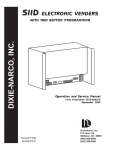
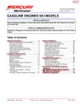
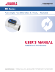
IPR-150
INSTALLATION
GUIDE
150KVA Three-Phase
Release 1.0
USER MANUAL
TABLE OF CONTENTS
INTRODUCTION ................................................................................................................................................... 4
Audience..........................................................................................................................................................................4
Related Documentation ..................................................................................................................................................4
Support ............................................................................................................................................................................4
Specifications ..................................................................................................................................................................4
SAFETY ................................................................................................................................................................ 6
RECEIVING ........................................................................................................................................................... 6
DESCRIPTION ...................................................................................................................................................... 7
Cooling.............................................................................................................................................................................7
Front View .......................................................................................................................................................................8
Lifting Provisions ...........................................................................................................................................................10
Physical Dimensions ......................................................................................................................................................10
BYPASS SWITCH ................................................................................................................................................ 11
INTEGRATED DGC ............................................................................................................................................. 12
INSTALLING THE SYSTEM .................................................................................................................................. 14
ENERGIZING THE UNIT ...................................................................................................................................... 19
PROVISIONING THE UNIT .................................................................................................................................. 19
MAINTENANCE ................................................................................................................................................. 20
APPENDIX A: MECHANICAL SPECIFICATIONS .................................................................................................... 21
GRIDCO SYSTEMS
Copyright © 2014
2
IPR-150
INSTALLATION GUIDE (Draft)
INTRODUCTION
This document describes how to install the Gridco Systems 150kVA 3-phase In-Line Power Regulator (IPR). The
IPR-150 connects in-line along a low voltage feeder and provides continuous multi-function 3-phase power
control, including dynamic and precise load voltage regulation, reactive power compensation and harmonic
cancellation during both forward and reverse power flows.
Audience
This document is intended for trained and qualified personnel responsible for installing transformers and
related equipment in underground distribution systems, as well as Engineering and utility-standards personnel.
Related Documentation
For more information, see these documents:
Table 1: Related Documentation
Document
Description
IPR Operations Guide
Describes how to use the Gridco Systems FCT to configure and manage
the IPR.
DNP3 Device Profile for IPR-50
Describes the DNP3 points that you can use to configure and manage the
system.
Release Notes
Lists known issues and workarounds (where applicable) for the In-Line Power
Regulator, Distributed Grid Controller (DGC), and Field Configuration Tool
(FCT).
Support
For technical assistance and replacement parts, contact Gridco Systems Customer Support at 1-844-4GRIDCO
(1-844-447-4326) or email [email protected].
Specifications
The following table describes key IPR-150 specifications. Additional information is described on the IPR
nameplate.
Table 2: Specifications
Parameters
Description
Type
Three phase, 50 Hz
Power Rating
150kVA
GRIDCO SYSTEMS
Copyright © 2014
4
IPR-150
INSTALLATION GUIDE (Draft)
Parameters
Description
Mounting
Standalone pad or pedestal mount
Input & Output Voltage
400/230 VAC
Source Voltage
400/230 VAC Nominal
Source Voltage Range
-27% to +30% of Nominal
Load Voltage Regulation
Boost/Buck up to ±8.4% of Nominal; ±0.5% accuracy;
Programmable set point or dead-band
VAr Compensation Range
10% of rating (expandable), leading/lagging; Programmable
VAr or PF set point
Harmonic Correction
3 to 15 , odd order; Programmable source current & load
voltage enable/disable
Harmonic Distortion
Voltage THD < 3%; Current TDD < 5%
Efficiency
> 99%
Cooling
Passive (air)
Enclosure
IP65
Noise
< 35 dB
Operating Temperature
-40° to +50° C
Operation/Management
Autonomous, local, remote
Communication (via DGC)
DNP 3.0, Secure Web Services, IEC 60870-101/104 (future),
IEC 61850 (future)
Dimensions
2070mm (width) x 1439mm (height) x 661mm (depth)
Weight
Approximately 771 kg (1700lbs.)
Cooling
Passive, Natural Convection
Coating
Complies with IEEE C57.12.00
Enclosure Rating
NEMA 4 / NEMA 4X (optional)
Lifetime
25 years, no maintenance
GRIDCO SYSTEMS
rd
th
Copyright © 2014
5
IPR-150
INSTALLATION GUIDE (Draft)
SAFETY
The following guidelines help ensure your safety and protect the system from damage. However, the list is not
all inclusive so please take appropriate precautions.
•
•
•
•
•
•
•
•
•
•
•
•
Refer to your utility safety standards for power equipment.
The units should be installed, operated, and serviced only by qualified and competent personnel.
The unit weighs appropriately 771 kg (1700lbs), so appropriate equipment and number of personnel must
be used to install the unit. Cranes must utilize the unit’s lifting boss provisions.
The unit must be installed with adequate venting and clearance on all sides. Failure to provide 61cm (24”)
of clearance on all sides of the unit may result in equipment damage or personal injury.
The unit must be properly grounded before energizing the system. Failure to properly ground the unit may
result in equipment damage, personal injury, or death.
The front compartments are protected from unauthorized access. Doors with provision for securing with
padlock accept up to 9.525mm (3/8”) shackle or other equivalent locking mechanism. Failure to secure the
doors may result in access by unauthorized personnel and can cause severe injury, death or equipment
damage.
Ensure the unit is de-energized prior to servicing. Failure to do so may result in equipment damage,
property damage, personal injury, or death.
Should damage to the unit be observed, de-energize and remove the unit from service until repairs are
completed by qualified personnel and the unit is verified as operational.
Before proceeding with connecting power or working on the system, check your work area for possible
hazards.
Do not work alone whenever potentially hazardous conditions exist.
Ensure that you have nameplate information handy when communicating with Gridco Systems regarding
the unit.
The surfaces of IPR heat sinks inside the main enclosure can get extremely hot. Be sure to take appropriate
precautions when handling or servicing the unit.
RECEIVING
Each unit ships fully assembled, ready to install, and anchored onto the pallet by four shipping brackets. The
unit is wrapped with an environmental bag and encapsulated within a crate for shipping. The fully-assembled
unit weighs approximately 771 kg (1700lbs.) and must be moved with equipment of appropriately rated
capacity (2000lbs. capacity rating recommended) utilizing the lifting provisions located on each corner of the
enclosure. Carefully inspect the unit prior to installation to ensure that no damage has occurred during
shipment. If damage is apparent, do not install the unit and contact Gridco Systems.
GRIDCO SYSTEMS
Copyright © 2014
6
IPR-150
INSTALLATION GUIDE (Draft)
DESCRIPTION
The IPR-150 is an IP-65 enclosure constructed of 12-gauge steel and aluminum finished in weather resistant
light tan (RAL 7035) powder coat; a stainless steel option is available for harsh environments. Doors on the
front of the unit are secured with padlock provision and provide access to internal components, including:
•
Conductor Rack – Enables connection to source and load for each phase. Primary and secondary cables
connect to the unit from below through openings in the pad.
•
Phase-specific IPRs – IPRs that provide multi-function power control per phase. There are 3 integrated
IPRs (1 IPR per phase).
•
Digital Grid Controllers (DGC) – Provides management access and data acquisition for each phasespecific IPR. There are 3 integrated DGCs (1 DGC per phase-specific IPR).
The following figure shows the location of the integrated phase-specific IPRs, DGCs and conductor rack.
Figure 1: IPR-150 Integrated Components
Cooling
The IPR implements a passive cooling design utilizing natural convection to enable longer device lifespan and
minimal to no maintenance. Heat sinks mounted to the front and rear panel of each phase-specific IPR facilitate
heat dissipation and cooling. Air vents on all sides of the enclosure help ensure adequate air flow over internal
components. To ensure proper cooling, a 61cm (24”) clearance is required on all sides.
GRIDCO SYSTEMS
Copyright © 2014
7
IPR-150
INSTALLATION GUIDE (Draft)
Front View
The following figures describe the key components of the IPR-150.
Figure 1: IPR Front View (Door Closed)
Position
Description
1.
Lifting provisions; two are shown and there are two situated on the rear
of the unit (not shown) for a total of 4 lifting provisions. These lifting
provisions accept installation of hoist rings (provided by Gridco Systems).
2.
Terminal compartment cover providing access to the conductor rack used
to connect load and source power. Also provides access to the IPR
assigned to Phase 1 (located above the conductor rack). Note that you
need to open door 3 to open door 2.
3.
Main compartment cover providing access to the IPRs assigned to Phase 2
and Phase 3. Also provides access to Phase 1 through 3 DGCs.
4.
DGC compartment door providing convenient access to Phase 1 through 3
DGCs, eliminating the need to open the main compartment door to
access the DGCs. You can use this door when you need to connect an FCT
laptop directly to a DGC or visually inspect the LED status of the DGCs.
GRIDCO SYSTEMS
Copyright © 2014
8
IPR-150
INSTALLATION GUIDE (Draft)
Figure 2: IPR Front View (Door Open)
Position
Description
1.
Integrated single-phase IPR providing multi-function power control on
phase 1.
2.
Integrated single-phase IPR providing multi-function power control on
phase 2.
3.
Integrated single-phase IPR providing multi-function power control on
phase 3.
4.
Conductor rack providing power connections to source and load.
5.
Surge suppressors; installation of up to 2 is supported however a
minimum of 1 surge suppressor is required.
6.
Integrated DGC for management and data collection for IPR 1 (on phase
1).
7.
Integrated DGC for management and data collection for IPR 2 (on phase
2).
8.
Integrated DGC for management and data collection for IPR 3 (on phase
3).
GRIDCO SYSTEMS
Copyright © 2014
9
IPR-150
INSTALLATION GUIDE (Draft)
Lifting Provisions
The following figure shows the location of the four lifting provisions that accept installation of the Gridcosupplied hoist rings. The hoist rings should be removed and stowed after installation is complete.
Figure 3: IPR Lifting Provisions
Physical Dimensions
The following illustration shows the physical dimensions of the pad-mount IPR.
Figure 4: Physical Dimensions (in millimeters)
GRIDCO SYSTEMS
Copyright © 2014
10
IPR-150
INSTALLATION GUIDE (Draft)
BYPASS SWITCH
Each phase-specific within the enclosure is equipped with a bypass switch that enables you to force that IPR out of
service or power down a specific IPR. The bypass switch is located on the front of the phase-specific IPR and supports
the following settings:
Note: When working with the IPR, do not touch the heat sync as it can become extremely hot. Doing so may
cause injury.
•
•
•
Off – Power to the phase-specific IPR is off during which time the system is in passive (pass-through) mode
for the specific phase (allowing grid power to pass through without regulating).
Bypass – Phase-specific IPR is powered (allowing management of the IPR via its corresponding DGC)
however grid power is detoured around the power electronics (during which time the IPR is not regulating).
On – Phase-specific IPR is actively regulating grid power flows.
Figure 4: Bypass Switches for Phase-Specific IPRs
Warning: The terminal side of the unit is always live unless the cables are removed from both source and load
bushings.
GRIDCO SYSTEMS
Copyright © 2014
11
IPR-150
INSTALLATION GUIDE (Draft)
INTEGRATED DGC
An integrated DGC is connected to each phase-specific IPR to enable management and data acquisition on a specific
phase. The DGCs are connected to an integrated wireless radio to allow for remote monitoring and management of
the system. An Ethernet port located on the front panel of the DGC enables you to connect an FCT laptop directly to
the unit for on-site configuration and management of the system. The following figure shows the key components on
the DGC faceplate:
3
Position
Description
1.
LCD panel that displays the phase assigned to this DGC.
2.
LED test button used to verify LEDs are functional from a hardware
perspective. Hold down the button to illuminate all LEDs.
1
Under normal conditions (i.e. when everything is functioning correctly) all
LEDs should be illuminated red – no issues. An LED that is off indicates a
fault condition. You can hold down the TEST LED to verify that the off LED
illuminates. If it does, the LED is functional and is indicating a fault
condition. If it does not illuminate when LED Test is depressed, the LED
itself may have an issue.
2
GRIDCO SYSTEMS
Copyright © 2014
12
IPR-150
INSTALLATION GUIDE (Draft)
Position
Description
3.
Status LEDs; the following status LEDs are supported:
•
•
•
•
•
•
•
•
4.
GRIDCO SYSTEMS
Power – Blinks during boot, solid when the internal software is
running.
System Status – Blinks when any alarm is present; solid when no
alarms are present.
Controller – Solid when there are no Controller hardware issues
detected; off when Controller HW issue is detected.
IPR – Solid when Controller has a valid connection to the IPR; off
when the Controller cannot communicate with the IPR.
Active – Solid when IPR is not in bypass; off when IPR is in bypass.
Source – Solid when input source power is detected; off when no
input source power is detected.
Load – Solid when input source power is detected; off when no input
source power is detected.
Remote Management—Indicates management access to the IPR;
remains on for 15 minutes after most recent FCT or GMS
management access; otherwise off.
RJ-45 Ethernet interface enables direct connection to FCT laptop for local,
onsite management of the IPR.
Copyright © 2014
13
IPR-150
INSTALLATION GUIDE (Draft)
INSTALLING THE SYSTEM
Installation of the unit should only be performed by trained and qualified personnel.
Warning: The unit must be grounded prior to energizing. Failure to do so can result in personal injury, death, or
equipment damage.
Warning: Ensure the pad or pedestal is clean and free from foreign matter. The unit must sit flush on the
mounting surface, allowing no gaps.
1. Inspect the shipping crate for damage.
Note: If damage is apparent, you must take extra precautions to verify that the unit within the crate is not
affected. If damage is apparent, do not install the unit and contact Gridco Systems.
2. Remove the top and sides of the shipping crate by removing the wood screws.
3. Cut to remove the environmental seal bag that covers the unit. Be sure to dispose of the desiccant.
4. Locate the lifting boss provisions located on each corner of the unit. There are two lifting provisions on the
front of the unit, and two on the rear of the unit as shown in the following figure.
5. The system ships with 4 hoist rings rated for the full weight of the unit (approximately 771 kg). Secure the
Gridco-supplied hoist rings onto the lifting provisions located at each corner of the unit using an 8mm Allen
wrench.
GRIDCO SYSTEMS
Copyright © 2014
14
IPR-150
INSTALLATION GUIDE (Draft)
6. Use a 19mm (¾”) socket or wrench to remove the 4 mounting brackets that secure the unit to the crate.
Note: The mounting brackets can be used as an alternative method of mounting the unit to a pad, if
desired.
7. Re-install the eight bolts (2 per bracket) that were used to secure the brackets to the sides of the unit. Be
sure to store the shipping brackets in a safe place for possible later use in transporting the unit.
8. Confirm that the lifting capacity of the crane and rigging equipment are rated for 907kg (2000lbs).
9. Utilize 4 equal length straps that are a minimum of 1.524m (5’) long (and rated for lifting) to move the unit
into place onto the pedestal. Use padding to ensure slings do not scratch the unit during lifting.
10. Open the main compartment and terminal compartment (front) doors of the unit.
GRIDCO SYSTEMS
Copyright © 2014
15
IPR-150
INSTALLATION GUIDE (Draft)
11. Locate the 4 mounting holes located along the edge of the base. The following figures show the underside
of the unit calling out the location of the 4 mounting holes.
12. Install penta head bolts into each of the 19mm mounting holes (from inside the unit) to secure the unit to
the pedestal.
13. If needed, use a 19mm (¾”) socket or wrench to adjust the “Jack screws” (2 on each side of the base) to
stabilize the unit and minimize “racking” that may be caused by an uneven mounting surface.
GRIDCO SYSTEMS
Copyright © 2014
16
IPR-150
INSTALLATION GUIDE (Draft)
14. Install an eyebolt grounding terminal on the unit’s grounding lug 1.27cm x 2.54cm (.50” x 1.00”) and
connect the system to earth ground using 10mm2 – 70mm2 ground wire. Note that the ground wire should
enter the unit from below.
GRIDCO SYSTEMS
Copyright © 2014
17
IPR-150
INSTALLATION GUIDE (Draft)
15. Locate the conductor rack.
Warning: Be sure the source and load wires (and unit) are de-energized before connecting the IPR-150.
Failure to do so may result in personal injury, death, or equipment damage.
16. The power terminals (insulated set screw terminals) on the conductor rack are covered by rubber boots to
help protect the connection. Remove the rubber boots from all terminals except the prewired connections
(refer to wiring figure in next step), then cut the bottom end of the rubber boots that you have removed to
match the wire size that you are connecting.
17. Slide the rubber boots onto the wires that you are connecting (cone side first).
18. Connect the source and load LV lines for each phase (labeled as Line 1 through 3 in the below figure) and
neutral to the conductor rack as described in the following wiring diagram. Wires connecting the loads to
the phase-specific IPRs are pre-wired.
Wires connect to the conductor rack using insulated set-screw terminals that accept 8mm Allen wrench
and a wire size range from 4mm2 to 185mm2 (aluminum or copper).
GRIDCO SYSTEMS
Copyright © 2014
18
IPR-150
INSTALLATION GUIDE (Draft)
Note: Prewired connections use wire size of 120mm2 for phases and 10mm2 for neutral.
19. Slide the rubber boots up onto each of the terminals.
20. Close the doors and secure with padlock provision.
ENERGIZING THE UNIT
Before energizing the unit, perform a final inspection to ensure there is no damage to the unit, all connections
are securely attached, and all tools are removed from around the IPR.
To energize the unit, apply line voltage to the IPR-150. After approximately 60 seconds the power electronics
become fully operational and start regulating power as per configured IPR settings. After approximately 2-3
minutes, the DGC completes its boot process and the unit is fully operational.
Note: Each DGC completes its boot process after approximately 3 minutes. All LEDs on the DGC front panel
should illuminate solid red to indicate that the unit is operating without issue.
PROVISIONING THE UNIT
After the DGCs have completed their boot process, you can use the FCT application to configure the unit. To do
so, connect the FCT laptop to the Ethernet interface on the faceplate of any DGC then launch the FCT
application. FCT then automatically discovers the IPRs assigned to each phase (labelled as Phase 1, Phase 2, and
Phase 3). You can now use the FCT to manage each phase-specific IPR.
Note: For more information on how to use the FCT to manage IPRs, see the ‘IPR Operations Guide.’
GRIDCO SYSTEMS
Copyright © 2014
19
IPR-150
INSTALLATION GUIDE (Draft)
MAINTENANCE
Warning: The IPR must be de-energized prior to replacing parts or performing maintenance. Failure to do so
may result in personal injury, death, or equipment damage.
The unit contains no moving parts and needs little to no maintenance. However, you should periodically inspect
the unit for damage. Repairs and or maintenance should only be performed by qualified, trained personnel
using Gridco Systems-recommended components.
GRIDCO SYSTEMS
Copyright © 2014
20
IPR-150
INSTALLATION GUIDE (Draft)
APPENDIX A: MECHANICAL SPECIFICATIONS
GRIDCO SYSTEMS
Copyright © 2014
21
W: www.gridcosystems.com
10-L Commerce Way
E: [email protected]
S: [email protected]
P: +1.781.897.7500
Woburn, Massachusetts
01801
033114