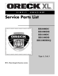
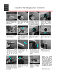
1
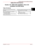
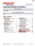
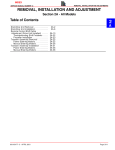
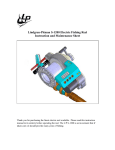
INDEX
GASOLINE STERNDRIVE INSTALLATION MANUAL
Shift Cable Installation
Alpha Models - Drive Unit Not Installed
We recommend the use of a Quicksilver remote control and cable. Refer to Mercury
Precision Parts / Quicksilver Accessories Guide for selection. However, if a control other
than Quicksilver is to be used, control must provide a shift cable travel (at the shift plate end)
of 2-7/8 in. (73 mm) to 3-1/8 in. (80 mm) with a 15-20 lb. (6.8-9 kg) load applied to the cable
end guide.
NOTE: On engines with Alpha drives, the measurement indicated above can be taken by
installing the remote control shift cable and using the shift assist assembly (provided) to
place the proper load on the shift cable.
1. Place a mark on the tube against the edge of the cable end guide.
d
e
aa
b
c
a
a
b
c
d
e
90-860172011
50368
- Shift Assist Assembly
- Remote Control Shift Cable - In FORWARD Gear Position
- Edge Of Cable End Guide
- Remote Control Shift Cable - In REVERSE Gear Position
- Measurement Taken From Mark To Edge Of Cable End Guide:
2-7/8 in. (73 mm) to 3-1/8 in. (80 mm)
Page 67 of 137
INDEX
GASOLINE STERNDRIVE INSTALLATION MANUAL
IMPORTANT: If boat is being equipped with a REMOTE CONTROL THAT HAS
SEPARATE SHIFT AND THROTTLE LEVERS, the shift assist assembly that is shipped
with the engine should NOT be used. The use of the shift assist assembly with this
type of remote control can cause the shift lever to move out of gear unexpectedly.
The following kit will have to be ordered to connect remote control shift cable when shift
assist assembly is not used.
Spacer Kit
23-11284A1
d
a
b
c
a
b
c
d
50310
- Clevis Pin
- Washer
- Spacer
- Cotter Pin
NOTE: Do not discard shift assist assembly until after it is used in step 3., following.
IMPORTANT: Shift cable must be connected at the remote control for the appropriate
rotation (LH or RH) drive unit, as explained following:
RIGHT HAND ROTATION - Control cable will have to be installed in remote control so that
cable end will move in direction “A” when shift handle is placed in the FORWARD position.
LEFT HAND ROTATION - Control cable will have to be installed in remote control so that
cable end will move in direction “B” when shift handle is placed in the FORWARD position.
A
B
71656
Page 68 of 137
90-860172011
INDEX
GASOLINE STERNDRIVE INSTALLATION MANUAL
IMPORTANT: Use the following procedure to temporarily install shift cables if boat
will be shipped without drive unit installed. Refer to Shift Cable Installation for shift
cable adjustment procedure once drive unit is installed.
1. Remove shift cable attaching hardware.
c
a
b
50308
a - Cotter Pin
b - Clevis Pin And Cotter Pin
c - Washer And Locknut
2. Place remote control shift lever in NEUTRAL position.
3. Temporarily install clevis pin through remote control shift cable end guide, shift assist
assembly end and into hole in shift lever. Then adjust brass barrel so that hole in barrel
aligns with anchor stud.
c
e
d
a
a
b
c
d
e
90-860172011
b
50308
- Clevis Pin
- Shift Cable End Guide
- Shift Assist Assembly End
- Shift Lever
- Brass Barrel (On Stud)
Page 69 of 137
INDEX
GASOLINE STERNDRIVE INSTALLATION MANUAL
4. Remove remote control shift cable and shift assist assembly.
IMPORTANT: Install the cotter pin through the top of the barrel retainer.
5. Install drive unit shift cable as shown. Secure brass barrel in barrel retainer with cotter
pin and spread both prongs. Secure cable end guide with washers (one on each side
of end guide) and locknut. Tighten locknut until it contacts, then loosen 1/2 turn.
b
a
75415
Without Shift Assist Assembly
a - Cotter Pin
b - Locknut And Washers
Page 70 of 137
90-860172011
INDEX
GASOLINE STERNDRIVE INSTALLATION MANUAL
6. Install remote control shift cable (with or without shift assist assembly as applicable) and
secure with hardware as shown. Tighten locknut finger tight only and do not spread
cotter pin completely. (Remote control shift cable fasteners will have to be removed
again to properly adjust shift cables under Shift Cable Installation section of this
manual.)
d
a
e
b
c
50308
With Shift Assist Assembly
a - Remote Control Shift Cable
b - Shift Assist Assembly
c - Clevis Pin And Cotter Pin
d - Large I.D. Washer
e - Small I.D. Washer And Locknut
c
a
d
b
e
g
h
i
f
50310
Without Shift Assist Assembly
a - Remote Control Shift Cable
b - Pin
c - Cotter Pin (Existing)
d - Spring (Existing)
e - Washer (Existing)
f - Washer
g - Spacer
h - Washer (Existing)
i - Locknut (Existing)
90-860172011
Page 71 of 137
INDEX
GASOLINE STERNDRIVE INSTALLATION MANUAL
Shift Cable Installation
Alpha Models - Drive Unit Installed
IMPORTANT: Shift cable adjustment for a right hand (RH) rotation drive unit is
different than the procedure for adjusting a left hand (LH) rotation drive unit. Be sure
to refer to the appropriate procedure when performing the following steps.
IMPORTANT: Drive unit must be installed.
IMPORTANT: DO NOT run engine.
1. Remove remote control shift cable and shift assist assembly (if installed).
b
b
a
75414
50310
With Shift Assist Assembly Without Shift Assist Assembly
a - Shift Assist Assembly
b - Remote Control Shift Cable
2. Ensure shift lever adjustable stud is at bottom of slot.
a
50309
a - Adjustable Stud
90-860172011
Page 89 of 137
INDEX
GASOLINE STERNDRIVE INSTALLATION MANUAL
3. Shift remote control as stated in a. or b. following:
a. Right Hand (RH) Rotation Drive Unit - FORWARD gear, past detent, into WOT
position.
b. Left Hand (LH) Rotation Drive Unit - REVERSE gear, past detent, into WOT
position.
F
N
R
(RH)
R
(LH)
4. Place drive unit into gear by pushing in on drive unit shift cable while simultaneously
rotating propeller shaft COUNTERCLOCKWISE until shaft stops. This will ensure full
clutch engagement. Maintain a light pressure on the drive unit shift cable to hold it at
the end of its travel (this removes all slack from the cable).
IMPORTANT: Do not use excessive force when holding pressure on the drive unit
shift cable. Excessive force would be indicated by movement of the shift cutout
switch.
a
22266
a - Propeller Shaft - Rotate COUNTERCLOCKWISE
Page 90 of 137
90-860172011
INDEX
GASOLINE STERNDRIVE INSTALLATION MANUAL
5. Lightly pull on remote control shift cable end guide (to remove slack from remote control
and cable) and adjust brass barrel as necessary to align attaching points with shift lever
clevis pin hole and stud. Be sure to maintain light pressure on drive unit shift cable.
c
d
a
b
50309
a
b
c
d
- End Guide
- Brass Barrel
- Shift Lever Clevis Pin Hole
- Stud
6. Temporarily install remote control shift cable on stud and install clevis pin.
a
b
50308
a - Remote Control Shift Cable
b - Clevis Pin
7. Shift remote control as stated in a. or b. following:
a. Right Hand (RH) Rotation Drive Unit - REVERSE gear, past detent, into WOT
position.
b. Left Hand (LH) Rotation Drive Unit - FORWARD gear, past detent, into WOT
position.
(LH)
(RH)
R
90-860172011
F
N
R
Page 91 of 137
INDEX
GASOLINE STERNDRIVE INSTALLATION MANUAL
8. To ensure full clutch engagement, simultaneously rotate propeller shaft CLOCKWISE
until shaft stops.
a
22267
a - Propeller Shaft - Rotate CLOCKWISE
9. Check shift cutout switch plunger position. Pin must be centered.
a
75435
a - Shift Cutout Switch Plunger Pin
10. If plunger pin is not centered:
a. Ensure adjustable stud is at bottom of slot in shift lever.
b. Check remote control for proper shift cable output [3 in. (76 mm) ± 1/8 in. (3 mm)].
c. If a. and b. are correct, ensure drive unit shift cable is not crushed or kinked. (If drive
unit shift cable is binding, the shift cutout switch plunger pin will move off center
when shifting into and out of FORWARD and REVERSE.)
NOTE: If shift cable was damaged during installation, install new shift cable assembly in
accordance with instructions contained in sterndrive service manual, then repeat shift cable
adjustment procedure.
Page 92 of 137
90-860172011
INDEX
GASOLINE STERNDRIVE INSTALLATION MANUAL
11. After remote control shift cable has been properly adjusted, reinstall cable and shift
assist assembly (if applicable) and secure with hardware as shown. If shift assist
assembly attaching points will not align, push in or pull out on end of shift assist
assembly to install. Do not attempt to readjust shift cable.
d
d
a
e
a
h
g
b
c
i
f
j
c
i
50308
g
i
50310
With Shift Assist Assembly
Without Shift Assist Assembly
a - Remote Control Shift Cable
b - Shift Assist Assembly
c - Clevis Pin
d - Cotter Pin (Spread Both Prongs)
e - Large I.D. Washer
f - Small I.D. Washer
g - Locknut (Tighten Until Contacts, Then Loosen 1/2 Turn)
h - Spring (Existing)
i - Washer (Existing)
j - Spacer
90-860172011
Page 93 of 137
INDEX
GASOLINE STERNDRIVE INSTALLATION MANUAL
IMPORTANT: If an extra long remote control shift cable is used, there are a large
number of bends in remote control shift cable or remote control has inadequate
output travel, an additional adjustment may be necessary. Refer to step 12. or 13. as
applicable.
12. Remote Control with Single Lever Shift/Throttle Control:
a. RIGHT HAND (RH) propeller rotation drive unit - Shift remote control into
REVERSE gear, WOT position while simultaneously rotating propeller shaft
CLOCKWISE. Clutch should engage and cause propeller shaft to lock. If clutch does
not engage, loosen adjustable stud on shift lever and move it up in slot until clutch
engages with REVERSE gear. Retighten stud. Shift remote control several times
and stop in REVERSE to recheck shift cutout switch position. Pin must be centered.
b. LEFT HAND (LH) propeller rotation drive unit - Shift remote control into
FORWARD gear, WOT position while simultaneously rotating propeller shaft
CLOCKWISE. Clutch should engage and cause propeller shaft to lock. If clutch does
not engage, loosen adjustable stud on shift lever and move it up in slot until clutch
engages with FORWARD gear. Retighten stud. Shift remote control several times
and stop in FORWARD to recheck shift cutout switch position. Pin must be centered.
13. Two Lever Remote Control with Separate Shift and Throttle Levers:
a. RIGHT HAND (RH) propeller rotation drive unit - While turning propeller shaft
CLOCKWISE, move remote control shift handle into full REVERSE position. Clutch
should engage before shift lever comes to a stop. If clutch does not engage, loosen
adjustable stud on shift lever and move it up in slot until clutch engages with
REVERSE gear. Retighten stud. Shift remote control several times and stop in
REVERSE to recheck shift cutout switch position. Pin must be centered.
b. LEFT HAND (LH) propeller rotation drive unit - While turning propeller shaft
CLOCKWISE, move remote control shift handle into full FORWARD position. Clutch
should engage before shift lever comes to a stop. If clutch does not engage, loosen
adjustable stud on shift lever and move it up in slot until clutch engages with
FORWARD gear. Retighten stud. Shift remote control several times and stop in
FORWARD to recheck shift cutout switch position. Pin must be centered.
b
a
50309
75435
a - Adjustable Stud
b - Shift Cutout Switch Plunger Pin
Page 94 of 137
90-860172011
INDEX
GASOLINE STERNDRIVE INSTALLATION MANUAL
Troubleshooting Shift Problems
NOTE: The following information is provided to assist an installer in troubleshooting if hard
shifting or chucking/racheting is encountered when shifting into FORWARD gear.
1. When installing the control box in the side panel of the boat, make sure that the cables
have enough clearance to operate. This is necessary because the cables move up and
down when the shift handle is moved. If the control box is mounted too far back toward
any fiberglass structure, the cables will be interfered with; this will cause very hard
shifting.
NOTE: The control box housing can be rotated in 30 degree increments to improve cable
routing.
74688
Proper Cable Bend
74689
Improper Cable Bend
2. Make sure that when the shift cable from the control box is led through the side gunnel
of the hull, it does not have any extremely sharp bends in it as this will cause stiff shifting.
90-860172011
Page 95 of 137
INDEX
GASOLINE STERNDRIVE INSTALLATION MANUAL
3. Before installing the shift cable into the control box, extend the stainless rod eye end of
the cable and grease it with 2-4-C Marine Lubricant with Teflon. Move it back and forth
to allow even distribution of the grease.
22005
Description
2-4-C Marine Lubricant With
Teflon
Where Used
Part Number
Shift Cable End
92-825407A3
4. Do not strap or clamp the control cables to any other cables or rigid structure within
3 ft. (914 mm) of the control box.
5. Be sure the cable is not permanently kinked.
6. Make sure there is proper clearance for cable movement when the control box is
installed in the side panel. The cables must have room to move up and down when the
control handle is shifted into either FORWARD or REVERSE.
7. Ensure that the engine was not set down on the intermediate shift cable during
installation, as this will crush the inner cable tubing and cause improper and / or stiff
shifting.
8. DO NOT fasten the shift cable with straps or clamps to any other cable within 5 ft.
(1.5 m) of the shift plate.
9. DO NOT fasten the shift cable to the transom with any type of plastic clips or fasteners
within 5 ft. (1.5 m) of the shift plate.
10. DO NOT overtighten the throttle or shift cable attaching nuts at the engine end. Barrel
and cable end must be free to rotate on the mounting stud.
NOTE: Lubricate attaching points with engine oil.
Description
SAE 30W Engine Oil
Page 96 of 137
Where Used
Part Number
Shift Cable Pivot Points
Obtain Locally
90-860172011
INDEX
GASOLINE STERNDRIVE INSTALLATION MANUAL
11. Check the intermediate shift cable routing from the transom assembly to the shift plate
as follows:
a. The cable should come through the transom, above the exhaust pipe and make a
turn toward the starboard side of the boat between the exhaust pipe and the engine
flywheel housing.
b. The cable should then be routed under the starboard rear engine mount and turn
toward the transom.
c. The cable should then go up behind the power steering valve and loop over to the
shift plate on the engine, where it is connected to the anchor points on the shift plate.
Following this routing will prevent the engine coupler from damaging the cable.
74901
74903
3.0L Model
V6 and V8 Models
NOTE: A final check of the adjustments should be made with the boat in the water and
engine running. If this cannot be done or is not done at your manufacturing facility,
arrangement should be made with the dealer to do this as part of the pre-delivery inspection.
90-860172011
Page 97 of 137
INDEX
GASOLINE STERNDRIVE INSTALLATION MANUAL
Predelivery Preparation
Once the power package installation is complete, the following final steps should be taken
to prepare power package for delivery to the customer. It is the boat manufacturer’s
responsibility to perform these procedures, or to make arrangement with the dealer to have
these procedures completed.
Power Steering Fluid
IMPORTANT: Use only specified lubricant.
CAUTION
DO NOT RUN POWER STEERING DRY or pump will be damaged.
1. Position sterndrive unit so that it is straight back.
2. Remove fill cap from power steering pump and check fluid level using dipstick. Add
fluid as required.
NOTE: Be prepared to add fluid to pump when first starting engine.
a
a
b
71672
76859
a - Fill Cap
b - Dipstick
Description
Where Used
Power Trim and Steering Fluid
Dexron III - Automatic
Transmission Fluid
Page 98 of 137
Part Number
92-90100A12
Power Steering Pump
Obtain Locally
90-860172011