1
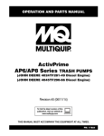
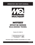
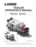
Quality is not expensive, It’s Priceless
Owners
Manual
Northland Products, Inc.
2608 Spitfire Lane, Prescott, AZ 86301
928.636.9298 Toll Free 866.235.0038 Fax 928.636.1070
www.northlandproductsinc.com
Table of Contents
Introduction
1
Before Using
2
Operation
3.1 Filling Your Waterboy
3.2 Dispensing Water
3.3 Storage
3.4 Electric Brakes
3
Parts Lists
4
4.1 Axle
4.2 Axle, Electric
4.3 Frame
4.4 Hitch
4.5 Tank
4.6 Pump
4.7 Electric Brake
Hitch
4.8 Pump Manifold
Specifications
5
Accessories
6
Introduction
1
Congratulations on your purchase of a
Northland Products, Waterboy Transporter. Your
Waterboy can provide years of reliable service
with only minor care and maintenance.
Waterboy Transporters are covered by a limited
1 year warranty. These units are not intended
for transporting potable water
When calling with any questions about your
Waterboy, or when purchasing accessories,
please have your VIN number available. This is
located on the tag attached to the left of the
center front frame rail.
Fig. 1
VIN Number
Fig. 2
Your Waterboy VIN#_________________
Before Using Your Waterboy
We recommend that the following items be checked before using
your Waterboy Transporter
1. Brake actuator fluid level(Hydraulic brake units only). Remove the master cylinder cap and fill
the reservoir to 3/4 full with DOT-3 or DOT-4 brake fluid. Fig. 3. Consult the Titan service manual
for further information.
2. For electric brake system questions, see the “THE ENGAGER” service instructions in section 6
of the manual.
3. Tire pressure. ST205/75D15 tire pressure cold is 50 PSI. Always check tires for cracking due to
environmental exposure. Consult a tire professional if you have any questions.
4. Pump engine oil should be checked before each use. Use 4-stroke automotive detergent oil of
API service class SE or higher grade. For further information consult the manufacturers service
manual for your specific engine (Robin, Honda, etc.).
5. Proper operation of lights. Repair or replace damaged or worn out components as required.
6. Check pump engine fuel level. Use only 87 octane (unleaded) or better.
7. Check that all hoses are securely fastened and connections tight. Close hatch while traveling.
8. Rotate the tongue jack to the travel position once the hitch has been attached to the tow
vehicle.
9. For pump information consult the supplied Grainger or Multiquip manual.
9. Do not allow children to play on, around, or in your Waterboy.
10. Limit speed while transporting to 45 mph.
Fig. 3
2
Operation
3.1 Filling your Waterboy
Your Waterboy can be filled by connecting to a pressurized water supply, drafting
from a pond or other static water source, or by simply pouring through the manhole.
Fig. 4 shows the standard hose configuration.
Pump Prime Hole
3
Pump Outlet
Pump Inlet
Fig. 4
3.1.1 Drafting from a static water supply
1. Disconnect the pump outlet hose. Fig. 5
Fig. 5
2. Disconnect the pump inlet hose and attach to
the pump outlet. Fig. 6
3. Attach the suction hose to the pump inlet. Be
sure other end is under the surface of the water
source. Fig. 7
Fig. 6
Fig. 7
3.1.1 Drafting from a static water supply. Cont’
4. Before attempting to start pump engine, remove the cap from the pump priming hole
and fill the pump housing with water. Reinstall cap and be sure it is tight before starting
engine. Fig. 1
5. Open tank valve by turning counterclockwise so it aligns with the transporter body.
6. Start pump engine. There will be a several minute wait while the pump self-primes.
Water level can be observed through the tank material. Turn off engine when tank is
full. When finished filling, turn tank valve 1/4 turn clockwise, Fig. 8. This will provide
app. 550 gallons.
Open
Front of
Transporter
Closed
Fig. 8
3.1.2 Connecting to a pressurized water supply.
1. Connecting and filling the tank from a pressurized
supply does not require use of the pump and engine.
Safety strap
2. Locate the fill connection on the right rear of the tank
and attach the fill hose. Fig. 9
3. This connection is designed to break away if the
transporter is driven away with the hose still connected.
Be sure safety strap is connected.
Pressurized Fill Connector
Fig. 9
Manhole cover
4. Remove manhole cover and start source pump or
open source valve. Fig. 10
5. Be sure to close source valve or turn off pump, then
disconnect rear tank connection and reinstall manhole
cover before moving transporter
Fig. 10
Pressure
Fill
Nozzle
3
3.2 Dispensing Water
Your Waterboy Transporter has 3 ways to dispense water.
1. Side Sprayer
2. Rear Sprayer
3. Hose connection
3
3.2.1 Side Sprayer
1. Be sure tank drain, plumbing drain, rear sprayer, and hose valves are closed.
Side Sprayer Valve
Side Sprayer
Pressure Relief
Valve
Tank Drain
Garden Hose
Connection
Rear Sprayer Valve
Plumbing Drain
Fig. 11
(Shown with engine removed for clarity)
2. Start engine.
3. Stand away from the end of the side sprayer nozzle and open side sprayer valve.
Fig 11
4. Close the valve and turn off the engine when done.
3.2.2 Rear Sprayer
1. Be sure tank drain, plumbing drain, side sprayer, and hose valves are closed.
2. Start engine.
3.2.2 Rear Sprayer cont’
3. Be sure rear transporter area is clear and open rear sprayer valve, Fig. 11.
Nozzles can be rotated to direct spray.
4. When done close valve and turn off engine.
3.2.3 Garden Hose Connection
1. Make sure all other valves are closed.
2. Connect hose tightly to garden hose connection.
3. Start engine.
4. Open garden hose connection.
5. When done close valve, turn off engine, and store garden hose.
3.2.4 Transfer Connection
1. Your Waterboy engine/pump can be used to transfer water from one
location to another. Simply disconnect the transporter plumbing hose from
the pump outlet and connect a longer discharge hose.
2. Prime pump and start engine as directed previously.
3. When done, turn off engine, remove discharge hose, and reconnect
transporter plumbing.
3.3 Storage
Your Waterboy can be stored safely with water in the tank, even in cold weather.
Simply open the plumbing drain to remove water in the plumbing system. Be sure
to close valve before the next use. Fig. 8
Be sure to lock access cover lid to discourage children from trying to enter the
Waterboy.
Cover your tires to protect from sun exposure. Tires can deteriorate even when not
being used, causing an unsafe condition.
3
3.4 Electric Brakes
3
3.4 Electric Brakes Cont’
3
4.1 Parts List
Axle Assembly
Hydraulic
Item No.
Part Number
Qty
1
WB2-181
8
Shackle Link
2
WB2-187
4
ST205/75R15 Tire, Rim
3
WB2-172H
1
Brake Line Assembly
4
WB2-182
2
Equalizer
5
WB2-176H
4
Backing Plate
6
WB2-186H
4
U Bolt Plate
7
WB2-178H
4
Leaf Spring
8
WB2-180
14
Shackle Bolt
9
WB2-179
14
Shackle Nut
10
WB2-185H
8
U Bolt 1/2 x 5.5
11
WB2-174H
2
Axle
12
WB2-675
20
Lug Nut
13
WB2-175H
4
Brake Drum
14
WB2-684
2
Screw : Hex-Flange - 0.25 x 1.0
Caution:
Tire pressure must be maintained at 50 PSI(cold).
Description
3
14
11
2
A
5
6
7
10
5
9
1
4
12
13
8
4
4.2 Parts List
Axle Assembly
Electric
Item No.
Part Number
Qty
Description
1
WB2-181
8
Shackle Link
2
WB2-187
4
ST205/75D15
3
WB2-182
2
Equalizer
4
WB2-176E
4
Back Plate
5
WB2-186E
4
U Bolt Plate
6
WB2-178E
4
Leaf Spring
7
WB2-180
14
Shackle Bolt
8
WB2-179
14
Shackle Locknut
9
WB2-185E
8
U Bolt 1/2 x 5.5
10
WB2-174E
2
Axle
11
WB2-675
20
Lug Nut
12
WB2-175E
4
Brake Drum
10
2
4
A
4
5
6
9
4
8
Caution:
Tire pressure must be
maintained at 50 psi
1
3
11
12
7
4.3 Parts List
Frame Assembly
Item No.
Part Number
Qty
Description
1
WB2-601
16
Clip
2
WB2-600
1
Frame
3
WB2-602
2
Baffle Storage Pan
4
WB2-607
1
Right Pan
5
WB2-603
1
Left Pan
6
WB2-604
1
Tank Hold Down Strap
7
WB2-605
2
Pump Mounting Bracket
8
WB2-199
2
5/8 Insert Lock Nut
9
WB2-608
2
5/8 Washer
10
WB2-609
4
Marker Grommet
11
WB2-610
2
Amber Marker Light
12
WB2-611
2
RED Marker Light
13
WB2-612
2
Tail Light Grommet
14
WB2-613
2
Tail Light
15
WB2-133
4
3/8 x 1.25 HH G5 Galv.
16
WB2-134
4
3/8 Insert Lock Nut
17
WB2-606
2
Anchor Bolt
18
WB2-678H
1
Hydraulic Brake Harness
19
WB2-678E
1
Electric Brake Harness
20
WB2-234
2
6-Pin Connector
21
WB2-685
4
Pigtail
21
6
4
14
7
13
10
1
12
17
3
5
2
15
9
16
8
20
18
19
11
4
4.4 Parts List
Hitch Assembly
Item No.
Part Number
Qty
Description
1
WB2-173
1
7,500 lb. Actuator
2
WB2-208
1
2,000 lb. Tongue Jack
3
WB2-189
1
Hammerblow Hitch 2" Ball
4
WB2-198
2
5/8 x 4.5 HH G5 Galv.
5
WB2-199
2
5/8 Insert Lock Nut
6
WB2-190
6
1/2 x 1.5 HH G5 Galv.
7
WB2-233
6
1/2 Insert Lock Nut
8
WB2-192
6
1/2 Washer
9
WB2-197
2
3/8 Cold Shut
10
WB2-196
2
5/16 Safety Chain
2
4
8
1
7
5
6
9
3
10
4
4.5 Parts List
Tank Parts
Item No.
Part Number
Qty
Description
1
WB2-614
1
Water Tank
2
WB2-148
1
16in Manway Cover
3
WB2-615
2
Hose Wrap
4
WB2-618
2
1 x .75 Plastic Bushing
5
WB2-619
2
Rear Spray Nozzle
6
WB2-620
2
Lockline Male Adapter
7
WB2-621
2
1" Sprayer Hose
8
WB2-622
1
1" Sprayer Supply Hose
9
WB2-623
1
Fill Adapter
10
WB2-624
1
Fill Spout
11
WB2-625
6
1.5in Clamp
12
WB2-626
2
2.5in Clamp
13
WB2-627
1
Baffle Strap
14
WB2-628
1
Buckle
15
WB2-629
2
Break Away Coupling Clamp
16
WB2-631
1
Handle, Internal Valve
17
WB2-632
2
Flexy Flare
18
WB2-633
1
Valve Shaft Seal
19
WB2-118
1
2in Close Nipple
20
WB2-120
1
2" Valve
21
WB2-230
1
2in Close Nipple PVC
22
WB2-113
1
Suction Strainer
23
WB2-634
1
Internal Valve Rod
24
WB2-635
1
1in Barb Tee PVC
25
WB2-686
1
1" Barb x 1" MPT PVC
26
WB2-636
2
Baffle Plate
27
WB2-637
1
Break Away Coupling
28
WB2-146
1
2in MxM Cam Lock
29
WB2-638
2
Fill Pipe Gasket
30
WB2-639
2
Fill Pipe Nut
31
WB2-640
1
2in Hydrant Hose
32
WB2-641
2
1in Barb x 1in MPT 90
33
WB2-642
2
3/8 - 16 Nut
34
WB2-643
1
3/8 - 24 Jamb Nut SS
35
WB2-644
2
3/8 - 16 x 2.5 HH CS SS
36
WB2-645
6
3/8 - 16 Insert Lock Nut SS
37
WB2-157
2
3/8 Washer
38
WB2-648
6
3/8 Sealing Washer SS
39
WB2-117
1
2in Bulk Head
40
WB2-647
1
Service Valve Bracket
41
WB2-649
4
3/8 - 16 x 1.5 HH CS SS
42
WB2-679
1
.25 Rope
4
4.5 Parts List
Tank Parts Cont’
27
3
2
10
15
42
37
30
38
12
36
41
38
35
31
40
33
4
16
28
18
29
11
23
34
22
19
9
7
25
24
39
8
32
20
4
13
17
21
6
26
14
5
4.6 Parts List
Pump Assembly
Description
Item No.
Part Number
Qty
1
WB2-227
1
Robin Pump Assembly
2
WB2-153
1
Honda Pump Assembly
3
WB2-152
1
Honda HP Pump Assembly
4
WB2-652
2
2in M Cam x 2in FPT
5
WB2-244
4
3/8 x 2 HH G5 EG
6
WB2-134
4
3/8 Insert Lock Nut
7
WB2-157
4
3/8 Flat Washer
8
WB2-243
4
Rubber Pump Mount
1
1
1
7
6
4
8
5
4
4.7 Parts List
Electric Brake
Hitch Assembly
Item No.
Part Number
Qty
Description
1
WB2-666
1
Hitch mount
2
WB2-667
1
Break away battery
3
WB2-668
1
Break away switch
4
WB2-669
1
3 in pintle ring
5
WB2-670
1
Harness clamp
6
WB2-671
3
Screw : Pan - 0.25 x 1.0
7
WB2-674
1
Bolt : Hex - 0.25 x 1.0
8
WB2-672
4
1/4-20 insert lock nut
9
WB2-673
4
1/4 galv. washer
10
WB2-190
6
1/2 x 1.5 HH G5 Galv.
11
WB2-233
6
1/2 Insert Lock Nut
12
WB2-192
6
1/2 washer
13
WB2-199
2
5/8 Insert Lock Nut
14
WB2-198
2
5/8 x 4.5 HH G5 Galv.
1
2
4
14
13
8
9
6
10
12
11
7
3
5
8
4
4.8 Parts List
Pump Manifold
Assembly
Item No.
Part Number
Qty
1
WB2-653
1
1in Cross
2
WB2-130
2
1in Close Nipple
3
WB2-136
1
1in Street Ell
4
WB2-128
1
1/2 MPT Hose Bib
5
WB2-131
2
1in MPT x 1in Barb
6
WB2-654
1
Rear Sprayer Hose
7
WB2-655
1
2 x 1 Bushing
8
WB2-123
2
2 x 1.5 Bushing
9
WB2-656
2
1 x 1/2 Bushing
10
WB2-657
1
1 x 3/4 Bushing
11
WB2-124
2
2in Barb x 2in MPT
12
WB2-118
1
2in Close Nipple
13
WB2-658
1
Dump Valve
14
WB2-663
1
Dump Valve 45
15
WB2-239
2
1.5in Hose Clamp
WB2-659
1
2in Suction Hose
17
WB2-660
1
2in Discharge Hose
18
WB2-174
4
P11 Punch Lok Clamp
19
WB2-661
1
2 x 1.5 Bell
20
WB2-105
1
Side Spray Nozzle
WB2-125
2
2in Tee
22
WB2-225
2
5/16 x 2.5in U-Bolt
23
WB2-171
4
5/16 Insert Lock Nut
24
WB2-662
1
75 PSI Pressure Relief
25
WB2-129
1
1in BB Valve
26
WB2-121
1
1.5in BB Valve
27
WB2-664
2
2in F Cam x 2in Barb
28
WB2-665
2
1.5 x 2.5 Nipple
29
WB2-680
1
125 PSI Pressure Relief
30
WB2-676
1
Drain Cock
16
21
Description
4
4.8 Parts List
Pump Manifold
Assembly Cont’
29
9
18
23
26
21
17
28
22
27
28
19
20
7
2
8
4
24
12
9
5
16
11
10
8
6
13
1
14
15
3
30
25
4
Specifications
Capacity..........550 Gallons
GVWR............6000 lbs with 2” Ball
7000 lbs with 2 5/16” Ball
Weight............1325 lbs (empty)
Dims...............L - 13’2”, W- 80”, H- 53 1/4”
Axles..............Dexter Tandem 3500 lb Each
Brakes............4 Wheel Hydraulic Surge
Wheels...........Steel Spoke 5”on 4 ½” Centers
Tires................Biased ST205/75D15
Suspension.....Dual Leaf Spring
Frame..............5” (Galvanized) Channel Roll
Form 3” x 4” Welded Tongue
Hitch...............Standard 2”, Optional 2 5/16”
Or Pintle
Tank................Polyethylene 3/8” Thick, 16”
5
Removable Manhole Cover
Repairable
Accessories
High Pressure Pump
Model # QP-205SH Honda GX-160
- 5.5 hp with Oil Alarm
- Multiquip Centrifugal Pump
- 2” Suction with 1 ½” Discharge
- 106 psi @ 106 g.p.m.
Hose Kit
- (1) 2” x 20’ Suction Hose w/Strainer
- (1) 1 ½” x 50’ Discharge Hose w/Fittings
- (1) Fog Nozzle w/ 1 ½” FPT
6