1
Multi Electric Mfg., Inc. IB LTDZ_US Page 12 of 33 2.2
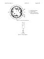
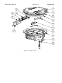
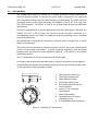
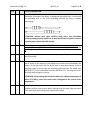
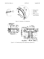
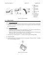
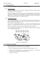
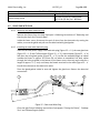
SHALLOW BASE The shallow base (Figure 8) consists of a treated aluminium casting containing an electrical feed‐thru system to connect the power cables, consisting of one cable lead with receptacle coming inside the base through one cable gland. The cable lead with receptacle consists of two single‐pole leads, size 14AWG (2.5 mm2), 40” (1 m long), with FAA L‐823 receptacle. The letters "A" and “B” are printed inside the base for cable leads identification. The base is equipped with an internal grounding screw with yellow‐green cable lead, size 14AWG (2.5 mm2, 0.250 m long), with female terminal for quick connection to a corresponding lead on the fixture. An additional external grounding screw is provided close to the cable entry. The shallow base is designed for cementing in place by means of epoxy‐resin in a hole drilled in the pavement. The fixture has to be fastened to the base by means of six hex cap screws, complete with external silicon‐coated lock‐washer. A gasket (supplied separately) must be placed between base and fixture for water tightness (Figure 8 ‐ n°9) placed in the relevant shallow base groove. The 12” shallow base is 320 mm in diameter and 150 mm high. On request, special bases provided with holes for conduit connections can be supplied. Inside the base two holders are provided to properly restrain the secondary power cable, in case the cable is coming through a conduit. 1. 2. 3. 4. 5. 6. 7. 8. 9. Cable gland for cable entry External grounding screw Cable leads with socket Internal grounding screw Grounding cable with female faston terminal Letters “A” for cable lead identification Power cable holders Threaded inserts for fixture fastening by bolts O‐Ring between fixture and base
Figure 8 – Standard 12” shallow base