1
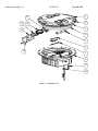
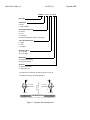
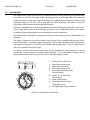
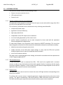
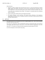
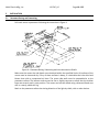
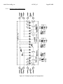
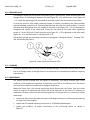
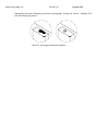
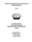
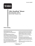
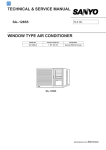
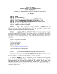
INSTRUCTION MANUAL FOR USE, INSTALLATION AND MAINTENANCE LTHE LED INSET RUNWAY THRESHOLD/ END LIGHT L850 (L) D Manufactured By: Multi Electric Mfg., Inc. 4223 W Lake Street Chicago, IL 60624 www.multielectric.com Multi Electric Mfg., Inc. IB LTHE_US Page 2 of 35 LIMITED PRODUCT WARRANTY THE FOLLOWING WARRANTY IS EXCLUSIVE AND IN LIEU OF ALL OTHER WARRANTIES, EXPRESSED, IMPLIED, OR STATUTORY, INCLUDING, BUT NOT BY WAY OF LIMITATION, ANY WARRANTY OF MERCHANTABILITY OR FITNESS OF PURPOSE. Multi Electric Mfg., Inc. (the company) warrants the LED based products manufactured by the company, to be free of defects in materials and workmanship, for a period of (5) year from the date of installation. The company’s sole liability is limited to either repair or replacement of the defective material at the manufacturer’s sole discretion. The manufacture reserves the right to inspect or test at its facility, any products claimed to be defective during normal business hours. The Purchaser making claims against this warranty are responsible for the full costs associated with removal and replacement of defective materials, transportation of all materials along with all other permits, fees and costs associated with the disruption of serve, restoration, replacement or repair of the product and facilities. Materials and Products not manufactured by Multi Electric, Mfg., Inc. but supplied under the same contract or purchase order carry the original equipment manufacturers warranty. Failures caused by improper handling, storage and transportation, Acts of God, Civil and Political conflict, accident, incursion with moving vehicles, tampering, or unauthorized modification are specifically excluded from coverage under this warranty agreement. Multi Electric Mfg., Inc. IB LTHE_US Page 3 of 35 IMPORTANT: READ THIS DOCUMENT Before proceeding to the operations of installation, commissioning, operation, maintenance or disposal, carefully read the entire document. SAFETY INFORMATION Extreme caution should be exercised when working with this equipment; it is normally used or connected to circuits that operate at dangerous voltages and can be fatal. The following section contains important safety information that you must follow when installing and using the apparatus. Misuse of the equipment or lack of care in applying safety procedures and prescriptions specified in this document, may result in a hazard. Avoid contact with voltage or current sources. Do not remove protections and the safety devices for any reason. MAINTENENCE ON THE EQUIPMENT ‐ SKILLS Maintenance on the equipment and access to its internal parts shall be done by qualified personnel, adequately trained and aware of the risks related to electricity and high voltages. Safety rules shall be adopted when working on the equipment, or on cables and other apparatus connected to the it WHEN HANDLING AND SERVICING THIS EQUIPMENT, OBSERVE PRECAUTIONS FOR HIGH VOLTAGE EQUIPMENT. Before any access, inspection or intervention, be sure to have switched‐off the unit, opened the main circuit breaker and removed the supply to the unit (by opening the circuit breaker/switch on the distribution board at the beginning of the supply line). Then wait discharge time (at least 5 minutes), ground carefully the system, and check for voltage presence before accessing. Multi Electric Mfg., Inc. IB LTHE_US Page 4 of 35 Table of Contents 1 GENERAL .............................................................................................................................................................................. 6 2 MAIN FEATURES ................................................................................................................................................................... 6 2.1 REMOVABLE LIGHT UNIT ...................................................................................................................................................... 6 2.1.1 Dome ................................................................................................................................................................................... 6 2.1.1 Optical Assembly .................................................................................................................................................................. 7 2.1.2 Power Supply/Control Board ................................................................................................................................................ 7 2.1.3 Lower Cover ......................................................................................................................................................................... 7 2.2 SHALLOW BASE .................................................................................................................................................................. 13 2.3 ELECTRONIC SECTION ......................................................................................................................................................... 14 2.3.1 Current / current conversion circuit (patented) ................................................................................................................... 14 2.3.2 LED command circuit .......................................................................................................................................................... 14 2.3.3 Control circuit..................................................................................................................................................................... 14 2.4 ARCTIC KIT .......................................................................................................................................................................... 15 3 INSTALLATION .................................................................................................................................................................... 16 3.1 Pavement Boring and Sawcutting ....................................................................................................................................... 16 3.1.1 Scheme of Light Configurations ........................................................................................................................................... 17 3.2 INSTALLING THE SHALLOW BASE ........................................................................................................................................ 18 3.3 INSTALLING THE LIGHT UNIT ON L‐868 BASE ....................................................................................................................... 22 3.4 SECONDARY WIRING .......................................................................................................................................................... 22 4 MAINTENANCE ................................................................................................................................................................... 23 4.1 MAINTENANCE PROGRAM .................................................................................................................................................. 23 4.1.1 Periodical Checks ................................................................................................................................................................ 23 4.1.2 Snowplow Operations ........................................................................................................................................................ 24 4.2 REMOVING AND OPENING THE LIGHT UNIT FROM THE BASE .............................................................................................. 24 4.2.1 Removing the fixture .......................................................................................................................................................... 24 4.2.2 Opening the fixture ............................................................................................................................................................ 24 4.2.3 Closing the fixture .............................................................................................................................................................. 24 4.2.1 Leakage test ....................................................................................................................................................................... 25 4.2.2 Reinstalling the fixture ....................................................................................................................................................... 25 4.3 PRIMS CLEANING ................................................................................................................................................................ 26 4.3.1 Prism outside cleaning ........................................................................................................................................................ 26 4.3.2 Prism inside cleaning .......................................................................................................................................................... 26 4.4 PRISM REPLACEMENT ......................................................................................................................................................... 27 4.4.1 Removing the Prism ........................................................................................................................................................... 27 4.4.2 Installing the New Prism ..................................................................................................................................................... 27 4.5 LED MODULE REPLACEMENT .............................................................................................................................................. 27 4.6 ELECTRONICS REPLACEMENT .............................................................................................................................................. 28 4.7 ARCTIC KIT REPLACEMENT .................................................................................................................................................. 28 4.7.1 Thermostat ........................................................................................................................................................................ 28 4.7.2 Heater ................................................................................................................................................................................ 29 4.8 GASKETS............................................................................................................................................................................. 30 4.8.1 Gasket examination ............................................................................................................................................................ 30 4.8.1 O‐Ring replacement ............................................................................................................................................................ 30 4.9 CABLE LEAD WITH PLUG ..................................................................................................................................................... 31 4.9.1 Removing the cable lead with plug ..................................................................................................................................... 31 4.9.2 Installing the new cable lead with plug ............................................................................................................................... 31 4.10 PRESSURE VALVE ................................................................................................................................................................ 32 4.11 CLEANING .......................................................................................................................................................................... 32 4.12 MONITORING ..................................................................................................................................................................... 32 5 TROUBLESHOOTING ........................................................................................................................................................... 34 6 RENEWAL PARTS ................................................................................................................................................................ 35 Multi Electric Mfg., Inc. IB LTHE_US Page 5 of 35 INDEX OF FIGURES Figure 1 – 12” Dome outside view .................................................................................................................................................. 7 Figure 2 – Lower Cover Outside View ............................................................................................................................................. 8 Figure 3 – Lower Cover Inside View ................................................................................................................................................ 8 Figure 4 – Wiring Diagram ............................................................................................................................................................. 9 Figure 5 – Exploded View ............................................................................................................................................................. 10 Figure 6 – Part List ....................................................................................................................................................................... 11 Figure 7 ‐ Complete P/N identification ......................................................................................................................................... 12 Figure 8 – Standard 12” shallow base ........................................................................................................................................... 13 Figure 9 – Pavement Boring, Sawcutting and Joint Intersection Details ........................................................................................ 16 Figure 10 – Example of Light Unit Configuration ........................................................................................................................... 17 Figure 11 – Gaskets for 12” shallow base ..................................................................................................................................... 20 Figure 12 – 12” shallow base for side or bottom ducts (method “B”) ............................................................................................ 20 Figure 13 – Shallow base installation details ................................................................................................................................ 21 Figure 14 – Optical device (refer to the manual UT‐MT‐0485 for further information) .................................................................. 21 Figure 15 – Gaskets for L‐868 base ............................................................................................................................................... 22 Figure 16 ‐ Lower Cover Fixing Screws .......................................................................................................................................... 25 Figure 17 ‐ Lower Cover with Pressure Valve ................................................................................................................................ 25 Figure 18 – Fixture Gaskets .......................................................................................................................................................... 26 Figure 19 ‐ Prism Cleaning ............................................................................................................................................................ 26 Figure 20 ‐ Prism Replacement .................................................................................................................................................... 27 Figure 21 – LED Module Replacement .......................................................................................................................................... 28 Figure 22 – Wiring diagrams for the heaters ................................................................................................................................. 29 Figure 23– Fixture Gaskets ........................................................................................................................................................... 30 Figure 24 – Prism Gasket ............................................................................................................................................................. 30 Figure 25 ‐ Cable Lead With Plug .................................................................................................................................................. 31 Figure 26 ‐ Lower Cover with Pressure Valve ................................................................................................................................ 32 Figure 27 ‐ Restoring the Monitoring Device ................................................................................................................................ 33 Multi Electric Mfg., Inc. IB LTHE_US Page 6 of 35 1 GENERAL LTHE inset LED threshold/end light is high intensity, bidirectional or unidirectional, 12” steady burning fixture. These fixtures are intended for use as threshold/end, in order to provide a visual aid to the moving aircraft. LTHE lights are in compliance with ICAO Annex 14 Vol.1, FAA AC 150/5345‐46 (Style 3)L‐850 D, IEC TS 61827 (Style 4) and NATO‐STANAG 3316. The fixtures described in this manual are designed to be connected to series circuit, replacing those equipped with incandescent lamps, fed through standard isolation transformers connected to CCR with variable current from 2.8 A to 6.6 A. Location of these fittings shall be in compliance with ICAO ‐ Annex 14, STANAG 3316 and FAA AC 150/5340‐30 2 MAIN FEATURES Each light assembly consists of a removable fixture and an optional shallow base receptacle. The fixture is waterproof and designed to withstand aircraft impact and roll‐over loads without damage. The fixture can be bidirectional (bidirectional dome equipped with two LED modules, operating at the same time or independently) or unidirectional (unidirectional dome equipped with only one LED module). It is also possible to obtain an unidirectional light from a bidirectional dome choosing the “S – Screened” option; this configuration includes a bidirectional dome mounting with only one LED module. Power consumption for ICAO bidirectional fixture is 54 VA (1 or 2 plugs). Power consumption for FAA bidirectional fixture is 40 VA (1 or 2 plugs), unidirectional fixture is 22 VA (1 plug). 2.1 REMOVABLE LIGHT UNIT The removable fixture mainly consists of a dome, an optical assembly, a power supply/control board, and a lower cover. 2.1.1 Dome The dome is made of treated drop‐forged aluminum and includes one or two windows to seat the prisms, complete with fitted gaskets, kept in the proper position by means of a mounting plate fixed with HSCS M5x12 screws. The windows in the dome are identified with the letters “A” and “B” marked with the light beam color. The dome is provided with six through holes for fastening the light unit to the base. It is also provided with two lifting slots, to make it easy to remove the fixture by using two lifting tools (available on request, P/N 332.4140 or 332.4230). As an alternative, two screwdrivers can be used. A silicone O‐Ring (supplied separately) has to be mounted outside around the dome, to avoid dirt deposits between dome and shallow base. Multi Electric Mfg., Inc. IB LTHE_US Page 7 of 35 1. Dome 2. Slot for dome removal 3. Letter “A” to identify the beam 4. Through hole for light unit fastening Figure 1 – 12” Dome outside view 2.1.1 Optical Assembly The optical assembly consists of two prisms (Figure 5 ‐ n°13) with relevant gaskets (Figure 5 ‐ n°12) kept into the proper position by mounting plate (Figure 5 ‐ n°15) and two LED module (Figure 5 ‐ n°7) with reflector (Figure 5 ‐ n°6) for bidirectional fixtures. Unidirectional fixtures mount only one prism and one LED module. Each LED module consists of six LEDs mounted on a metal core PCB, coupled to the support through thermo conductive material; the reflector is fixed to the support assembly. All the optical assembly parts are factory assembled; they may be field‐replaced if necessary. 2.1.2 Power Supply/Control Board The power supply/control board is encapsulated into the lower cover with waterproof and heat conductive silicon resin. The PCB powers and controls the LEDs so that the light output provided at every current step from 2.8 A to 6.6 A is comparable to a traditional halogen lamp, according to the requirements of FAA “Engineering Brief N°67”. 2.1.3 Lower Cover The lower cover consists of a treated aluminum casting; it is fastened to the dome by means of six HSFH M5x10 screws. Two O‐Rings are provided between dome and lower cover. The dome is equipped with a reference pin for its proper positioning. The cover is provided with one or two threaded holes for cable entry and external grounding screw. An air pressure valve is provided for the leakage testing. A watertight seal between fixture and base is ensured by means of an O‐Ring (supplied separately) to be placed in the base groove. The fixture is supplied with one or two cable leads with L‐823 plug; they consist of two single‐pole Teflon leads, 14 AWG) by 28 inches long. The plug is in compliance with FAA AC 150/5345‐26 for very quick coupling with the receptacle mounted on the shallow base or transformer secondary. Multi Electric Mfg., Inc. IB LTHE_US Page 8 of 35 If the light unit is equipped with one cable with plug, both the power supply/control board sections will work simultaneously; if it is necessary to operate independently, two power supply/control board sections and two cable leads with plugs are necessary. The fixture is 12 inches in diameter and 4.25 inches (+ ¾ inch for plugs) high; the protrusion above the ground is less than ¼ inch. An identification label is applied to the lower cover (Figure 1 – n°2). To quickly identify the beam color, the letters “A” and “B” of the dome in front of the windows are painted in the same color of the light beam and correspond to the “A” and “B” marked on the cable entry on the lower cover. 1. 2. 3. 4. Lower cover Identification label Grounding cable hole Letter “A” and “B” for cable lead identification 5. Cable lead entry Figure 2 – Lower Cover Outside View See “Complete P/N identification” figure for P/N information. All hardware is made of stainless steel. 1. Cable lead with plug 2. Leak test valve 3. Letter “A” and “B” for cable lead identification Figure 3 – Lower Cover Inside View Multi Electric Mfg., Inc. IB LTHE_US Page 9 of 35 ICAO LED LED LED LED LED LED POWER SUPPLY POWER SUPPLY POWER SUPPLY 1 In 2 Out 2 In 2 Out FAA LED LED LED POWER SUPPLY 1 In 1 Out POWER SUPPLY LED LED POWER SUPPLY POWER SUPPLY LED 1 In 2 Out Figure 4 – Wiring Diagram 2 In 2 Out Multi Electric Mfg., Inc. IB LTHE_US Page 10 of 35 13 11 1 12 2 3 14 4 5 6 15 7 8 9 10 Figure 5 – Exploded View Multi Electric Mfg., Inc. IB LTHE_US Page 11 of 35 No. Description 1 2 3 4 5 6 7 8 9 10 11 12 13 14 15 Qty Dome ................................................................................................................... 1 O‐Ring for dome (external) ................................................................................. 1 O‐Ring for dome (internal) .................................................................................. 1 O‐Ring for lower cover ........................................................................................ 1 Arctic kit heater ................................................................................................ 1‐2 Reflector with hardware ................................................................................... 2‐3 LED module with accessories ........................................................................... 2‐3 Lower cover ......................................................................................................... 1 Valve for watertightness test .............................................................................. 1 FAA L‐823 plug .................................................................................................. 1‐2 Arctic kit thermostat ......................................................................................... 1‐2 Prism gasket ..................................................................................................... 2‐3 Prism ................................................................................................................. 2‐3 Prism holder gasket .......................................................................................... 2‐3 Mounting plate ................................................................................................. 2‐3 Figure 6 – Part List Multi Electric Mfg., Inc. IB LTHE_US Page 12 of 35 LTHE04 ‐ F ‐ GR ‐ L ‐ 2P ‐ M ‐ A Basic P/N: Compliance: I = ICAO F = FAA (L‐850D) Colour(Side A)/(Side B): G = Green R = Red S = Screened M = Blank (unidirectional dome ‐ FAA only)* Toe‐in (threshold side)**: L = Right R = Left S = Straight Electrical System: 1P = One Plug 2P = Two Plugs Monitoring: 0 = Without Monitoring M = With Monitoring Arctic Kit: 0 = Without Arctic Kit A = With Arctic Kit * The aperture not finished "M" will be always on side "B" ** The beams aiming is not field adjustable A Threshold SIDE Runway End SIDE B CENTERLINE A Threshold SIDE Runway End SIDE "L" TOE-IN B "R" TOE-IN THRESHOLD Figure 7 ‐ Complete P/N identification Multi Electric Mfg., Inc. IB LTHE_US Page 13 of 35 2.2 SHALLOW BASE The shallow base (Figure 8) consists of a treated aluminium casting containing an electrical feed‐ thru system to connect the power cables, consisting of one or two cable leads with receptacle entering the base through one or two cable glands. The cable lead with receptacle consists of two single‐pole leads, size 2.5 mm2, 1.00 m long, with FAA L‐823 receptacle. The letters "A" and “B” are printed inside the base for cable leads identification. The base is equipped with an internal grounding screw with yellow‐green cable lead, size 2.5 mm2, 0.250 m long, with female terminal for quick connection to a corresponding cable on the fixture. An additional external grounding screw is provided close to the cable entry. The shallow base is designed for cementing in place by means of epoxy‐resin in a hole drilled in the pavement. The fixture is fastened to the base by means of six hex cap screws, complete with external silicon‐ coated lock‐washer. A gasket (supplied separately) must be placed between base and fixture for watertight seal (Figure 8 ‐ n°9) placed in the relevant shallow base groove. The 12” shallow base is 320 mm in diameter and 150 mm high. On request, special bases without cable leads can be provided with holes suitable for conduit connections. Inside the base two suitable holders (Figure 8 ‐ n°7) are provided to properly restrain the secondary power cable, in case of this cable is coming through a conduit. 1. 2. 3. 4. 5. 6. 7. 8. 9. Cable gland for cable entry External grounding screw Cable leads with socket Internal grounding screw Grounding cable with female faston terminal Letters “A” for cable lead identification Power cable holders Threaded inserts for fixture fastening by bolts O‐Ring between fixture and base Figure 8 – Standard 12” shallow base Multi Electric Mfg., Inc. IB LTHE_US Page 14 of 35 2.3 ELECTRONIC SECTION The electronic section consists of the following circuits: Current / current conversion circuit LED command circuit Control circuit 2.3.1 Current / current conversion circuit (patented) This electronic section provide a conversion from the input current value (within range from 2.8 A to 6.6 A) to the specified LED current value. This conversion, performed in one transformation only, achieving several benefits: minimize the power losses significant increase of efficiency high input power factor independent of the CCR output current waveform no circuit loading dependency of the series circuit smaller isolation transformers can be used, compared to those used with the equivalent fixtures equipped with halogen lamps To meet these features, the conversion circuit is based on MOSFET technology. This circuit has been designed to withstand the field stresses (like withstand at elevated current peak) caused by: defective connections along the series circuit sudden variations of the CCR power supply voltage; in many cases the CCRs don’t provide suitable response time in order to compensate these variations use of circuit selector switches The input circuit is protected against over‐voltage, and tested in accordance with the requirements in FAA “Engineering Brief N°67”. 2.3.2 LED command circuit A PWM technique is used to command the LEDs. LEDs need to be supplied with a constant current. In order to vary the luminous emission with a proper linearity is necessary that the supply current be applied at impulses. In other words, the LED luminous output depends on the time of application (duty‐cycle) of constant current impulses. 2.3.3 Control circuit The main task of the control circuit is to assure the correct LED light emission corresponding to the series circuit current. To perform this a current sensor is used that generates a signal proportional to the series circuit current. This signal is analyzed by a DSP which perform a RMS conversion of the input current. The RMS conversion gives a good accurate reference with any input current waveform. Multi Electric Mfg., Inc. IB LTHE_US Page 15 of 35 Other functions: 2.4 diagnostic, auxiliary voltage control and LED status control. In case of any LED failure or relative power supply circuit failure, the electronic control circuit commands the intervention of the monitoring device so that the secondary side of the isolation transformer becomes open, like in the case of an incandescent lamp failure. This features is essential when the monitoring option is required event recording (not‐volatile memory) for diagnostic purposes PC interface through a serial connection: this features allows calibration of the brightness depending on the input current, to modify the emission curve and to read the events occurred during the operating time ARCTIC KIT The optional arctic kit is in compliance with FAA “Engineering Brief N°67” and is used to prevent forming ice over the prisms area. The arctic kit is connected in series to the PCB and consists of a thermostat (two in case of fixture with double cable lead) and one or two heaters. It starts when the dome temperature is less than about 30°F (‐1°C) and turns‐off when the dome temperature reaches about 50°F (10°C). Arctic kit consumption is less than 40 VA per plug. Multi Electric Mfg., Inc. IB LTHE_US Page 16 of 35 3 3.1 INSTALLATION Pavement Boring and Sawcutting Drill each recess in pavement following the instruction in Figure 1. Figure 9 – Pavement Boring, Sawcutting and Joint Intersection Details Make sure the recess size and depth are maintained within the specified limits. All surfaces of the recess must be clean and dry. If any of these surfaces is damp, it is desirable that it be dried and blown clean with a compressed air blast. The recess side walls must be perpendicular to the pavement surface. The bottom surface must be flat or slightly concave to assure that the shallow base rest securely and in true position. The recess can best be drilled using a diamond‐faced core drill in a sturdy, stable drill rig. Mark on the pavement surface the aiming direction of the light by chalk, nails or other devices. Multi Electric Mfg., Inc. IB LTHE_US Page 17 of 35 3.1.1 Scheme of Light Configurations Figure 10 – Example of Light Unit Configuration Multi Electric Mfg., Inc. IB LTHE_US Page 18 of 35 3.2 INSTALLING THE SHALLOW BASE Two different installations are possible: Method “A” – cable leads to be laid in wireways Method “B” – cable leads to be laid in cable ducts (Figure 2) Proceed as follow to realize a proper installation. STEP A B ACTIVITY DESCRIPTION Take the base from the shipping box. To assure an adequate bond between base and hole all external surfaces of the base should be sandblasted and must be cleaned with solvent. TAKE CARE NOT TO DAMAGE THE ELECTRICAL SYSTEM. Connect an insulated G/Y grounding wire of suitable length to the grounding screw externally provided on the wall of the base. Splice the light base leads to the power cables using solderless squeeze connectors, as shown in the figure, crimped with the proper tool. Connect also the grounding wire to the main grounding network by using a suitable clamping lug. 1 2 3 / 4 / 5 6 / 7 ATTENTION: Insulate each splice carefully using either heat shrinkable insulating tubing properly applied or at least three layers of plastic electrical insulating tape applied with half overlap. Mount the positioning jig (P/N 332.4301) on the base as shown in Figure 3. An optical device for proper fixture orientation is available (P/N 332.4351 Figure 4). Properly arrange the leads in the wireways using small pieces of insulating tape if necessary. Completely cover the bottom of the base with sealer material, apply a thin coat of sealer to the bottom of the drilled hole to assure a bond between the bottom of the light base and the drilled hole. It may be necessary to place temporary plugs so as to block the wireways entrances into the drilled hole (METHOD “A”) or the cable ducts entrance (METHOD “B”). The plugs will retain the sealer while it begins to dry up. Multi Electric Mfg., Inc. IB LTHE_US Page 19 of 35 STEP A B 8 9 / 10 / 11 / 12 ACTIVITY DESCRIPTION ATTENTION: avoid starting the installation when the ambient temperature is below 10°C (86°F), unless the sealer used is designed to dry up at a lower temperature. Push the base into the recess until its upper side is at the level of the pavement surface; take care no sealer flowing inside the base. Align the notch of the base with the markings on the pavement surface. Observing the circular level fixed on the jig, level the jig by operating the three leveling lobe knobs (Figure 3). If necessary, a weight may be placed on the jig to hold the light base in position. The remainder of the space between the sides of the shallow base and the drilled hole should be filled with sealer up to approx 25 mm from the pavement, according to the local needs. Fill the remaining 25 mm with a suitable joint sealing filler. Observing the circular level fixed on the jig, level the jig by operating the three leveling lobe knobs (Figure 3). If necessary, a weight may be placed on the jig to hold the light base in position. When the shallow base is in its final position, the conduit(s) must be properly jointed to the hole(s) provided on the shallow base. This(these) hole(s) can be provided either on the wall either on the bottom, the number and the dimensions according to customer requirements (Figure 2). The remainder of the space between the sides of the shallow base and the drilled hole should be filled with sealer up to approx 25 mm from the pavement, according to the local needs. Fill the remaining 25 mm with a suitable joint sealing filler. Lay the secondary power cable, equipped with a suitable two‐pole receptacle kit, and the grounding wire inside the cable duct. To install the fixture place the O‐Ring around the dome (Figure 1‐ n°1) and between fixture and base (Figure 1‐ n°2). Connect the plug and the grounding wire of the fixture with the receptacle and the grounding wire of the base; press the fixture by hand onto the base and secure it using the six locking screws complete with washer, one drop of screw paste (e.g. Dow Corning Molycote 1000) should be applied to the screws before installation. Tightening torque is 35 Nm. ATTENTION: The fixture is subject to mechanical damage and/or optical misalignment if not properly seated on the base flange. Multi Electric Mfg., Inc. IB LTHE_US Page 20 of 35 1. O‐Ring around the dome 2. 12” shallow base 3. O‐Ring between fixture and base Figure 11 – Gaskets for 12” shallow base 150 Ø320 150 Ø320 Ø100 Figure 12 – 12” shallow base for side or bottom ducts (method “B”) Multi Electric Mfg., Inc. IB LTHE_US Page 21 of 35 1. Positioning jig 2. Align the jig notch with the mark on the pavement 3. Circular level 4. Screws and spacers for the jig mounting 5. Lobe knob for positioning jig levelling 6. 12” shallow base 7. Shallow base notches aligned with the notch on the jig Figure 13 – Shallow base installation details 1. Positioning jig holes for optical device reference pins 2. Fixing knobs Figure 14 – Optical device (refer to the manual UT‐MT‐0485 for further information) Multi Electric Mfg., Inc. IB LTHE_US Page 22 of 35 3.3 INSTALLING THE LIGHT UNIT ON L‐868 BASE Install an appropriate L‐868 light base in compliance with FAA AC 150/5340‐30. The fixture is shipped complete (including the lamps) and is ready for installation as received. Be sure the flange on the transformer housing is clean and the O‐Ring (Figure 15 – n°2), if used, is in place in the O‐Ring groove. Connect the plug of the fixture to the receptacle of the isolating transformer inside the deep base. Connect a grounding wire to the fixture and to the grounding wire of the deep base if required. Then press the fixture firmly and evenly by hand onto the base flange. Secure the fixture to the base by using the six locking screws complete with washers, supplied with the base. One drop of anaerobic adhesive, medium type (e.g. Loctite 243) should be applied to the screws before installation; tightening torque is 18.5 ft‐lbs (25 Nm). The fixture is subject to optical misalignment and/or mechanical damage if not properly seated. 1. L‐868 base 2. O‐Ring between fixture and base Figure 15 – Gaskets for L‐868 base 3.4 SECONDARY WIRING The IEC 61823 International Standard (AGL series transformers) states at para. 4.6 that “if an earthing connection is provided, it shall be connected to the larger socket of the transformer secondary connector.” This means that, when a fixture is directly connected to the relevant isolation transformer (provided with earthing connection), the fixture secondary side is wired to the grounding network through the larger pin of fixture plug. In case of an inset fixture, installed in the taxiway/runway pavement on its shallow base far from the relevant isolation transformer, it is necessary to provide a secondary extension between fixture and transformer. To help the installer to identify the larger socket of the female connector inside the base (when installed), the base secondary cable leads are identified by a colour code: the grey wire is wired to the larger socket, the black wire to the other one. In this way it will be Multi Electric Mfg., Inc. IB LTHE_US Page 23 of 35 easy to assure the earthing wiring, above described, between the larger socket of the transformer secondary connector and the larger pin of the fixture plug. 4 MAINTENANCE WARNING BEFORE ANY MAINTENANCE, MAKE SURE THE POWER SWITCHED OFF. DO NOT OPERATE ON LIVE PARTS!!! LED lighting fixtures do not require frequent maintenance. With well‐run installations and handling fixture carefully, avoiding excessive falls or collisions, the only maintenance work to be carried out on the field is to clean the prisms. 4.1 MAINTENANCE PROGRAM In order to ensure maximum light fixture life, the installed units should be subject to a maintenance program in accordance with the following instructions and taking as reference the Airport Service Manual ICAO ‐ Part 9 ‐ Airport Maintenance Practices or FAA AC 150 5340‐30. 4.1.1 Periodical Checks Weekly Bi‐monthly Annually Unscheduled Cleaning of the prisms and the light output channel of runway fixtures Cleaning of the prisms and the light output channel of taxiway fixtures Check for burned‐out led Check for moisture inside the fixture STABILITY OF THE CIVIL WORKS OF RUNWAY FIXTURES Check for water in base ELECTRICAL CONNECTIONS AND INSULATION DEGREE LEAKAGE TEST Condition of all gaskets Check torque of mounting bolts after a month of their first installation Remove snow from around fixtures Check wires in saw kerfs Multi Electric Mfg., Inc. IB LTHE_US Page 24 of 35 4.1.2 Snowplow Operations Snowplow operators should exercise extra care not to strike the light fixtures with snowplow blades. After snow removal operations, inspect all light fixtures to locate and replace, if necessary, any damaged light assemblies. Passes over the light rows should be made with a power broom only if practical. Whenever snowplows must traverse in‐pavement light fixtures, they should be either travelling at less than 10 km/h or have the blades lifted clear of the fixtures. Recommended snow removal techniques are described in Airport Service Manual ICAO ‐ Part 9 ‐ Airport Maintenance Practices or FAA AC 150/5200‐30. 4.2 REMOVING AND OPENING THE LIGHT UNIT FROM THE BASE 4.2.1 Removing the fixture Remove the fixture from the base, after switching off, by unscrewing the six locking screws complete with washers. Raise the fixture by using the two lifting tools (P/N 332.4140 or 332.4230) inserted in the slots provided on the dome. As an alternative, two screwdrivers can be used. Disconnect the fixture plug/s and grounding cable from those inside the shallow base. 4.2.2 Opening the fixture Unscrew the air pressure valve cap and push the valve central pin, in this way the light fixtures internal pressure is the same of the atmospheric pressure. Open the fixture by unscrewing the six locking HSFH M5x10 screws (Figure 17 ‐ n°1). Every time the fixture is opened, inspect the following parts and replace them if necessary: prism, if it is dirty or damaged prism gasket, check the integrity cable lead with plug 4.2.3 Closing the fixture Every time the fixture is opened replace the following items: six locking HSFH M5x10 screws (Figure 16 ‐ n°1); O‐Rings between dome and lower cover (Figure 18 – n°2 and 3); Verify the correct position of the two O‐Ring between dome and lower cover (Figure 18 – n°2 and 3); mount the lower cover on the dome and fasten it by means the six HSFH M5x10 screws (Figure 16 ‐ n°1). One drop of anaerobic adhesive lower type (e.g. LOXEAL 24‐18) should be applied to the screws before installation; tightening torque is 22 in‐lbs (2.5 Nm). Multi Electric Mfg., Inc. IB LTHE_US Page 25 of 35 Figure 16 ‐ Lower Cover Fixing Screws 4.2.1 Leakage test The assembly should be given a 20 psi (138 kPa) air pressure test. This can be done by connecting an external air pressure line to the valve (Figure 17– n°9) provided on the lower cover. Immerse the assembly under water, so air loss will be easily viewed if some part is damaged, misaligned or assembling incorrectly. If there is no air loss then test is passed successfully. Light unit is ready to be field installed. Figure 17 ‐ Lower Cover with Pressure Valve 4.2.2 Reinstalling the fixture Every time the fixture is removed from the base replace the following items with a new ones making sure that are right placed in the relevant groove: the six special seal lock washers; O‐Ring around the dome (Figure 18 – n°4); O‐Ring between fixture and shallow base (Figure 18 – n°7); The fixture is ready to be field installed. Multi Electric Mfg., Inc. IB LTHE_US Page 26 of 35 1. 2. 3. 4. 5. 6. 7. Dome O‐Ring between dome and lower cover O‐Ring between dome and lower cover O‐Ring around the dome Lower Cover 12” Shallow base O‐Ring between fixture and 12” Shallow base Figure 18 – Fixture Gaskets 4.3 PRIMS CLEANING 4.3.1 Prism outside cleaning Removing the fixture is not necessary to clean the outer surface of the prisms, and if already removed is not necessary to open it. Clean the prisms surface with non‐abrasive glass cleaning product. 4.3.2 Prism inside cleaning Normally the cleaning of the prism inside surfaces is not necessary because fixture is sealed. Whenever it is necessary, remember the following rules. Remove the fixture from the base and open it following instructions of “Removing and Opening the Light Unit From the Base” and proceed as follows: clean the prisms surfaces (Figure 19 ‐ n°1) with non‐abrasive glass cleaning product dry them carefully Reassemble the light unit following instructions of paragraph “Closing the Fixture”, “Leakage Test” and “Reinstalling the fixture”. Figure 19 ‐ Prism Cleaning Multi Electric Mfg., Inc. IB LTHE_US Page 27 of 35 4.4 PRISM REPLACEMENT If the prism is damaged it must be replaced as described below. It is highly recommended to do a complete overhaul of the fixture. 4.4.1 Removing the Prism Remove the fixture from the base and open it following instructions of “Removing and Opening the Light Unit From the Base”. Clean out possible pieces of the old prism and all accumulated debris from the inside. Unscrew the two HSCS M5x12 screws (Figure 20‐ n°6) and remove the mounting plate (Figure 20 ‐ n°5). Then remove the old prism and the gasket, carefully clean the prism seat by scraping and taking care not to damage the dome walls. 4.4.2 Installing the New Prism Place a new gasket (Figure 20 ‐ n°2) in the prism cavity on the dome, then position and press the prism (Figure 20 ‐ n°3) in by hand and place a new gasket in the back side of the prism (Figure 20 ‐ n°4). Then fasten the mounting plate (Figure 20 – n°5) with the two HSCS M5x12 screws (Figure 20 ‐ n°6); tightening torque is 22 in‐lbs (2.5 Nm). Inspect all components inside the fixture for damages or signs of corrosion. Replace all necessary components. Close the light fixture following instructions of paragraph “Closing the Fixture”, “Leakage Test” and “Reinstalling the fixture”. Figure 20 ‐ Prism Replacement 4.5 LED MODULE REPLACEMENT Remove the fixture from the base and open it following instructions of “Removing and Opening the Light Unit From the Base” and proceed as follow: disconnect the power supply connector from the LED module (Figure 21 – n°4) remove the LED module (Figure 21 – n°3) and the reflector (Figure 21 – n°1) from the mounting plate by unscrewing the two HSCS M3x12 screws replace the LED module it with a new one Multi Electric Mfg., Inc. IB LTHE_US Page 28 of 35 check that the thermal interface (Figure 21 – n°5) is placed under the LED module and right‐ positioned check that the Kapton insulating sheet (Figure 21 – n°2) is placed over the LED board is lying down and in the right‐position fasten the LED module and reflector with a tightening torque of 5 in‐lbs (0.6 Nm) reconnect the power supply connector (Figure 21 – n°4) to the LED module Reassembly the fixture following instructions of paragraph “Closing the Fixture”, “Leakage Test” and “Reinstalling the fixture”. Figure 21 – LED Module Replacement 4.6 ELECTRONICS REPLACEMENT Remove the fixture from the base and open it following instructions of “Removing and Opening the Light Unit From the Base” and proceed as follow: disconnect the power supply connector(s) from the LED module(s) replace the entire lower cover with a new one complete with electronic section reconnect the power supply connector(s) to the LED module(s) Reassembly the fixture following instructions of paragraph “Closing the Fixture”, “Leakage Test” and “Reinstalling the fixture”. 4.7 ARCTIC KIT REPLACEMENT 4.7.1 Thermostat Remove the fixture from the base and open it following instructions of “Removing and Opening the Light Unit From the Base” and proceed as follow: disconnect the thermostat from the input cable lead and from the PCB unscrew the two HSCS M3x8 screws unsolder the heater cable from the thermostat Multi Electric Mfg., Inc. IB LTHE_US Page 29 of 35 take a new thermostat and solder the heater cable on the new thermostat terminals protect the soldered joint from moisture with a piece of heat shrink tubing tighten the two screws with tightening torque 5 in‐lbs (0.6 Nm) 4.7.2 Heater unsolder the heater cable from the thermostat unscrew the three HSCS M3x8 screws which fasten the heater to the dome solder the new heater cable on the thermostat terminals protect the soldered joint from moisture with a piece of heat shrink tubing clean the heater area on the dome apply silicon thermal paste (like Wacker P12) under the new heater position the heater on the dome and tighten the three screws with plastic washer; tightening torque 5 in‐lbs (0.6 Nm) Reassembly the fixture following instructions of paragraph “Closing the Fixture”, “Leakage Test” and “Reinstalling the fixture”. Figure 22 – Wiring diagrams for the heaters Multi Electric Mfg., Inc. IB LTHE_US Page 30 of 35 4.8 GASKETS 4.8.1 Gasket examination Every time a fixture is opened each O‐Ring should be examined as described below and replaced if necessary. Any O‐Ring that is stretched, torn, has a permanent set or some other defect, which would prevent it from obtaining a water‐tight seal, should be replaced with a new O‐Ring. Remove the fixture from the base and open it following instructions of “Removing and Opening the Light Unit From the Base”. The Light assembly is equipped with the following gaskets: two O‐Ring between dome and lower cover (Figure 23 ‐ n°2 and 3); O‐Ring around the dome (Figure 23 ‐ n°3); O‐Ring between fixture and 12” shallow base (Figure 23 ‐ n°7); prism gasket mounted between prism and dome (Figure 24‐ n°2). 1. 2. Dome O‐Ring between dome and lower cover O‐Ring between dome and lower cover O‐Ring around the dome Lower Cover 12" Shallow base O‐Ring between fixture and 12" Shallow base 3. 4. 5. 6. 7. Figure 23– Fixture Gaskets Figure 24 – Prism Gasket 4.8.1 O‐Ring replacement Remove the old O‐Ring from the groove and clean the flange mating surfaces and the groove, scraping carefully. Take care not to damage the mating surface and the bottom and sides of the groove. Position it in the centre of its groove and push it inside. Multi Electric Mfg., Inc. IB LTHE_US Page 31 of 35 NOTE 1: Make sure that the proper O‐Ring is re‐inserted into the groove. NOTE 2: The seat of an O‐Ring gasket is dimensioned to allow the proper positioning when compressed between the mating surfaces. Screws properly tightened are important in obtaining a complete seal. lower cover HSCS M5x16 screws fixture locking screws TIGHTENING TORQUE 22 in‐lbs (2.5 Nm) 26 ft‐lbs (35 Nm) for shallow base 18.5 ft‐lbs (25 Nm) for L‐868 base 4.9 CABLE LEAD WITH PLUG 4.9.1 Removing the cable lead with plug Remove the fixture from the base and open it following instructions of “Removing and Opening the Light Unit From the Base”. Inside the lower cover, disconnect the pair of wires from the electronics by cutting the cables, unscrew the gland and pull out the cable lead with gland gasket. 4.9.2 Installing the new cable lead with plug Insert on the new power supply cable lead with plug (Figure 25 – n° 1) the new gland nut (Figure 25 – n° 2) with Teflon washer (Figure 25 – n° 3), metal washer (Figure 25 – n° 4) and then the new gland gasket (Figure 25 – n° 5) so that the available length of cables outside the fixture is approx. 20 inches (50 cm) when re‐assembled. Pull both cables through the suitable hole provided in the bottom of the lower cover; then splice each cable for a length of approx. ½ inch (7 mm) and clamp the female faston terminal to the cable (Figure 25 – n° 6) and the male ones to the electronics wires. Place the gland gasket inside its seat and tighten the gland nut. Restore internally the electrical connections. Figure 25 ‐ Cable Lead With Plug Close the light fixture following instructions of paragraph “Closing the Fixture”, “Leakage Test” and “Reinstalling the fixture”. Multi Electric Mfg., Inc. IB LTHE_US Page 32 of 35 4.10 PRESSURE VALVE If a leakage is found near the pressure valve during an air pressure test, check carefully where the leakage occurs. If the leakage is between the valve (Figure 26 ‐ n°2) and the lower cover (Figure 26 ‐ n°1), check the tightening of the valve body to the lower cover from the outside of the fixture. In case the pressure valve needs replacing operate as follows, considering the fixture already opened following instructions of “Removing and Opening the Light Unit From the Base”. Unscrew the valve body with gasket from the outside of the lower cover (Figure 26 ‐ n°1) by clamping the hexagonal end section of the valve body. Screw the new valve on the lower cover; tightening torque is 3 in‐lbs (0.35 Nm). Check the valve core (Figure 26 ‐ n°4) is tightened to the valve body (Figure 26 ‐ n°2) and then screw its cap (Figure 26 ‐ n°3). Reassembly the light unit following instructions of paragraph “Closing the Fixture”, “Leakage Test” and “Reinstalling the fixture”. Figure 26 ‐ Lower Cover with Pressure Valve 4.11 CLEANING Service life depends upon the entire assembly being watertight. All surfaces must be clean, dry and free of all foreign matter if the light fixture is to operate for an extended period without requiring maintenance. 4.12 MONITORING The fixtures can be provided with the option of monitoring. This device provides open circuit condition to the transformer secondary if the fixture circuit fails or an LED burns out. The fixture thus acts like a traditional incandescent or halogen lamp fixture. When the fixture fails, the internal monitoring device disconnects the fixture from the series circuit; to reverse this operation and restore the normal operation of the fixture it’s necessary to replace the LED board and unlock the monitoring device. For this operation it is necessary to follow these steps: remove the fixture from the base and open it following instructions of “Removing and Opening the Light Unit From the Base” replace the LED module following instructions of “LED Module Replacement” restore the condition of proper functioning of the monitoring device as shown in Figure 27 Multi Electric Mfg., Inc. IB LTHE_US Page 33 of 35 Reassembly the fixture following instructions of paragraph “Closing the Fixture”, “Leakage Test” and “Reinstalling the fixture”. Figure 27 ‐ Restoring the Monitoring Device Multi Electric Mfg., Inc. IB LTHE_US Page 34 of 35 5 TROUBLESHOOTING Problem Distorted light beam output Possible cause Solution Broken or damaged prism Replace prism CHECK PARTS LIST AND INSTALL THE CORRECT PRISM Check cable assembly Replace transformer Clean the light fixture Wrong prism installed Primary loop with partial short circuit Defect in the isolation transformer Dirty prism or dome One LED of the luminous source Weak light output damaged in short circuit (only without Replace the LEDs board the monitoring option) Check parts list and install the correct Wrong power PCB installed PCB LEDS DEFECTIVE Replace the LEDs board POWER PCB DEFECTIVE Replace the Power PCB Execute leakage test and replace Moisture inside the fixture damaged components. Clean and dry the inside area of the fixture Luminous source not Check transformer output current with No connection of primary circuit working A‐meter Check power line between the light Defective isolation transformer or fixture and the transformer, including secondary wiring connectors Monitoring device locked (only if this Unlocked monitoring device option) Prism gasket, O‐rings between dome Replace all gasket and execute leakage Water or moisture inside the and lower cover test fixture Pinched fixture power cables Replace fixture leads Multi Electric Mfg., Inc. IB LTHE_US Page 35 of 35 6 RENEWAL PARTS (Refer to Figure 5 – Exploded View) Item Description Part Number 1a 1b 1c 1d 1e 1f 2 3 4 5a 5b 5c UNID. dome FAA with prism and gasket UNID. dome FAA with prism and gasket with arctic kit BID. dome FAA with prisms and gaskets BID. dome FAA with prisms and gaskets with arctic kit ........................................................................... BID. dome ICAO with prism and gasket BID. dome ICAO with prism and gasket with arctic kit O‐Ring for dome (external) O‐Ring for dome (internal) O‐Ring for lower cover Arctic kit with one heater and screws, for unidirectional fixture Arctic kit with two heaters and screws, for bidirectional fixture with only one entry Arctic kit with one heater and screws, for unidirectional fixture with two entries (depending on the case choose how many kits you need, one or two) Reflector with screws LED module (RED) LED module ICAO (GREEN) LED module FAA (GREEN) Lower cover ICAO, BID., 2P, with monitoring Lower cover ICAO, BID., 2P, w/out monitoring Lower cover ICAO, BID., 1P, with monitoring Lower cover ICAO, BID., 1P, w/out monitoring Lower cover FAA, BID., 2P, with monitoring Lower cover FAA, BID., 2P, w/out monitoring Lower cover FAA, BID., 1P, with monitoring Lower cover FAA, BID., 1P, w/out monitoring Lower cover FAA, UNID., 1P, with monitoring Lower cover FAA, UNID., 1P, w/out monitoring Pressure valve FAA L‐823 plug with gland nut and gasket Arctic kit thermostat with screws, cables and faston Prism gasket Prism (THRESHOLD) Prism (RUNWAY END) Prism holder gasket Mounting plate O‐Ring for base, 12" dia Cable lead with receptacle L‐823 for shallow base Lower anaerobic adhesive, 50 cc Grease for O‐Ring, 400 gr Hardware kit for adaptor ring fastening to shallow base, 12" dia 152.7257 152.7258 152.7255 152.7256 153.1201 153.1202 758.2016 758.2150 758.2140 152.5525 152.5530 152.5535 6 7a 7b 7c 8a 8b 8c 8d 8e 8f 8g 8h 8i 8j 9 10 11 12 13a 13b 14 15 ‐‐ ‐‐ ‐‐ ‐‐ ‐‐ 152.7259 150.4044 150.4077 150.3928 151.0013 151.0039 151.0014 151.0040 151.0087 151.0038 151.0011 151.0037 151.0010 151.0036 786.7047 152.6147 152.5500 325.0445 318.1311 318.1331 325.0450 341.1250 325.2000 011.3020 712.0025 752.1014 152.8065