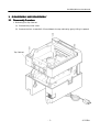
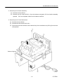
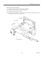
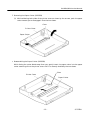
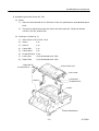
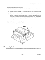
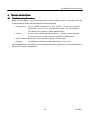
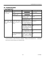
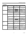
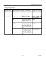
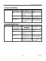
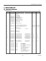
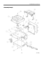
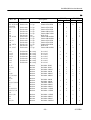
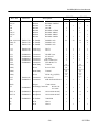
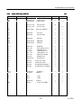
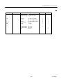
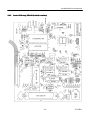
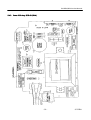
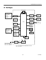
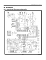
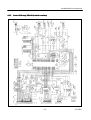
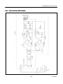
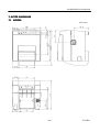
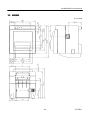
1
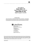
CITIZEN
Service Manual
Model: iDP3550/3551
Dot Matrix Printer
Rev. 1.00 Newly issued on May 10, 1999
Jap
Japan CBM
CBM Corporation
Information Systems Div.
iDP3550/3551 Service Manual
INTRODUCTION
This manual describes the disassembly, reassembly, and maintenance procedures of the dot impact printer iDP3550/3551. It is intended for field maintenance men.
FEATURES
This is a small-size dot impact printer developed for various data communication terminals, POS
terminals, kitchen-use printers, bank card, terminals, and so on.
Its abundant built-in features allow you to widely use this printer for different applications. Prior to using it, read and understand this manual thoroughly.
(1) Small size, light weight, and low price
(2) High-speed print (Bi-directional)
(3) Red and black print
(4) Very easy paper loading by the auto loading function
(5) Paper end detecting function
(6) Power supply through an AC adapter
–2–
CITIZEN
iDP3550/3551 Service Manual
CONTENTS
1.
HANDLING AND MAINTENANCE OF PRINTER ..........................................................................5
2.
SPECIFICATIONS ...............................................................................................................................6
2.1
3.
4.
5.
DISASSEMBLY AND REASSEMBLY ................................................................................................7
3.1
Disassembly Procedure...............................................................................................................7
3.2
Reassembly Procedure..............................................................................................................14
TROUBLESHOOTING ......................................................................................................................15
4.1
Troubleshooting Procedure.......................................................................................................15
4.2
Troubleshooting Guide..............................................................................................................16
SERVICE PARTS LIST ......................................................................................................................21
5.1
Parts List for Mechanism.........................................................................................................21
5.2
Disassembly Drawing ...............................................................................................................22
5.3
Parts List for PCB Assy ...........................................................................................................24
5.4
6.
7.
Basic Specifications ....................................................................................................................6
5.3.1
Control PCB Assy 3550-01 (R)/3550-02 (P) ................................................................24
5.3.2
Power PCB Assy 3535-03 .............................................................................................28
Parts Layout Drawing ..............................................................................................................30
5.4.1
Control PCB Assy 3550-01 (Serial Interface D-sub 25) .............................................30
5.4.2
Control PCB Assy 3550-02 (Parallel Interface)..........................................................31
5.4.3
Power PCB Assy 3535-03 (120V) .................................................................................32
5.4.4
Power PCB Assy 3535-03 (230V) .................................................................................33
DRAWING ...........................................................................................................................................34
6.1
Block Diagram..........................................................................................................................35
6.2
Circuit Diagram ........................................................................................................................36
6.2.1
Control PCB Assy 3550-01 (Serial Interface D-sub 25) .............................................36
6.2.2
Control PCB Assy 3550-02 (Parallel Interface)..........................................................37
6.2.3
Power PCB Assy 3535-03 (120V) .................................................................................38
6.2.4
Power PCB Assy 3535-03 (230V) .................................................................................39
OUTER DIMENSION ........................................................................................................................40
–3–
CITIZEN
iDP3550/3551 Service Manual
7.1
iDP3550 .....................................................................................................................................40
7.2
iDP3551 .....................................................................................................................................41
¨ For the printer mechanism (DP-400/410), see the separate Service Manual.
–4–
CITIZEN
iDP3550/3551 Service Manual
1. HANDLING AND MAINTENANCE OF PR
PRINTER
See the User’s Manual coming with the printer body.
–5–
CITIZEN
iDP3550/3551 Service Manual
2. SPECIFICATIONS
2.1 Basic Specifications
Model
iDP3550
IDP3551
Item
Printer mechanism
Character type: DP-654 series/Graphic type: DP-657series (CITIZEN)
Serial dot impact method (Bidirectional print), 2-pass graphic (UnidirecPrint method
tional print)
Print width
Character type: 63.6 mm/Graphic type: 58.7 mm
Print head
9 pins
Character type: Approx. 3.6 lines/second/Graphic type: Approx. 3
Print speed
lines/second
Print columns
40 columns
Character type: 1.36 mm(W) ´ 2.4 mm(H) (7 dots)
1.36 mm(W) ´ 3.1 mm(H) (9 dots)
Character size
Graphic type: 1.20 mm(W) ´ 2.4 mm(H) (7 dots)
1.20 mm(W) ´ 3.1 mm(H) (9 dots)
Character types
Alphanumeric, Katakana, International characters, Code page 850, 860,
863, 865, 852, 866, 857, Windows code
Line spacing
Character type: 4.23 mm (1/6 inch)/Graphic type: 2.82mm (1/9 inch)
Paper
Ordinary paper and non-carbon paper: 76 +/- 0.5 mm(W) ´ f83 mm(OD)
Special purpose ribbon cartridge:
Ink ribbon
Red/Black or Single Color (Black or Purple)
Interface
Serial(RS-232C), Parallel(CENTRONICS compliant)
CBM mode, STAR mode, ESC/POS mode
Command system
The user can select the mode with the DIP switch and preset jumpers.
Print function
On-line, self-test, and hex. dump print function
Provided by operating the power, LF, and SEL switches.
Input buffer
6K byte or 256 bytes (Selectable with the DIP switch)
Buffer backup function Within 24 hours (After 10 minutes or more of printer operation)
Drawer function
2-drawer, 1-drawer switch
Auto loading function Automatically feeds the paper by several lines when it is inserted.
Paper end detection
Stops printing when the paper has run out.
Paper near end detection Stops printing when the paper is running out.(Settable with a command)
Auto cutter
None
AC-134-E (Capable of partial and
full cut)
Winder
Special purpose winder AW-3-E (Option) that will be placed separately.
Supply voltage
120 V AC +/- 10 %, 50/60 Hz
230 V AC +/- 10 %, 50/60 Hz
Power consumption
Not printing: Approx. 10 W, Printing: Approx. 30 W
Weight
Approx. 2.8 kg
Approx. 3 kg
Outer dimensions
160(W)´212(D)´194(H) mm
160(W)´212(D)´173(H) mm
Operating temperature 0 to 40°C, 35 to 85 % RH (No dew condensation)
and humidity
Storage temperature -20 to 60 °C, 10 to 90 % RH (No dew condensation)
and humidity
EMI standard
U.S.A.: FCC Class-A
Europe: EN55022 Class-A, CE Marking
Safety standard
U.S.A., Canada: UL, c-UL Europe: TUV, GS
–6–
CITIZEN
iDP3550/3551 Service Manual
3. DISASSEMBLY AND REASS
REASSE
SSEMBLY
3.1 Disasse
ssembly Procedure
1. Removing the Top Cabinet
(1) Remove the printer cover.
(2) Remove the four screws (M3´12) and detach the top cabinet by gently lifting it upward
Top Cabinet
–7–
CITIZEN
iDP3550/3551 Service Manual
2. Removing the Chassis Assembly
(1) Remove the top cabinet.
(2) Remove the one screw (M3´6) - from the bottom and gently lift the chassis assembly
upward. Pull out the power cable from the bottom cabinet.
3. Removing the Printer Mechanism
(1) Remove the top cabinet.
(2) Remove the two screws (M3´14) ¬.
(3) Disconnect the two connectors and remove the printer mechanism by lifting its connector
side upward.
Bottom Cabinet
–8–
CITIZEN
iDP3550/3551 Service Manual
4. Removing the Power Board
(1) Remove the chassis assembly and then detach the control board.
(2) Remove the strain relief bushing of the power cable from the chassis with a special tool,
round nose pliers, or a similar tool.
(3) Remove the following four screws and detach the power board by lifting it upward while
pulling out the power switch from the chassis.
•Two screws (M4´6) that fasten the transformer
•One screw (M3´8) that fastens the heat sink
•One screw with outer-toothed washer (M4´6) that fastens the earth lug of the power
cable
Strain Relief Bushing
Power Switch
–9–
CITIZEN
iDP3550/3551 Service Manual
5. Removing the PE Sensor Assembly
(1) Remove the chassis assembly and the printer mechanism.
(2) Disconnect the one connector from the control board.
(3) Peel off the vinyl tape from the chassis.
(4) Slide the PE sensor assembly in the direction ¬ until its hooks come off the chassis, and
then remove it by turning it in the direction -.
Connector
Vinyl Tape
Chassis
Hooks
PE Sensor Assy
– 10 –
CITIZEN
iDP3550/3551 Service Manual
6. Removing the Auto Cutter AC-134
(1) Remove the top cabinet.
(2) Cut the cable tie ¬ to set the cable of the auto cutter AC-134, that is fastened to the
printer mechanism, free.
(3) Disconnect the one connector from the control board.
(4) Loosen (not remove) the one screw (M2.6´6) - and disengage both cutter BK from the
cutter BK mounting holes on the printer mechanism chassis to remove the auto cutter.
– 11 –
CITIZEN
iDP3550/3551 Service Manual
7. Removing the Paper Cutter (iDP3550)
(1) While widening both sides of the printer cover as shown by the arrows, push the paper
cutter toward you to disengage it from the two claws.
Claw
Printer Cover
Paper Cutter
· Reassembling the Paper Cutter (iDP3550)
While facing the cutter blade away from you, gently insert the paper cutter into the paper
cutter mounting slit on the printer cover until it is securely hooked by the two claws.
Claw
Printer Cover
Paper Cutter
– 12 –
CITIZEN
iDP3550/3551 Service Manual
8. Assembling the Auto Cutter AC-134
(1) Notes
1)
See the User's Manual of AC-130 Auto Cutter for specifications and detailed operations.
2)
The printer mechanisms that can mount the auto cutter AC-134 are as follows.
•DP-61*, DP-62*, and DP-65*
(2) Packing List (See Fig. 1.)
1)
Auto Cutter Unit AC-130 1 unit
2)
Hook L
1 pc.
3)
Hook R
1 pc.
4)
Cutter BK L
1 pc.
5)
Cutter BK R
1 pc.
6)
Screw (M2.6´6) 2 pcs.
7)
Lock Lever
(1 pc) (Attached to AC-130)
8)
Paper Gate
(1 pc) (Attached to AC-130)
Cutter BK R
Auto Cutter Unit
Screw M2.6´6
Lock Lever
Cutter BK L
Screw M2.6´6
Hook R
Hook L
Printer Mechanism
Fig. 1
– 13 –
CITIZEN
iDP3550/3551 Service Manual
(3) Assembling the Auto Cutter (See Fig. 1)
1)
Securely insert the claws of the hook L and hook R into the square holes on the
printer mechanism.
2)
Securely mount the cutter BK R on the auto cutter unit with the supplied screw
(M2.6´6).
3)
Temporarily mount the cutter BK L on the auto cutter unit with the supplied screw
(M2.6´6).
Insert the projections "A" and "B" of the cutter BK L and R into the
round holes on the printer mechanism to mount the auto cutter unit.
Engage both
ends of the lock lever with the notches "C" and "D" of the hook L and R, and then securely tighten the screw to fix the cutter BK L.
(4) How to Open the Auto Cutter (See Fig. 2.)
Push the handle and open the auto cutter.
Handle
Fig. 2
3.2 Reasse
ssembly Procedure
Reassemble each part in the reverse order of the disassembly procedure described in Section 3.1.
– 14 –
CITIZEN
iDP3550/3551 Service Manual
4. TROUBLESHOOT
OOTING
4.1 Troubleshoot
ooting Procedure
When a trouble occurs, confirm its phenomenon, locate a defective part in accordance with 4.2
Troubleshooting Guide, and troubleshoot as described below.
· Phenomenon:
Find a trouble phenomenon in this column.
If there are multiple
phenomena, take all the corresponding items into consideration.
This allows you to specify a hidden defective part.
· Cause:
Lists as many possible causes as possible.
Guess a trouble cause out
of them and take its check method to specify the trouble cause.
· Check Method: Describes a check method to specify a trouble cause.
· Remedy:
Troubleshoot by taking a remedy described in this column.
By troubleshooting in accordance with the above-mentioned procedure, you can troubleshoot efficiently with fewer misjudgments.
– 15 –
CITIZEN
iDP3550/3551 Service Manual
4.2 Troubleshoot
ooting Guide
· Power Supply Failure
Phenomenon
Cause
Check Method
No power
The AC cord is not con(POWER lamp not nected.
illuminated)
Not connected to the
terminal block (For
AC230V only)
Check whether any unThe fuse is gone.
specified power has
been used so far.
Check whether the
specified fuse is used.
The fuse immedi- The printer mechanism, The power is normally
ately goes again control PCB assy, or supplied when the caafter replacing with power PCB assy is de- ble is disconnected from
new on.
fective.
the printer mechanism.
(No operation is done.)
The power is normally
supplied when the cable
of the power PCB assy
is disconnected from the
control PCB assy.
The phenomenon does
not change after the
above-mentioned check.
Remedy
Connect the AC cord to
the AC outlet.
Connect to the terminal
block.
Use the specified AC
voltage.
Use the specified fuse.
Replace the
mechanism.
printer
Replace the control PCB
assy.
Replace the power PCB
assy.
The printer mechanism With a DC voltmeter, Replace the power PCB
or circuit drive power is measure the mecha- assy.
abnormal.
nism
drive
voltage
and circuit drive voltage.
¨ If the fuse is gone with the specified AC voltage supplied, it is likely that the printer mechanism,
control PCB assy, or power PCB assy is defective.
Replace either defective one.
Incidentally,
check the wiring of the drawer and interface cable.
– 16 –
CITIZEN
iDP3550/3551 Service Manual
· Printing failure
Phenomenon
No printing
Paint printout
Missing dots
Cause
Check Method
Remedy
Faulty AC supply volt- Check whether the
age
specified AC voltage is
used.
Faulty mounting or Check mounting and
connection
of
the connection
of
the
printer mechanism
printer mechanism.
Faulty printer mechanism
Non-recommended paper is used.
Use the specified AC
voltage.
Faulty ink ribbon
Replace the ink ribbon.
Check wear and tear of
the ink ribbon.
Low AC supply voltage
Check the supply voltage with an AC voltmeter.
Faulty connection of the Check whether the
printer mechanism
printer mechanism cable is properly connected.
Foreign substance is Check the head for any
attached to the print adhered foreign subhead.
stance.
Faulty print head
Bent ribbon mask
Check whether the ribbon mask is bent or not.
Badly blurred
printout
Mount
the
printer
mechanism properly.
Replace the printer
mechanism.
Replace it with the
specified paper.
Use the AC voltage
within the specified
range.
Connect the printer
mechanism cable properly.
Dip a cotton swab or
soft cloth in ethyl alcohol and wipe away the
foreign substance.
Replace the print head
or printer mechanism.
Correct the ribbon mask
to remove unwanted
bending.
Use the specified AC
voltage.
Faulty AC supply volt- Check whether the
age
specified AC voltage is
used.
Foreign substance is Check the head for any Dip a cotton swab or
attached to the print adhered foreign sub- soft cloth in ethyl alcohead.
stance.
hol and wipe away the
foreign substance.
Bad printing qual- Faulty paper
Check whether the pa- Replace it with the
ity
per meets the specifica- specified paper.
tions.
Faulty ink ribbon
Check wear and tear of Replace the ink ribbon.
the ink ribbon
Low AC supply voltage
Check the AC supply Use the AC voltage
voltage with an AC within the specified
voltmeter.
range
– 17 –
CITIZEN
iDP3550/3551 Service Manual
· Faulty carri
rriage mechanism
Phenomenon
Abnormal sound
Cause
Faulty connection of the
head connector
ERROR lamp illu- The print head does not
minated
move to the home position at power-on, or it
does not move.
Shear in printing
The paper is jamming.
Check Method
Remedy
Check the connection of
the head connector.
Check for any foreign
substance
within
a
movable range or any
wear of the gear, etc.
Turn off the power once,
and then on it again.
Connect the connector
properly.
Replace the print head
or printer mechanism.
If there is a shear in
printing, replace the
printer mechanism.
Faulty AC supply volt- Check whether the Use the specified AC
age
specified AC voltage is voltage.
supplied with an AC
voltmeter.
Foreign substance in Remove the printer Eliminate the foreign
the gear
mechanism and check substance.
for any foreign substance caught in the
gear, head motor gear,
or print head moving
part.
Broken gear
Remove the printer If broken, replace the
mechanism and check printer mechanism.
for any breakage of the
gear, head motor gear,
or print head moving
part.
– 18 –
CITIZEN
iDP3550/3551 Service Manual
· Paper feed
eed failure
Phenomenon
Cause
Check Method
Remedy
Paper is not fed or Faulty connection of the Check connection of the
fed irregularly
motor connector
motor connector.
Defective motor
Measure the supply
voltage with a DC voltmeter or oscilloscope.
Connect the connector
correctly.
If the supply voltage is
normal, replace the motor (printer mechanism).
Paper feed failure
Check whether or not Eliminate unnecessary
(Paper jam)
the paper is jamming or paper in the paper path
torn and caught in the and set paper properly.
paper path.
Low AC supply voltage
Check the AC supply Use the specified AC
voltage with an AC voltage.
voltmeter.
Foreign substance in Remove the printer Eliminate the foreign
the gear
mechanism and check substance.
for any foreign substance caught in the
gear or motor gear.
Broken gear
Remove the printer If broken, replace the
mechanism and check printer mechanism.
for any breakage of the
gear or motor gear.
· Faulty sensors
Phenomenon
Cause
Check Method
Does not detect Faulty paper sensor
presence of paper.
Replace the printer
mechanism and check if
the replaced one functions properly.
Check whether the ERROR
lamp
flickers
when paper is out.
Foreign substance, etc. Check for any foreign
caught by the sensor
substance.
Remedy
Replace the
mechanism.
printer
Eliminate the foreign
substance.
Does not detect Faulty paper near-end
Replace the paper nearpaper
near-end sensor
end sensor.
status.
Faulty connection of the Check connection of the Connect the connector
paper near-end sensor
connector.
correctly.
Foreign substance, etc. Check for any foreign Eliminate the foreign
caught by the sensor
substance.
substance.
¨ If the no-paper condition is not detected while the printer is running out of the recording paper, it
will print without the paper, leading to a trouble of the head, and so on.
– 19 –
CITIZEN
iDP3550/3551 Service Manual
· Faulty auto cutte
tter (iDP3551 only)
Phenomenon
Cause
Check Method
Remedy
Does not cut paper.
Faulty connection of the
motor connector
Faulty AC supply voltage
Check connection of the
motor connector.
Check whether the
specified AC voltage is
supplied with an AC
voltmeter.
Connect the connector
correctly.
Use the specified AC
voltage.
Defective motor
Measure the supply
voltage with a DC voltmeter or oscilloscope.
Check whether or not
the paper is jamming or
torn and caught in the
paper path.
If the supply voltage is
normal, replace the motor (auto cutter).
Eliminate unnecessary
paper in the paper path
and set paper properly.
Check Method
Remedy
Paper feed failure
(Paper jam)
· Faulty winder (When AW-3 is used)
Phenomenon
Cause
Does not wind pa- Paper end is not corper.
rectly inserted into the
slit of the winder reel.
Faulty connection of the
motor connector
Faulty AC supply voltage
Paper feed failure
(Paper jam)
Defective motor
Insert paper into the
slit correctly.
Check connection of the
motor connector.
Check
whether
the
specified AC voltage is
supplied with an AC
voltmeter.
Check whether or not
the paper is jamming or
torn and caught in the
paper path.
Measure the supply
voltage with a DC voltmeter or oscilloscope.
– 20 –
Connect the connector
correctly.
Use the specified AC
voltage.
Eliminate unnecessary
paper in the paper path
and set paper properly.
If the supply voltage is
normal, replace the
motor assy AW.
CITIZEN
iDP3550/3551 Service Manual
5. SERVICE PARTS LIST
5.1 Parts List for Me
Mechanism
EXPLODED VIEW
1/1
Ref. No.
Parts No.
Description
1
2
3
4
5
6
7
8
9
E4002-430
E6601-220
E4035-690
E40000290
E66201-060
E62020390
E62040550
E6220-220
Chassis
Vinyl Tape
Printer Stand
Ground Plate
PE Mechanism Assy
Top Cabinet Assy
Bottom Cabinet Assy
Printer Cover Assy
Paper Cutter
10
E62040340
Printer Cover AC
11
11
E6101-115
E6101-120
Strain Relief Bushing (HEYCO)
Strain Relief Bushing (HEYCO)
12
13
AC-134
14
15
E6310-010
E4002-560
Rear Cover
Shield Plate
16
16
16
16
16
16
E77001-465
E77001-470
E77001-475
E77001-480
E77001-485
E77001-490
Control PCB Assy
Control PCB Assy
Control PCB Assy
Control PCB Assy
Control PCB Assy
Control PCB Assy
17
17
E40000305
E40000315
Power PCB Assy
Power PCB Assy
30
31
32
33
34
76G22579
76G22796
76G38641
76G72589
76G42959
Screw
Screw
Screw
Screw
Screw
35
36
76G29560
76G42966
Screw
Screw
iDP3550 iDP3551
1
1
2
1
1
1
1
1
(1)
1
1
2
1
1
1
1
1
DP-654, 657
Auto Cutter Unit
(1)(JPN,USA) (1)(JPN,USA)
(1) (EUR) (1) (EUR)
(1)
(1)
1
1
1
1
1
3550-01(Serial EUR)
3550-01(Serial USA)
3550-02(Parallel)
3551-01(Serial EUR)
3551-01(Serial USA)
3551-02(Parallel)
(1)
(1)
(1)
(1)
(1)
(1)
(1)
(1)
(1)
(1)
(1)
(1)
3535-03(230V)
3535-03(120V)
(1)
(1)
(1)
(1)
7
1
2
2
1
7
1
2
2
1
4
1
4
1
AC-134-E
M3´6 Tapping
M3´8 Tapping
M3´14 Tapping (with Washer)
M4´6 Tapping
M4´6 Tapping (with OuterToothed Lock Washer)
M3´12 Tapping
M3´6 Tapping (with OuterToothed Lock Washer)
– 21 –
CITIZEN
iDP3550/3551 Service Manual
5.2 Disasse
ssembly Drawing
· Disassembly Drawing-1
– 22 –
CITIZEN
iDP3550/3551 Service Manual
· Disassembly Drawing-2
– 23 –
CITIZEN
iDP3550/3551 Service Manual
5.3 Parts List for PCB As
Assy
5.3.1
Control PCB Assy
ssy 35503550-01 (R)/3550
3550-02 (P)
Ref. No
Parts No.
Description
1/4
iDP3550
R
P
iDP3551
R
P
SW1,2
E5102-450
Switch
SKHHNH
2
2
2
2
IC1
IC2
IC3
IC4
IC6
IC7
IC7
IC8
IC8
IC9
IC10
IC11
IC11
IC12
404PC-10
E 107-370
E 107-350
E2010610
E2002-670
E 202-950
E2010630
E 202-950
E2010620
E2010101
E2016110
E2016110
E2010640
E2010640
CPU
EPROM
SRAM
TTL IC
Reset IC
I/F-IC
TTL IC
I/F-IC
TTL IC
HCMOS
TTL IC
TTL IC
TTL IC
TTL IC
404PC-10
M27C512B
TC55257DPL-85L
SN74LS14AP
M51953BL
MAX202CPE
SN74LS373AP
MAX202CPE
SN74LS74AP
TC74HC00AP
SN74LS04AP
SN74LS04AP
SN74LS00AP
SN74LS00AP
1
1
1
1
1
1
1
1
1
1
1
1
1
1
1
1
1
1
1
1
1
1
TA1
TA2
TA3
E 390-300
E 390-370
E 390-230
Tr. Array
Tr. Array
Tr. Array
MTA001M F4002
M54567P
TA8428K
1
1
1
1
1
1
1
1
1
1
TR1
TR2-6,12
TR7
TR8
TR9-11
E 379-129
E 359-090
E 359-200
E 358-040
E 359-170
Transistor
Transistor
Transistor
Transistor
Transistor
2SD1292R
2SC1740SR
2SA1458
RN1002
2SC4671-AN
1
6
1
1
3
1
6
1
1
3
1
6
1
1
3
1
6
1
1
3
D1,2
ZD1
LED1,2
Xtal
DSW1
DSW2
BZ
E 400-460
E406-505
E480-390
E 501-410
E 5103-490
E 5103-510
MEB12C5
Diode
Z. Diode
LED
X'tal
DIP SW.
DIP SW.
Buzzer
1S2076
RD20EB2
SEL2410E
CST16.00MXW0C4
KSD-10
KSD-8
MEB-12C-5
2
1
2
1
1
1
1
C1
C2
C3,4,17-21,25
CP1-6
C5,7,8
C6,9,10
C11
C11
E2010-960
E2010-920
E 2220-170
Ele. Cap.
Ele. Cap.
C. Cap.
16YK100M
35YK47M
DD308-63F104Z50
E2220-110
E2220-100
E2220-210
E2220-110
C. Cap.
C. Cap.
C. Cap.
C. Cap.
DD104-63B102K50
DD106-63F103Z50
DD804-63B222Z50
DD104-63B102K50
– 24 –
1
1
1
1
1
1
1
1
1
1
1
1
1
1
1
1
1
1
1
1
1
2
1
2
1
1
1
1
1
1
1
14
1
1
14
1
1
14
1
1
14
3
3
1
3
3
3
3
1
3
3
1
2
1
1
1
1
2
1
1
1
CITIZEN
iDP3550/3551 Service Manual
2/4
iDP3551
R
P
11
11
Parts No.
C12-16,22-24
26,34,38
C12,16,22
C13
C14
C15
C23
C24, 26-28
C27
C28,30
C29
C29, CP7-9
C31
C33, 35-37
E2220-170
C. Cap.
DD308-63F104Z50
E2220-100
E2220-100
E2220-210
E2220-120
E2010-950
E2220-200
E2220-110
E2220-100
E2220-100
E2220-170
E2010-950
E2220-200
C. Cap.
C. Cap.
C. Cap.
C. Cap.
Cap.
C. Cap.
C. Cap.
C. Cap.
C. Cap.
C. Cap.
Cap.
C. Cap.
DD106-63F103Z50
DD106-63F103Z50
DD804-63B222Z50
DD104-63B471K50
FS0H-473Z
DD104-63B101K50
DD104-63B102K50
DD106-63F103Z50
DD106-63F103Z50
DD308-63F104Z50
FS0H-473Z
DD104-63B101K50
RA1
RA1,2
RA2,3
RA3,6
RA4
RA4
RA7
E3500-040
E3500-080
E3500-050
E3500-040
E3500-290
E3500-050
E3500-290
Re. Array
Re. Array
Re. Array
Re. Array
Re. Array
Re. Array
Re. Array
M9-1-103J
M9-1-332J
M5-1-103J
M9-1-103J
M5-1-332J
M5-1-103J
M5-1-332J
1
Resistor
Resistor
Resistor
Resistor
Resistor
Resistor
RD25M10-1KWJ
RD25M10-1KWJ
RD25M10-33KWJ
RD25M10-180WJ
RD25M10-10KWJ
RD25M10-10KWJ
2
Resistor
Resistor
Resistor
Resistor
Resistor
Resistor
Resistor
RD25M10-100WJ
RD25M10-100WJ
RD25M10-10KWJ
RD25M10-62KWJ
RD25M10-62KWJ
RD25M10-3.3KWJ
RD25M10-3.3KWJ
Resistor
Resistor
Resistor
Resistor
RD25M10-3.3KWJ
RD25M10-68KWJ
RD25M10-68KWJ
RD25M10-330KWJ
R1,17
RA1,16
R2
R3
R4,18
R5,7,9,19,23
28
R5,23
R6
R6,8,17,24,29
R7
R8
R9,14,22,31
R10,11,15,21
30
R12,16,29
R12
R13
R13,28
Description
iDP3550
R
P
Ref. No
3
3
1
1
1
1
4
1
1
1
4
1
2
1
2
1
4
1
4
4
1
4
1
2
2
2
2
2
1
2
1
1
1
1
1
2
6
1
1
2
2
1
1
2
1
1
2
6
2
1
2
1
5
1
1
5
2
1
1
2
5
1
1
4
5
3
5
4
5
3
1
1
1
1
2
2
3/4
– 25 –
CITIZEN
iDP3550/3551 Service Manual
Ref. No
Parts No.
R14,26
R19
R20
R22
R24,25
R25,26
R27
Description
iDP3550
R
P
iDP3551
R
P
2
Resistor
Resistor
Resistor
Resistor
Resistor
Resistor
Resistor
RD25M10-330KWJ
1.5W-1W
1.5W-1W
RD25M10-4.7KWJ
RD25M10-10KWJ
RD25M10-10KWJ
RD25M10-330KW
2
1
1
1
1
1
1
1
1
1
1
2
1
2
1
LB1-18,23-26
LB19-22
LB27
E4009-510
E4009-510
E4009-510
Fe. Beads
Fe. Beads
Fe. Beads
BL02RN1-A62
BL02RN1-A62
BL02RN1-A62
22
22
22
4
22
4
1
CA1
CA2
E4900-620
E4900-630
Cord Assy
Cord Assy
25-0371
25-0372
1
1
1
1
1
1
1
1
CN1
CN2
CN3
CN4
CN4
(CN4)
E48000260
E48000940
E48000265
E48000280
E48000600
Connector
Connector
Connector
Connector
Connector
Metal Stay
B5P-SHF-1AA
5267-02A-X
5045-04A
FCN-674J025-L/C
57GE-40360-751
17L-002A
1
1
1
1
1
1
1
1
1
1
1
1
1
1
(CN4)
Screw
(CN4)
Metal Stay
(CN4)
CN5
CN6
JP102
SC1
Screw
E4800-945
E48000565
E48000860
Connector
Connector
M2.6´12 ZNP
17L-002C
UNC#4-40´12(ZNP)
5267-04A-X
JACK-285D-9660J-101
1
1
(2)
(2)
(JPN,EUR)
(JPN,EUR)
(2)
(2)
(JPN,EUR)
(JPN,EUR)
(2)
(2)
(USA)
(USA)
(2)
(2)
(USA)
(USA)
1
1
1
1
1
1
Jumper
f0.7mm 10mm
Switching Connector
00-8261-2433-10-806
1
1
1
1
1
1
REC1-4
REC5-8
E48000855
E48000855
Receptacle
Receptacle
20-8261-0249-06-807
20-8261-0249-06-807
4
4
4
4
4
4
ICS
E48000870
IC Socket
87-2806S04
1
1
1
1
PCB
PCB
3550-01
3550-02
1
PC
PC
– 26 –
1
1
1
CITIZEN
iDP3550/3551 Service Manual
4/4
Ref. No
iDP3550
R
P
iDP3551
R
P
2
2
2
2
4
2
2
2
2
4
Insu-Lock Tie T18S
1
1
1
1
ROM Label
1
1
1
1
Parts No.
Description
Screw
Screw
Nut
E8035-010
(IC2)
M3´10 ZNP (C)
M3´8 (B-506)
M3 ZNP (C)
PDL-65
– 27 –
CITIZEN
iDP3550/3551 Service Manual
5.3.2
Power PCB Ass
Assy
ssy 353535-03
Ref. No
TR
TR
Parts No.
1/2
Description
USA
EUR
Transformer
Transformer
25-0289 120V
25-0290 230V
(1)
Power Cord
Power Cord
25-0184 120V
25-0185 230V
(1)
NF
Noise Filter
PLAA3221R0D01
1
1
IC1
IC2
Regulator
Regulator
M5231TL
µPC2405AHF
1
1
1
1
TR1
Transistor
2SB1340
1
1
DS1
DS2
Diode Stack
Diode Stack
2KBP02M
KBP02M
1
1
1
1
C1,2
C5
C6
C7
C8
C9
C10
C11
Film Cap.
Ele. Cap
C. Cap.
Ele. Cap.
Ele. Cap.
Ele. Cap.
Ele Cap.
Mylar Cap.
PHE830M
63PNJ-2200A 25´25
DD804B101K50
50YK1M-TA-5´11
35YK470M 10´16
SME16VB-3300M
CESME1C101
DMY21H104
2
1
1
1
1
1
1
1
2
1
1
1
1
1
1
1
R1
R2
R3
R4
Resistor
Resistor
Resistor
Resistor
RD25T(26)-330W
RD25T(26)-560W
SN14K2ET26A20KW F
SN14K2ET26A1.54KW F
1
1
1
1
1
1
1
1
CN1
CN5
Connector
Terminal
F5P-SHVQ
GSK801
1
1
1
F1,3
F1
Fuse
Fuse
235001
218500
2
1
1
SW
Heat Sink
Switch
50-0079
SF-W1P1A-01BB2
1
1
1
1
– 28 –
(1)
(1)
CITIZEN
iDP3550/3551 Service Manual
2/2
Ref. No
Parts No.
Description
Adhesive Tape f10mm L=10mm
FH2
FH1,3
PCB
Jumper
Screw
Screw
Fuse Holder
PCB
f0.7mm L=18mm
M3´8 B Tight Znp(c)
M3´8 B Tight (B-567)
F218P
3535-03
Cord Bushing SR-4N-4
Cord Bushing SR-5N-4
Tie
CV-075
– 29 –
USA
EUR
1
1
1
2
1
4
1
1
2
1
4
1
1
1
1
CITIZEN
iDP3550/3551 Service Manual
5.4 Parts Layout Drawing
5.4.1
Control PCB Assy
ssy 3550550-01 (Serial Interface D-sub 25)
25)
– 30 –
CITIZEN
iDP3550/3551 Service Manual
5.4.2
Control PCB Assy
ssy 35503550-02 (Paralle
llel Interface)
– 31 –
CITIZEN
iDP3550/3551 Service Manual
5.4.3
Power PCB Ass
Assy
ssy 353535-03 (120
120V)
– 32 –
CITIZEN
iDP3550/3551 Service Manual
5.4.4
Power PCB Ass
Assy
ssy 353535-03 (230
230V)
– 33 –
CITIZEN
iDP3550/3551 Service Manual
6. DRAWING
The following lists the reference drawings for maintenance, and so on.
• Block diagram
• Circuit diagrams for the following circuits
• Control PCB Assy (Serial Interface)
• Control PCB Assy (Parallel Interface)
• Power PCB Assy
– 34 –
CITIZEN
iDP3550/3551 Service Manual
6.1 Block Diagram
OSC16MHz
Parallel
(CENTRONICS
Compliant)
Serial
(RS-232C Compliant)
Winder
Control
Interface
Cutter
Control
Paper
Near-end
Control
Drawer
Control
CPU
Operation
Panel
(Option)
Auto
Cutter
(iDP3551 only)
Drawer
DIP Switch
Print Head
Driver
Printer
Mechanism
DP-654C
or
DP-657G
Winder
ROM
DC Motor/
LF Solenoid/
CC Solenoid/
Drivers
RAM
Battery
Back-up
Mechanism
Control
Signals/
PE Signal
Reset
Vp
Filter
Power Supply
120 V AC, 50/60 Hz
230 V AC, 50/60 Hz
Vcc
Power
Supply
Vp: For mechanism drive/drawer kick-out
Vcc: For circuit
– 35 –
CITIZEN
iDP3550/3551 Service Manual
6.2 Circuit Diagram
6.2.1
Control PCB Assy
ssy 35503550-01 (Serial Interface D-sub 25)
25)
– 36 –
CITIZEN
iDP3550/3551 Service Manual
6.2.2
Control PCB Assy
ssy 35503550-02 (Paralle
llel Interface)
– 37 –
CITIZEN
iDP3550/3551 Service Manual
6.2.3
Power PCB Ass
Assy
ssy 353535-03 (120
120V)
– 38 –
CITIZEN
iDP3550/3551 Service Manual
6.2.4
Power PCB Ass
Assy
ssy 353535-03 (230
230V)
– 39 –
CITIZEN
iDP3550/3551 Service Manual
7. OU
OUTER DIMENSION
7.1 iDP3550
Unit: mm
– 40 –
CITIZEN
iDP3550/3551 Service Manual
7.2 iDP3551
Unit: mm
– 41 –
CITIZEN