1
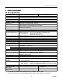
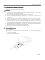
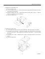
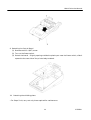
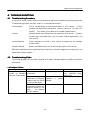
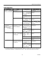
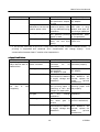
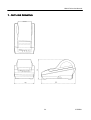
CITIZEN
Service Manual
Model : CBM-270
Line Thermal Printer
Rev. 1.00
Newly issued on 05. Jan. 1999
Japan CBM Cor poration
Infor mation Systems Div.
CBM-270 Service Manual
INTRODU
ODUCTION
This manual describes the disassembly, reassembly, and maintenance procedures of the Line
Thermal Printer CBM-270. It is intended for field maintenance men.
FEATURES
This small line thermal printer is designed for various types of data communication terminals
and measuring instrument terminals.
Its abundant built-in features allow you to widely use
this printer for different applications.
Prior to using it, read and understand this manual
thoroughly.
(1)
Small, lightweight, and installable in a narrow area
(2)
High speed and low noise, owing to line thermal print
(3)
Long-life printing head and high reliability, owing to the simple mechanism
(4)
Easy paper-loading, owing to the auto-loading function
(5)
Built-in input buffer
(6)
Capable of printing a bar code (Special command)
(7)
Capable of accommodating both thermal paper and label paper
(8)
A little discharge (1 sheet) of the label paper at power-on or paper replacement
(9)
Capable of printing in two colors (when special paper is used)
(10) External characters registration function (94 kanji characters, 95 ANK characters)
2
CITIZEN
CBM-270 Service Manual
CONTENTS
1. HANDLING AND MAINTENANCE OF PRINTER ..........................................................................4
2. SPECIFICATIONS .............................................................................................................................5
2.1 Basic Specifications ................................................................................................................................... 5
2.2 Paper Specifications (Recommended Paper)............................................................................................ 6
3. DISASSEMBLY AND REASSEMBLY ...............................................................................................7
3.1 Disassembly Procedure ............................................................................................................................. 7
3.2 Reassembly Procedure ............................................................................................................................ 12
4. TROUBLESHOOTING ....................................................................................................................13
4.1 Troubleshooting Procedure ..................................................................................................................... 13
4.2 Troubleshooting Guide ............................................................................................................................ 13
5. SERVICE PARTS LIST ....................................................................................................................19
5.1 Parts List for Mechanism ....................................................................................................................... 19
5.2 Disassemble Drawing.............................................................................................................................. 20
5.2.1 Drawing for Operation Panel Board .............................................................................................. 21
5.3 Parts List for Control Board ................................................................................................................... 22
5.4 Parts Layout Drawing............................................................................................................................. 24
5.4.1 Serial Interface (Parts side) ........................................................................................................... 24
5.4.2 Serial Interface (Solder side).......................................................................................................... 25
5.4.3 Parallel Interface (Parts side) ........................................................................................................ 26
5.4.4 Parallel Interface (Solder side)....................................................................................................... 27
6. DRAWING ........................................................................................................................................28
6.1 Block Diagram ......................................................................................................................................... 28
6.2 Circuit Diagram....................................................................................................................................... 29
6.2.1 Serial Interface (CBM270-RF) ....................................................................................................... 29
6.2.2 Parallel Interface (CBM270-PF) .................................................................................................... 30
7. OUTLINE DRAWING ......................................................................................................................31
3
CITIZEN
CBM-270 Service Manual
1. HANDLING AND MAINTENANCE OF PR
PRINTER
See "Unpacking" and "OPERATION" in the User's Manual accompanying the printer body.
4
CITIZEN
CBM-270 Service Manual
2. SPECIFICATIONS
2.1 Basic Specifications
Item
Printing system
Printing width
Dot density
Paper feed pitch
Printing speed
Printing
digits
character size
Line interval
Model
and
Character types
Character code
Bar code type
Paper
(See Paper Specifications)
Interface
Input buffer
Download characters
Auto-loading
Paper end function
Paper near end function
Label detecting function
Printing color
AC adapter
Type
AC cord
Supply voltage
Power consumption
Weight
Outer dimensions
Operating temperature and
humidity
Storage temperature and
humidity
Reliability
EMI
Applicable standard
(Main body)
Applicable standard
(Power source)
*1
*1
CBM-270-RF120-*
CBM-270-RF230-*
CBM-270-PF120-*
CBM-270-PF230-*
Line thermal dot printing
48 mm (384 dots/line)
8 dots/mm (Width, Length)
0.125 mm
Approx. 11 lines/sec. (At maximum)
32 columns (12 ´ 24 Font A) 1.25 ´ 3.00 mm
42 columns (9 ´ 24 Font B) 0.88 ´ 3.00 mm
Initial value: 4.23 mm (1/6 inch)
Can be set with a command (1/360 inch at minimum)
Alphanumerals, symbols, international characters
(Choose from 10 countries)
Domestic characters, IBM characters #2 (Choose either)
UPC-A/E, JAN(EAN) 13-/8-column, ITF, CODE 39, CODE 128, CODABAR
Thermal paper roll : 58 + 0/- 1 mm xf83 (max.) mm, 60~75mm thick
Thermal label paper : 58 + 0/- 1 mm x f83 (max.), 150mm thick (max.)
(L and M Spec. only)
Label width: 56 mm (max.)
Label length: 25 mm/sh. (min.)
Serial (RS-232C), Parallel (CENTRONICS compliant)
2 KB
Font A, B: 95 characters each
Provided (Can be enabled/disabled with the DIP switch)
Provided
Provided (Can be enabled/disabled with the DIP switch)
Capable of selecting label interval detection, black mark detection, or none.
Capable of printing in two colors (red/black) with the special thermal paper.
Rated input
: 100~240 V, 50/60 Hz, 40 VA
Rated output : 7.2 V DC, 2 A
27 AD
2-core cord (Depends on the destination)
120 V AC +/- 10%, 60 Hz
230 V AC +/- 10%, 50/60 Hz
At non-printing: Approx. 2 W
At printing: Approx. 15 W (approx. 20 W at maximum)
Main body: Approx. 600 g (Paper roll excluded)
AC adapter: Approx. 350 g
106 (W) ´ 184 (D) ´ 110 (H) mm
5~40 °C, 35~85 % RH (No dew condensation)
-20~60°C, 10~90% RH (No dew condensation)
Printing head life: (25°C)
Pulse resistance : 50 million pulses or more (Print rate 12.5%)
Wear resistance : 50 km or more (With recommended thermal paper at normal
temperature and humidity)
FCC Class-A
EN55022 Class-A
GS, CE Marking
UL, C-UL
GS
* *1 indicates the standard satisfied when the AC adapter 27AD is used.
* GS and CE Marking are satisfied when the main body and AC adapter are combined.
5
CITIZEN
CBM-270 Service Manual
2.2 Paper Specifications
2.2.1
Recomme
mmended Paper
(1) Thermal paper roll
·Type
: Thermal paper
·Paper width
: 58 + 0/- 1 mm
·Paper thickness
: 60~75mm
·Roll diameter
: f83 mm or less
·Printing surface
: Outside of the roll (Surface)
·Recommended paper
: TF50KS-E2C (Monochrome) made by NIPPON SEISHI or its
equivalent
735FA(2-color, Black based) made by RICOH or its equivalent
PB670(2-color, Red based) made by MITSUBISHI SEISHI or its
equivalent
·Core
:f12 mm(Inner dia.), f18 mm (Outer dia.)
(2) Thermal label paper(L and M spec. only)
·Type
: Thermal paper (Printing surface)
·Paper width
: 58 + 0/- 1 mm
·Label width
: 56 mm or less
·Label length
: 25~300 mm (For label interval detection)
25~300 mm (For black mark detection) * Black mark section excluded
·Label interval
: 3~300 mm (Black mark interval for the black mark detection)
·Black mark width
: 15 mm or more (From the center of the paper, black paper only)
·Paper thickness
: 150mm or less
·Roll diameter
: f83 mm or less (Depends on the outer diameter of the core)
·Printing surface
: Outside of the roll (Surface)
·Recommended paper
: For label interval detection
KPT86S P22 G63BC (Monochrome) made by OHJI TUCK or
its equivalent
For black mark detection
KPT865P (Monochrome) made by OHJI TUCK or its equivalent
·Core
: f12 mm or more (Inner dia.), 3 mm thick
CAUTION:
1. Use of non-specified paper may cause irregularity of print density. If this is the case, use the
DIP switch to reset print density. (See 5. DIP SWITCH SETTING)
2. Do not paste the paper to the core.
3. If the paper comes in contact with a chemical or oil, it may discolor or lose a record.
4. Do not rub the paper surface strongly with a nail or hard metal. It may discolor.
5. Discoloring starts at about 70°C. Watch out for effects of heat, humidity, light, and so on.
6. Do not use the label paper when the printer has been set for thermal paper, and vice versa.
Be careful not to mistake a type of label paper. It could cause malfunctioning or damage the
printing head.
6
CITIZEN
CBM-270 Service Manual
3. DISASSE
SSEMBLY AND REASSE
SSEMBLY
In case of maintenance work, observe the following:
CAUTION
(1) If the printer functions properly, do not disassemble, reassemble, or adjust it.
Particularly,
do not loosen each setscrew unless required.
(2) After inspecting the printer, be sure to confirm that it is free from error.
(3) Never try to print without setting the printing paper in the printer.
Confirm that it is
properly set.
(4) In case of maintenance work, be careful not to leave the used parts or screws in the printer.
(5) When handling the thermal head or control board, do not wear the gloves which will easily
cause static electricity. Prior to handling it, discharge static electricity from your body.
Also, never conduct maintenance work in a place where the printer will be easily electrified.
(6) When disassembling and reassembling, check the cords and boards for any damage, and do
not cable or fix them in an inappropriate manner by force.
(7) Never carry out maintenance work with the power turned on.
3.1 Disasse
ssembly Procedure
1. Prior to Disassembly
(1) Disconnect all the cables from the rear of the main body.
For your safety, unplug a power
cord from a plug socket.
(2) Leave the printer cover attached.
7
CITIZEN
CBM-270 Service Manual
2. Removing the Screws from the Bottom of the Main Body
(1) Turn over the printer body.
(2) Remove two M3 ´ 10 (BT) screws. Then, turn back the printer body to its original position.
Do this, holding its upper and bottom covers.
3. Detaching the Printer Cover and Paper Roll
(1) Detach the printer cover. Put a finger, etc. on a convexed part from the rear of the printer
body and lift.
(2) Detach the paper roll.
If the paper roll has been set in the printer, cut he surplus paper
and detach it gently.
See "HOW TO REMOVE REMAINING PAPER ROLL" in the
USER'S MANUAL.
8
CITIZEN
CBM-270 Service Manual
4. Detaching the Platen Roller Unit
(1) Raise the head-up lever.
(2) Unlock the platen roller unit. Pull up the blue levers on both sides of the platen roller unit,
while opening them outside.
(3) Detach the platen roller unit.
Hold the blue levers on both sides of pull up.
Keep the
platen unit carefully so as not to damage it.
(4) Lower the head-up lever.
5. Detaching the Upper Cover
(1) Lift the upper cover from the rear of the printer body. When this is done, lift it gently.
(2) Disconnect all the connectors.
Holding up the upper cover, disconnect all the connectors
from the control board. Hold the base of the connector to disconnect it. Pulling the cable
will snap it.
(3) Disconnect the FG cable.
Remove one M3 ´ 8 (BT) screw used to secure it to the control
board.
(4) Detach the upper cover.
9
CITIZEN
CBM-270 Service Manual
6. Detaching the NPE Sensor Unit
(1) Remove one M3 ´ 10 (BT) screw used to secure the NPE sensor unit.
(2) Pull out a cable.
7. Detaching the Operation Panel Board
(1) Remove two M2.6 ´ 8 (BT) screws.
Turn over the upper cover and unscrew the operation
panel board.
(2) Detach the operation panel board.
8. Detaching the Printer Mechanism
(1) Remove four M2.6 ´ 8 (BT) screws used to secure the printer mechanism. Remove two
screws each from the front and back.
(2) Pull out the printer mechanism. Pull it out gently to the paper holder side (front) without
pulling a cable. If the label sensor is attached, separate it from the printer mechanism.
10
CITIZEN
CBM-270 Service Manual
9. Detaching the Control Board
(1) Remove one M3 ´ 8(BT) screw.
(2) Turn on the Power switch.
(3) Detach the board. Slightly opening outside the plastic part near the Power switch, slide it
upward to the near side of the printer body to detach.
10. Detaching the shielding plate.
* For Steps 5 to 9, carry out only those required for maintenance.
11
CITIZEN
CBM-270 Service Manual
3.2 Reassembly Procedure
Reassemble the disassembled parts in the reverse order of the disassembly procedure described
in 3.1.
CAUTION:
1. Route the cables very carefully so that they will not be caught.
·The flat cable should be located on the board side.
·Take care that the NPE sensor will not be cabled above the DIP switch.
2. Tighten the screws firmly, but avoid tightening them too hard.
3. Use only the attached screws.
There are several kinds of screws used.
If they are
unscrewed, be sure to put them back in their original places.
4. After reassembly, be sure to check prior to turning on the power.
12
CITIZEN
CBM-270 Service Manual
4. TROUBLESHOOTING
4.1 Troubleshoot
ooting Procedure
If the printer has a trouble, confirm its phenomenon, determine a defective part according to 4.2
Troubleshooting Guide, and then, repair it in the specified manner.
· Phenomenon
Find a corresponding trouble phenomenon in this column.
If there
multiple corresponding phenomena, confirm taking all of them into
account. This allows you to determine a hidden defective part.
· Cause
Possible causes are listed as many as possible in this column. Project a
trouble cause and determine it by the check method described in the
next column.
· Check Method
Check methods are listed in this column to determine the relevant
trouble cause.
· Repair Method
Repair the defective part in the manner described in this column.
Efficient troubleshooting is enabled without making a erroneous judgment by repairing in the
above-mentioned procedure.
4.2 Troubleshoot
ooting Guide
The following table lists the check methods and repair methods based on possible phenomena
and causes.
· AC Adapter Failure
Phenomenon
Cause
Check Method
The power cannot be The AC cord is not
turned on (POWER connected.
--lamp not illuminated)
The
voltage
is Use a voltmeter to
abnormal.(It is slightly measure
a
supply
higher than the rating voltage.
in the no-load state)
The AC adapter was
connected to(used for)
another device in the
--past.
12. Replace
the AC adapter.
13
Repair Method
Connect the AC cord to
the
specified
plug
socket, etc.
Replace the AC adapter.
Replace the AC adapter.
CITIZEN
CBM-270 Service Manual
· Power Supply Failure
Phenomenon
Cause
Check Method
The power cannot be The AC adapter is not
--turned
on.(POWER connected.
lamp not illuminated)
The fuse is gone.
Check whether or not
the
non-specified
power supply was used
in the past.
Check whether or not
the specified fuse is
used.
Check whether or not
Others
the specified power
supply is used.
Check whether or not
the cable or connector
of the operation panel
board is connected.
The fuse blows out The
printer The power is turned on
immediately
if mechanism or control by disconnecting the
replaced. It blows out board is defective.
cable of the printer
during operation.
mechanism.
(F1 blows out)
(Does not operate)
The
phenomenon
remains
unchanged
after
the
abovementioned check.
Ditto (F2 blows out) The control circuit is Measure
a
circuit
corrupt. The voltage voltage
with
a
is abnormal.
voltmeter, and it is
normal.
The voltage is higher.
Ditto (F3 blows out)
Repair Method
Connect the specified
AC adapter.
Use the specified AC
adapter.
Use the specified fuse.
Use the specified AC
adapter.
Replace the cable of
the operation panel
board.
Connect the
connector.
Replace the printer
mechanism.
Replace
board.
the
control
Replace
board.
the
control
Replace Tr1, ZD2, or a
peripheral circuit part.
The voltage is lower.
Replace the control
board.
The motor or driver of The power is turned on Replace the printer
the printer mechanism by disconnecting the mechanism.
is defective.
motor cable.
(Does not operate)
The
phenomenon Replace the motor
remains
unchanged driver or control board.
after
the
abovementioned check.
* If the fuse is gone while using the specified AC adapter, it is likely that the printer mechanism or
control board is defective. Replace either of them. Also, check the wiring of the interface.
14
CITIZEN
CBM-270 Service Manual
· Printing Failure
Phenomenon
No printing
Cause
Faulty power supply
Faulty mounting and
connection of printer
mechanism
The printer operates
properly except not
printing.
Thin printing color
Check Method
Check whether or not
the specified
AC adapter is used.
Check mounting and
connection
of
the
printer mechanism.
Check whether or not
the specified paper is
used, and whether or
not the specified paper
is set inside out.
Faulty
printer
--mechanism
The head is heated due Wait for some time.
to continuous print,
etc.
Faulty power supply
Check whether or not
the specified
AC adapter is used.
Non-recommended
Set print concentration
paper
higher with the DIP
switch.
Faulty thermal head
---
Repair Method
Use the specified
AC adapter.
Mount the printer
mechanism properly.
Set the specified paper
properly.
Replace the printer
mechanism.
Reset automatically.
Use the specified
AC adapter.
Replace
with
the
recommended paper or
its equivalent.
Replace the thermal
head.
Missing dots
Faulty
printer Check whether or not Connect the printer
mechanism connection the printer mechanism mechanism
cable
cable is connected properly.
properly.
Foreign
substance Check the thermal Dip a cotton swab or
adhered to the thermal head and platen roller soft cloth in ethyl
head or platen roller
for
any
foreign alcohol and wipe off
substance.
the foreign substance.
Faulty thermal head
Replace the thermal
--head.
Missing dots in specific Faulty connection of Check whether or not Connect the printer
section
printer mechanism
the printer mechanism mechanism
cable
cable is connected properly.
properly.
Faulty thermal head
Replace the thermal
--head.
Low print quality
Faulty printing paper
Check whether or not Replace
with
the
the specified printing recommended paper or
paper is used.
its equivalent.
15
CITIZEN
CBM-270 Service Manual
Phenomenon
Too much ink blot
Blurred characters
Cause
Faulty power supply
Check Method
Repair Method
Check whether or not Use the specified
the specified AC adapter AC adapter.
is used.
Foreign
substance Check the thermal
adhered to the thermal head and platen roller
head or platen roller
for any adhered foreign
substance.
Faulty printing paper
Check whether or not
the specified printing
paper is used.
Worn platen roller
The platen roller is
worn out and slips
easily.
Dip a cotton swab or
soft cloth in ethyl
alcohol and wipe off
the foreign substance.
Replace with the
recommended paper
or its equivalent.
Replace the platen
roller unit.
* If the printer continues to print for a long time, the printed characters become thicker.
printing is suspended and restarted, print concentration will change slightly.
If
Print
concentration becomes lower if used at a low temperature.
· Paper Feed Failu
ilure
Phenomenon
Cause
A printing paper feed Faulty connection of
motor does not work or motor connector
malfunctions.
Faulty power supply
Faulty motor body
Check Method
Check
the
motor
connector
for
its
connection.
Check whether or not
the specified
AC adapter is used.
Use
a
tester
or
oscilloscope to measure
a supply voltage and
waveform.
Repair Method
Connect
the
connector properly.
Use the specified
AC adapter.
If the supply voltage
and waveform are
normal, replace the
motor
(printer
mechanism).
The printing paper is Faulty paper feed
Check whether or not Remove unnecessary
not
fed
or
fed
the printing paper is printing paper and
irregularly.
jamming or torn and set properly.
caught in a paper path.
Foreign substance in Check the motor gear Remove the foreign
the gear
for
any
foreign substance.
substance.
Broken gear
Check whether or not Replace the motor
the motor gear is (printer mechanism).
broken.
Faulty motor body
Use
a
tester
or If the supply voltage
oscilloscope to measure and waveform are
a supply voltage and normal, replace the
waveform.
motor
(printer
mechanism).
16
CITIZEN
CBM-270 Service Manual
· PNE Sensor Failure
Phenomenon
Cause
PNE
is
always Faulty sensor
detected.
Check Method
Use a tester to check
whether or not a supply
voltage and signal are
normal.
PNE is detected even Irregularity
between Check whether or not
if there is enough the sensor and printing the printing paper is
paper.
paper
aligned with the core,
and whether or not it is
set properly in the
holder.
Foreign
substance Check for any foreign
caught by the sensor
substance.
PNE is not detected.
Faulty sensor
--Foreign
substance
caught by the sensor
Sensor exposed to the
direct
sunshine
or
strong light
Check for any foreign
substance.
Check
operation,
avoiding the direct
sunshine or strong
light.
Repair Method
Replace the PNE
sensor.
Set
the
printing
paper properly in the
holder.
Align the
printing paper with
the center.
Remove the foreign
substance.
Replace the PNE
sensor.
Remove the foreign
substance.
Use in a place free
from
the
direct
sunshine or strong
light.
· PE Sensor Failu
ilure
Phenomenon
PE is always detected.
PE is not detected.
Cause
Faulty sensor
Check Method
Use a tester to check
whether or not a supply
voltage and signal are
normal.
Faulty sensor
--Foreign
substance Check for any foreign
caught by the sensor
substance.
Sensor exposed to the Check
operation,
direct
sunshine
or avoiding the direct
strong light
sunshine or strong
light.
Repair Method
Replace the PE sensor.
Replace the PE sensor.
Remove the foreign
substance.
Use in a place free
from
the
direct
sunshine or strong
light.
* If PE is not detected with no printing paper set, the printer will print even if the paper is not set,
causing a trouble to the printer head, etc. If printing is performed in this condition, replace the
platen roller and head.
17
CITIZEN
CBM-270 Service Manual
· Label Sensor Failure (Only When the Printer Acco
ccommo
mmodates the Labels)
Phenomenon
A label is not detected.
Cause
Check Method
Not set for the label Check whether or not
printer
the DIP switch has
been set for the label
printer
Non-specified
label
--paper used
Faulty sensor
---
Repair Method
Set the DIP switch for
the label printer.
Use the recommended
label paper.
Replace
sensor.
the
label
· Others (Operational Failure Included)
Phenomenon
Cause
At
power-on,
the Faulty control board
PAPER and ERROR
lamps
remain
illuminated.
At
power-on,
the Faulty memory
ERROR lamp blinks.
Kanji is not printed.
No Kanji ROM
Check Method
---
Replace the memory
or control board.
Check whether or not Replace the control
the printer is for board with one for
oversea use.
domestic
use
or
attach
the
Kanji
ROM.
Replace the Kanji
--ROM.
Check whether or not Change the place.
there is any noise
emitting object around
the printer.
Check the working Move the printer to a
environment
and well-ventilated place
installation site.
within the specified
temperature range.
In macro execution, Press
the
FEED
check whether or not switch.
manual
operation
(macro execution by the
FEED
switch)
is
selected.
Check whether or not a Cut the paper and
paper
discharge press
the
FEED
command
is
being switch.
executed.
---
Faulty Kanji ROM
Erroneous printing or The printer is used in a
malfunctioning
noisy place.
A printer body or Bad
internal temperature environment
is high.
Repair Method
Replace the control
board.
working
The ERROR lamp A macro is running.
blinks
during
operation.
The PAPER lamp The
printer
has
blinks while being discharged the paper
used as the label and is cutting it.
printer.
18
CITIZEN
CBM-270 Service Manual
5. SERVICE PARTS LIST
5.1 Parts List for Me
Mechanism
Ref.No.
Parts No.
1-01
1-02
1-03
27ADJ
27ADU
27ADE
2
3
4
5
6
7
8
9
10
11
12
13
14
15
16
E62040500
17-01
17-02
17-03
17-04
17-05
17-06
17-07
17-08
17-09
17-10
17-11
17-12
17-13
17-14
17-15
E77001-320
E77001-325
E77001-330
E77001-335
E77001-340
E77001-345
E77001-350
E77001-355
E77001-360
E77001-365
E77001-370
E77001-375
E77001-380
E77001-385
E77001-390
E62010830
E5200-350
E6220-640
E4035-850
E40000220
LT286
E62020360
E6302-430
E4035-720
E4900-430
E4000-970
E6611-405
E8009-020
Description
AC Adapter 27AD with JPN Cord, $ = 140
AC Adapter 27AD with USA Cord, $ = 140
AC Adapter 27AD with EUR Cord, $ = 140
Printer Cover 270
Paper Set Label 270 SEC-2608
Upper Cover 270
Operation Panel Sheet 270
Paper Cutter 270
FG Cable SEC-2001-2
Operation Panel Board Assembly
Printer Mechanism LT-286
Bottom Cover
Rubber Foot SEC-2541
Shielding Plate
FFC 270-02 SEC-2310
910 PE Holder Assembly
Paper Hook
Label Sensor Assembly
270R Main Assembly JPN
270R Main Assembly USA
270R Main Assembly EUR
270P Main Assembly JPN
270P Main Assembly USA/EUR
270R Main Assembly JPN for Interlabel Use
270R Main Assembly USA for Interlabel Use
270R Main Assembly EUR for Interlabel Use
270P Main Assembly JPN for Interlabel Use
270P Main Assembly USA/EUR for Interlabel Use
270R Main Assembly JPN for Black Mark Use
270R Main Assembly USA for Black Mark Use
270R Main Assembly EUR for Black Mark Use
270P Main Assembly JPN for Black Mark Use
270P Main Assembly USA/EUR for Black Mark Use
19
Q'ty
1/1
Remarks
(1)
(1)
(1)
1
1
1
1
1
1
1
1
1
4
1
1
1
1
1
(1)
(1)
(1)
(1)
(1)
(1)
(1)
(1)
(1)
(1)
(1)
(1)
(1)
(1)
(1)
CITIZEN
CBM-270 Service Manual
5.2 Disasse
ssemble Drawing
20
CITIZEN
CBM-270 Service Manual
5.2.1
Drawing for Operation Panel PCB
Symbol
SW
LED1
LED2
LED3
Part Name
SKHHAN
SEL2410E
SEL2110S
SEL2110S
A: Brown
B: Red
C: Orange
D: Yellow
E: Green
F: Blue
Maker
ALPS
SANKEN
SANKEN
SANKEN
Material Paper Phenol
Single-sided Board 1.6 Thick UL Certified
No Silk (Symbols, Board Name, Etc. Inscribed
in Pattern)
OPERATION PANEL BOARD
ARD
K270270-03
21
CITIZEN
CBM-270 Service Manual
5.3 Parts List for Control Board
Ref. No.
R
IC1
IC2
IC3
IC4
IC5
IC6
IC7
IC1
IC2
IC3
IC4
IC5
IC6
(IC4)
Parts No.
Description
Q'ty
E2020050
CPU
Gate Array
SRAM
EPROM
Kanji ROM
Reset IC
I/F IC
H8/3002
CBM-202LA-00
TC55257DFL-55L
LE27C512F-45
CBM-202KG-01
M51953BFP
MAX202CSE
R
1
1
1
1
1
1
1
(IC4)
E4800870
IC Socket
DILB-28P
1
1
TA1
TA1
E390-350
Motor Driver
1
1
Tr1
Tr2,12
Tr3-5
Tr6-7
E379-060
E379-990
Transistor
FET
Transistor
Transistor
2SC2712
1
2
3
2
1
2
3
4
D1
ZD1
ZD2,3
Tr1
Tr2,12
Tr3-5
Tr6-7
10-11
D1
ZD1
ZD2,3
RD8.2MB
RD5.6MB2
1
1
2
1
1
2
Xtal
Xtal
1
1
F1
F2
F3
F1
F2
F3
E4005-795
E4005-815
E4005-770
CeramicOscillator
CSTCS16.00MX0C3
Fuse
MS3
Fuse
251.500
Fuse
MQ1.5
1
1
1
1
1
1
DS1
DS2
SW1
DS1
E5103-510
E5103-470
E5109-210
DIP Switch
DIP Switch
Slide Switch
1
1
1
1
RA1
RA2
RA1
1
1
1
RA2,3
Chip Res.Array BCN4D471JE
Chip Res.Array BCN4D103JE
Chip Res.Array BCN4D103JE
CA4
Capacitor Array CGSD6´101M
1
CA4
P
1/2
SW1
E107-280
E104-530
E107-330
E104-650
Diode S1G
Zener Diode
Zener Diode
LB1831M
2SD1802ST-TA-TF
2SJ327-Z
DTC114EUA or RN1302
KSD-08
KSD-04
SK22H03-G7
22
P
1
1
1
1
1
1
Remarks
Japanese Spec. Only
SP232ACN(SIPEX)
Resistor Built-in Type
1
2
1
CITIZEN
CBM-270 Service Manual
2/2
Ref. No.
R
P
Parts No.
Description
Q'ty
R1,3,5,7-9,18,
27,38,40
R1,3,5,7-9,18,
27,38,40
Chip Resistor
CR10-103J
R
10
R2,14-17,21,
22,25
R2,14-17,21,
22,25
Chip Resistor
CR10-333J
8
Chip Resistor
CR10-221J
10
R4,6,10,12,13,19,
23,26,29,37,39
Chip Resistor
CR10-221J
R11
R20,24,28
R11
R20,24,28
Chip Resistor
Chip Resistor
CR10-303J
CR10-683J
C1,2
C3,4
C1,2
C3,4
R4,6,10,12,13,19,
23,26,29,39
E2010-945
E2010-940
C5-11,16,17, 2325,31-34
C12-15,43
C12-15,
34-38,43
PC3,4,6,7
11-13,21-33
L1
L2
L3-12
15,16
CN1
CN2
CN3
CN4
(CN5)
(CN5)
CN6
CN7
C18-22,26,33
L3-12
15-21
CN1
CN2
CN3
CN4
CN5
CN6
CN7
(PCB)
(PCB)
1
3
1
3
2
2
16
2
2
14
Chip Cera.Cap. GRM40B101Z25PT
Chip Cera.Cap. GRM40B101Z25PT
5
Chip Cera.Cap. GRM40B102Z50PT
Chip Cera.Cap. GRM40B102Z50PT
Chip Cera.Cap. GRM40F104Z50PT
6
10
7
10
Chip Cera.Cap. GRM40F104Z50PT
PC3,4,6,7
11-13,21-33
L1
L2
E48000790
E48000850
E48000815
E48000635
E48000880
E48000875
E48000625
E48000615
Emiphil
Ferrite Bead
Ferrite Bead
NFM51R00P506
BL01RN1-A62
BLM21B601S
Ferrite Bead
BLM21B601S
Connector
Connector
Connector
Connector
Connector
Connector
Connector
Connector
Connector
HEC0470-01-640
CFF1128-0101
53047-1010
53047-0610
ESDB-25S-R2N
ESDB-25S-R1N
Control Board
Control Board
9
1
1
12
1
1
17
1
1
1
1
(1)
(1)
57RE-40360-730B(D29A)
5267-03A-X
53047-0410
1
1
K270-01
K270-02
1
23
8
Remarks
11
Chip Cera.Cap. GRM40F104Z50PT
C5-11,16,17, 2325,31,32
C18-22,26
Elec.Capacitor 16YK3300M 12525
Elec.Capacitor 16MS5 47M 6.3´5
Chip Cera.Cap. GRM40F104Z50PT
P
10
1
1
1
1
1
1
1
For Power Jack
For HEAD
For MECHA
For OP Panel
For Serial I/F J,E
For Serial I/F U
For Parallel I/F
For PNE Sensor
For Label Sensor
1
CITIZEN
CBM-270 Service Manual
5.4 Parts Layout Drawing
5.4.1
Serial Interface (Par ts Side)
Seral Interface (Parts Side)
K270270-01
24
CITIZEN
CBM-270 Service Manual
5.4.2
Serial Interface (Solder Side)
Serial Interface (Solder Side)
K270270-01
25
CITIZEN
CBM-270 Service Manual
5.4.3
Parallel Interface (Par ts Side)
Paralle
llel Interface (Parts Side)
K270270-02
26
CITIZEN
CBM-270 Service Manual
5.4.4
Parallel Interface (Solder Side)
Paralle
llel Interface (Solder Side)
K270270-02
27
CITIZEN
ROM
RAM
Kanji ROM
Operation Panel
6. DRAWING
Domestic Use Only
6.1 Block Diagram
OSC 16.0MHz
Paper Near End
I/F
*1
G/A
CPU
Interface
28
DIP Switch
Label Detection Sensor
Paper end
Head-up
With Label Function Only
DC 7.2 V
Print Head
Driver
DC 5 V
Stepping
Motor
DC 7.2 V
Power
Supply
CITIZEN
*1 Parallel --- CENTRONICS Compliant
Serial --- RS-232C Compliant
CBM-270 Service Manual
Reset
CBM-270 Service Manual
6.2 Circuit Diagram
6.2.1
Serial Interface (CBM
CBM-270-RF)
29
CITIZEN
CBM-270 Service Manual
6.2.2
Parallel Interface (CBM-27070-PF)
30
CITIZEN
CBM-270 Service Manual
7. OUTLI
TLINE DRAWING
31
CITIZEN
CBM-270 Service Manual
WALL MOUNT
UNTING HOLES LAYOUT DRAWING
32
CITIZEN