1
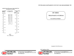
User’s Manual
Model DRC-7/-70
Digital Cryogenic Thermometer
Model DRC=?CMOC
Digital Cryogenic Controller
Obsolete Notice:
This manual describes an obsolete Lake Shore product. This manual is a copy from our
archives and may not exactly match your instrument. Lake Shore assumes no responsibility for
this manual matching your exact hardware revision or operational procedures. Lake Shore is
not responsible for any repairs made to the instrument based on information from this manual.
Lake Shore Cryotronics, Inc.
575 McCorkle Blvd.
Westerville, Ohio 43082-8888 USA
E-Mail Addresses:
[email protected]
[email protected]
Visit Our Website:
www.lakeshore.com
Fax: (614) 891-1392
Telephone: (614) 891-2243
Methods and apparatus disclosed and described herein have been developed solely on company funds of Lake Shore Cryotronics, Inc.
No government or other contractual support or relationship whatsoever has existed which in any way affects or mitigates proprietary
rights of Lake Shore Cryotronics, Inc. in these developments. Methods and apparatus disclosed herein may be subject to U.S.Patents
existing or applied for. Lake Shore Cryotronics, Inc. reserves the right to add, improve, modify, or withdraw functions, design
modifications, or products at any time without notice. Lake Shore shall not be liable for errors contained herein or for incidental or
consequential damages in connection with furnishing, performance, or use of this material.
Obsolete Manual
1975
Table of Contents
Section
I. General Information
1.1
Introduction
1.2
Description-General
1.3
Description-Specific
1.3.1 Model DRC-7
1.3.2 Model DRC-7C
1.3.3 Model DRC-70
1.3.4 Model DRC-70C
1.4
General Specifications
1.5
Accessory Equipment and Custom Options
II. Installation
2.1
Introduction
2.2
Initial Inspection
2.3
Power and Grounding Requirements
2.4
Installation
2.5
Repackaging for Shipment
III. Operating Instructions
3.1
Introduction
3.2
Controls, Indicators and Connectors
3.3
Initial Checks
3.4
Temperature Readout/Control
3.4.1 Model DRC-7
3.4.2 Model DRC-7C
3.4.3 Model DRC-70
3.4.4 Model DRC-70C
3.5
Customer Calibration
3.5.1 Model DRC-7
(A)
Ten Microamp Sensor Current Adjustment
(B) Calibration of Instrument Between
0-300 K
3.5.2 Models DRC-7C, DRC-70 and DRC-70C
Page
1
1
1
2
2
2
2
3
5
6
6
6
8
8
9
9
12
12
12
13
14
16
17
17
17
18
Section
IV.
Theory of Operation
4.1
Introduction
4.2
General Description
4.3
Detailed Description
4.3.1 Power Supply and System Common
4 . 3 . 2 Two Wise Input
4 . 3 . 3 Four Wire Input
4 . 3 . 4 Linearizer
4 . 3 . 5 Comparators and Voltage References
4 . 3 . 6 Amplifier-Stage I
lifier-Stage II
ut Stage and Digital Display
4.4
Temperature Controller
4 . 4 . 1 Model DRC-7C
4 . 4 . 2 Model DRC-70C
ce and Troubleshooting
Introduction
Test Equipment and Accessories
5.3
General Remarks
5.4
Operational Checks
5.5
Nomimal Operating Voltages and Gains
5.5.1 I n i t i a l Adjustments
5 . 5 . 2 Final Adjustments
5.6
Alignment of Controller Section
5.6.1 model DRC-7C
5.6.2 Model DRC-70C
5.7
Troubleshooting Panel Meter
5.8
Circuit Board Removal
5.9
Panel Meter Removal
5.10 Parts List, Printed Circuit Board Component
Locator, and Schematic
5.1
5.2
VI. Appendixes
Page
19
19
19
19
20
20
20
21
21
22
22
22
23
23
27
27
28
29
30
30
31
32
32
32
32
33
33
34
Table of I I l u s t r a t i o n s
Reference Description
Mode1 DRC-70 D i g i t a l Cryogenic Thermometer
Sensor and Heater Cables
Entry Number C o r r e l a t i o n
Rear Panel
Front Panel
P i n Designation for Model DRC-7
BCD P i n Designation f o r Models DRC-7C,
DRC-70, DRC-70C
Figure 4 . 1 Timing Diagram for TS Greater Than TD
Figure 4 . 2 Timing Diagram for TS Less Than TD
Figure 5.1 C i r c u i t Schematic Diagram-Models DRC-7
and DRC-7C TEMPERATURE INDICATOR SECTION
Figure 5.2 C i r c u i t Schematic Diagram-Models DRC-70
and DRC-70C TEMPERATURE INDICATOR SECTION
Figure 5 . 3 C i r c u i t Schematic Diagram-Model DRC-7C
TEMPERATURE CONTROLLER SECTION
Figure 5.4 Circuit Schematic Diagram-Model DRC-70C
TEMPERATURE CONTROLLER SECTION
Figure 5.5 P r i n t e d C i r c u i t Board Components Locator
Table 6.1
DRC-7 S e r i e s Standard S i l i c o n Diode
Table 4-400 K
Figure 1.1
Figure 2.1
Table 3.1
Figure 3.1
Figure 3.2
Table 3 . 2
Table 3.3
Page
v
7
9
10
11
12
15
24
25
39
40
41
42
43
45
TY
Lake Shore C r y o t r o n i c s , Inc. w a r r a n t s each i n s t r u ment o f i t s own manufacture t o be f r e e from d e f e c t s
i n material and workmanship. O b l i g a t i o n s under t h i s
Warranty s h a l l be l i m i t e d t o r e p l a c i n g , r e p a i r i n g
o r g i v i n g c r e d i t f o r t h e purchase p r i c e , a t o u r opt i o n , o f any instrument r e t u r n e d , shipment p r e p a i d ,
t o o u r f a c t o r y f o r t h a t purpose w i t h i n ONE y e a r o f
d e l i v e r y t o t h e o r i g i n a l p u r c h a s e r , provided p r i o r
a u t h o r i z a t i o n f o r such r e t u r n has been g i v e n by an
a u t h o r i z e d r e p r e s e n t a t i v e o f Lake Shore C r y o t r o n i c s ,
Inc.
This Warranty s h a l l n o t apply t o any i n s t r u m e n t ,
which o u r i n s p e c t i o n s h a l l d i s c l o s e t o o u r s a t i s f a c t i o n , t o have become d e f e c t i v e o r unworkable due
t o abuse, mishandling, misuse, a c c i d e n t , a l t e r a t i o n ,
negligence, improper i n s t a l l a t i o n , o r o t h e r causes
beyond o u r c o n t r o l . This Warranty likewise s h a l l
n o t apply t o any instrument o r component n o t manu f a c t u r e d by o t h e r s and i n c l u d e d i n Lake Shore C r y o t r o n i c s , Inc. equipment; t h e o r i g i n a l m a n u f a c t u r e r ' s
warranty i s extended t o Lake Shore C r y o t r o n i c s , Inc.
customers.
Lake Shore Cryotronics reserves t h e r i g h t t o make
changes i n design a t any time without i n c u r r i n g any
o b l i g a t i o n t o i n s t a l l same on u n i t s p r e v i o u s l y purchased.
THERE ARE NO WARRANTIES WHICH EXTEND BEYOND THE DESCRIPTION ON THE FACE HEREOF. THIS WARRANTY I S I N LIEU
OF, AND EXCLUDES ANY AND ALL OTHER WARRANTIES OR REPRESENTATIONS, EXPRESSED, IMPLIED OR STATUTORY, I N CLUDING MERCHANTABILITY AND FITNESS, AS WELL AS ANY
AND ALL OTHER OBLIGATIONS OR LIABILITIES OF LAKE SHORE
CRYOTRONICS, I N C . , I N C L U D I N G , BUT NOT LIMITED TO,
SPECIAL OR CONSEQUENTIAL DAMAGES. NO PERSON, FIRM OR
CORPORATION IS AUTHORIZED TO ASSUME FOR LAKE SHORE
CRYOTRONICS, I N C . ANY ADDITIONAL OBLIGATION OR LIABILITY NOT EXPRESSLY PROVIDED FOR HEREIN EXCEPT I N
WRITING DULY EXECUTED BY AN OFFICER OF LAKE SHORE
CRYOTRONICS, INC.
SECTION I
General Information
1.1
Introduction
This s e c t i o n c o n t a i n s a d e s c r i p t i o n f o r t h e DRC-7 s e r i e s
d i g i t a l temperature r e a d o u t / c o n t r o l l e r instruments which i n c l u d e t h e
Models DRC-7, DRC-7C, DRC-70, and DRC-70C f o r use with t h e Model
DT-500-DRC standard s i l i c o n diode s e n s o r .
1.2
Description-General
The s e r i e s DRC-7 i s a completely s e l f - c o n t a i n e d u n i t providing
t h e c a p a b i l i t y o f both d i r e c t d i g i t a l readout i n k e l v i n temperature u n i t s
and temperature c o n t r o l (DRC-7C and DRC-70C) by d i r e c t d i g i t a l comparison
t o t h e displayed temperature.
The u s e f u l range o f o p e r a t i o n i s 1 t o 400 K u t i l i z i n g t h e s t a n d a r d
DT-500-DRC sensor which has been pre-selected to provide uniform
c h a r a c t e r i s t i c s . P r e - s e l e c t i o n allows t h e s e r i e s DRC-7 t o be used with
s t a n d a r d s e n s o r s without adjustment of any kind. Since t h e standard s e n s o r s
a r e completely interchangeable, t h e s e r i e s DRC-7 may be used t o read o u t
any number o f s e n s o r s w i t h equal accuracy when s e l e c t e d through an
a p p r o p r i a t e e x t e r n a l switch o r m u l t i p l e x e r .
The s e r i e s DRC-7 u n i t s c o n t a i n an i n t e r n a l c o n s t a n t c u r r e n t source
which i s p r e s e t a t t h e f a c t o r y f o r 10 microamps.
As a s t a n d a r d f e a t u r e , a l l u n i t s a r e equipped w i t h a r e c o r d e r o u t p u t
providing 0-4 v o l t s i n increments o f 10 m i l l i v o l t s p e r degree with a
l i n e a r i t y e r r o r o f 0.5 K (DRC-7 and DRC-7C) and 0 . 3 K (DRC-70 and DRC-70C).
Both t h e DRC-7C and DRC-70C r e a d o u t / c o n t r o l l e r u n i t s have an
a d j u s t a b l e f i n e t u n i n g c o n t r o l f o r peak output power adjustment. The f i n e
t u n i n g c o n t r o l i s continuously a d j u s t a b l e t o allow i n f i n i t e r e s o l u t i o n
and minimizing o f t h e overshoot value.
1.3
Description-Specific
The following provides a d e s c r i p t i o n f o r each s p e c i f i c instruments
i n t h e DRC-7 s e r i e s d i g i t a l cryogenic thermometers and c o n t r o l l e r s .
1.3.1
Model DRC-7
The Model DRC-7 provides d i r e c t temperature readout i n k e l v i n
temperature u n i t s with 1 degree r e s o l u t i o n . The e r r o r of l i n e a r i z a t i o n
(conformity) is f a c t o r y set a t 0 . 5 degrees.
1.3.2
Model DRC-7C
The Model DRC-7C combines t h e e l e c t r o n i c s contained i n t h e
Model DRC-7 w i t h a time p r o p o r t i o n a l t h y r i s t o r temperature c o n t r o l l e r .
The c o n t r o l p o r t i o n i s a c t u a t e d by an i n t e r n a l d i g i t a l comparison o f
t h e BCD output t o a d i g i t a l thumbwheel s e t p o i n t switch. The BCD
comparison s i g n a l provides an e r r o r value ( e q u i v a l e n t t o t h e temperature
d e v i a t i o n ) t o a time p r o p o r t i o n a l t h y r i s t o r c o n t r o l c i r c u i t . The
t h y r i s t o r c i r c u i t c o n t r o l s t h e ON time of t h e powered output a v a i l a b l e
from a continuously a d j u s t a b l e v a r i a c with an a d j u s t a b l e power output
o f 0 t o 50 watts.
1.3.3
Model DRC-70
The Model DRC-70, l i k e t h e DRC-7, provides temperature readout
only. However, t h e r e s o l u t i o n has been improved t o 0.1 degree and t h e
conformity e r r o r has been reduced t o 0 . 3 degrees. Both t h e Models DRC-7
and DRC-70 have a s t a n d a r d analog output, t o compliment t h e d i g i t a l display,
p r o v i d i n g a 0-4 v o l t output w i t h a s l o p e o f 10 m i l l i v o l t s / d e g r e e with
t h e i r respective linearity error.
1.3.4
Model DRC-70C
The Model DRC-70C, as t h e DRC-7C, provides both temperature readout
and c o n t r o l over t h e useable range of 1 t o 400 K.
The DRC-70C combines t h e DRC-70 with a r e v o l u t i o n a r y new d i g i t a l
p r o p o r t i o n a l t h y r i s t o r c o n t r o l u n i t having an i n t e r n a l f a c t o r y s e t
bandwidth o f 0.5 k e l v i n . The d i g i t a l p r o p o r t i o n c o n t r o l provides f o r
maximum agreement between t h e s e t p o i n t temperature and t h e a c t u a l
temperature. A f i n e t u n i n g c o n t r o l i s provided on t h e f r o n t panel which
allows t h e maximum peak v o l t a g e t o be a d j u s t e d between 0 and 50 v o l t s rms.
The bandwidth is f i x e d about t h e s e t p o i n t value and i s equal t o
±0.5 K. Operation w i t h i n t h e bandwidth zone allows t h e c o n t r o l l e r t o work
i n a p r o p o r t i o n a l mode. The p r o p o r t i o n a l mode o p e r a t i o n i s d e t e c t a b l e
by a p u l s a t i n g or b l i n k i n g h e a t e r power ON l i g h t . Operation below t h e
p r o p o r t i o n a l zone allows t h e c o n t r o l l e r to work i n a continuously ON
condition.
1.4
General S p e c i f i c a t i o n s
The following s p e c i f i c a t i o n s f o r t h e DRC-7 s e r i e s a r e a p p l i c a b l e
when used w i t h t h e s t a n d a r d DT-500-DRC temperature s e n s o r .
General :
Temperature Range
1 t o 400 K
Sensing Material
S i 1icon (Mode 1 DT- 500-DRC)
Sensor E x c i t a t i o n
10 microamps
Sensor Current Regulation
±. 1%
Sensor Input Connection
2 , 3 , o r 4 wire constant c u r r e n t
I n p u t Resistance
Greater than 100 megohms
Is o l a t i on
300V
Operating Environment
10-45°C
Normal Mode Rejection
50 db min. a t 60 Hz and up
Common Mode Reject i o n
120 db a t 60 Hz and above
Power Requirements
115 o r 230* VAC
±10%, 50/60 Hz
Dimensions
8.9 cm (3.5") high x
20.3 cm (8") wide x
30.5 cm (12") deep
VA1,3,
60 VA2,4
Power Consumption
15
C i r c u i t Design
Solid S t a t e Electronics
Weight
3.6 Kg (8 pounds)1,3, 5.4 Kg
(12 pounds)2,4
*For 230 VAC, add (-K) t o model number; i . e . DRC-70-K
1-Model DRC-7 only
2-Model DRC-7C only
3-Model DRC-70 only
4-Model DRC-70C only
Temperature Readout:
Res o lu t i on :
Digital
Analog
Conformity t o LSCI Standard
DRC-7 S i l i c o n Diode Table
1 k e l v i n 1 , 2 , 0.1 k e l v i n 3,4
B e t t e r than 0.1 k l v i n ( a l l u n i t s )
0.5 K (4-400 K) 1,2
0.3 K (4-400 K)3,4
Maximum Sensor Power D i s s i p a t i o n
25 microwatts a t 4 . 2 K
Maximum D i g i t i z i n g Error
(8 hours a t 25°C)
0.5 K
Temperature Co e f f i c ient Error
0.06
Repeat a b i li t y
1 k e l v i n 1 , 2 , 0.1 k e l v i n 3,4
outputs :
Analog
Digital (optional]
K/°C
10 mV/K at 1 K o u t p u t impedance.
Tracking t o d i g i t a l d i s p l a y of
0.3 K
TTL compatible (non-i s o l a t e d )
Display
3 d i g i t s , 1 4 mm (0.55")
7 segment non -b l i n k i n g
high,
Response Time
2 seconds t o r a t e d accuracy
Temperature Control :
S e t Point
D i g i t a l thumbwheel s e l e c t i o n
d i r e c t l y i n k e l v i n temperature
units
Con t r o l lab i l it y
0.5 K 2 , 0.3 K with a
p r o p e r l y designed system
Repeatability
1 kelvin',
S e tt ab i lit y
1 k e l v i n 2 , 0.1 k e l v i n 4
Heater Output
Standard 0-50 watts,
0-1 A, 0-50 VAC
Control Mode
Time p r o p o r t i o n a l t h y r i s t o r with
contin ously adjustable variac
output
Isolated d i g i t a l proportional
with continuo s l y a d j u s t a b l e
v a r i a c output
4
0.1 K4
2
4
1.5
Accessory Equipment and Custom Options Available
The following accessory equipment and custom options are
available from the factory.
SECTION II
I n s t al la t i on
2.1
Introduction
This s e c t i o n c o n t a i n s information and i n s t r u c t i o n s necessary for
t h e i n s t a l l a t i o n and s h i p p i n g o f t h e s e r i e s DRC-7 D i g i t a l Readout/Controller.
Included a r e i n s p e c t i o n i n s t r u c t i o n s , power and grounding requirements,
i n s t a l l a t i o n information, and i n s t r u c t i o n s f o r repackaging f o r shipment.
2.2
I n i t i a l Inspection
This instrument was e l e c t r o n i c a l l y and mechanically inspected p r i o r
t o shipment. I t should be f r e e from mechanical damages and i n p e r f e c t
working o r d e r upon r e c e i p t . To confirm t h i s , t h e instrument should be
i n s p e c t e d v i s u a l l y f o r obvious damage upon r e c e i p t and t e s t e d e l e c t r o n i c a l l y
by use t o d e t e c t concealed damage. A l l p a r t s should be i n v e n t o r i e d
b e f o r e d i s c a r d i n g any s h i p p i n g m a t e r i a l . I f t h e r e i s damage t o t h e
instrument i n t r a n s i t , be s u r e t o f i l e a p p r o p r i a t e claims w i t h t h e c a r r i e r ,
and/or i n s u r a n c e company. Please a d v i s e t h e company o f such f i l i n g s . I n
c a s e of p a r t s s h o r t a g e s , p l e a s e a d v i s e company. The s t a n d a r d Lake Shore
Cryotronics warranty i s given on page ii.
2.3
Power and Grounding Requirements
To p r o t e c t o p e r a t i n g personnel, t h e National E l e c t r i c a l
Manufacturers' Association (NEMA) recommends and some l o c a l codes r e q u i r e
instruments t o be grounded. This instrument i s equipped with a t h r e e conductor power c a b l e which, when plugged i n t o an a p p r o p r i a t e r e c e p t a c l e ,
grounds t h e instrument.
The s t a n d a r d u n i t i s s e t f o r 115 VAC ±10%, 50/60 H e r t z o p e r a t i o n
w i t h t h e designated (-K) u n i t s s e t for 230 VAC ±10, 50/60 Hertz. The
s t a n d a r d 115 VAC u n i t may b e converted t o 230 VAC by r e q u e s t i n g t h e
conversion procedure from t h e company.
2.4
Installation
The recommended c a b l e diagrams f o r t h e s e n s o r diode and h e a t e r
element a r e given i n Fig. 2.1 ( a ) . The use o f a f o u r wire diode
connection is h i g h l y recommended t o avoid i n t r o d u c i n g lead I R drops i n
t h e v o l t a g e s e n s i n g p a i r . The i n d i c a t e d s h i e l d i n g connections a r e t h e
recommended s t a n d a r d p r a c t i c e t o avoid ground loops. For l e s s c r i t i c a l
a p p l i c a t i o n s , t h e wiring scheme i n F i g . 2 . 1 (b) and (c) may be used.
The h e a t i n g element should be f l o a t e d t o preclude t h e p o s s i b i l i t y
o f any o f t h e h e a t e r c u r r e n t b e i n g conducted i n t o t h e diode sensor.
E l e c t r i c a l feedback, i n a d d i t i o n t o t h e d e s i r e d thermal feedback, may
cause o s c i l l a t i o n s and c e r t a i n l y erroneous temperature readings.
2.5
Repackaging f o r Shipment
Before r e t u r n i n g an instrument t o t h e f a c t o r y f o r r e p a i r , p l e a s e
d i s c u s s t h e malfunction w i t h a f a c t o r y r e p r e s e n t a t i v e . He may be a b l e t o
suggest s e v e r a l f i e l d tests which w i l l p r e c l u d e r e t u r n i n g a s a t i s f a c t o r y
instrument t o t h e f a c t o r y when t h e malfunction i s elsewhere. If it i s
i n d i c a t e d t h a t t h e f a u l t i s i n t h e instrument a f t e r t h e s e t e s t s , t h e
r e p r e s e n t a t i v e w i l l send s h i p p i n g i n s t r u c t i o n s and l a b e l s f o r r e t u r n i n g i t .
When r e t u r n i n g an instrument, p l e a s e a t t a c h a t a g s e c u r e l y t o t h e
instrument i t s e l f (not on t h e s h i p p i n g c a r t o n ) c l e a r l y s t a t i n g :
(1)
Owner and address
(2)
Instrument Model and S e r i a l Number
(3)
Malfunction symptoms
(4) Description o f e x t e r n a l connections and c r y o s t a t s .
I f t h e o r i g i n a l c a r t o n i s a v a i l a b l e , repack t h e instrument i n a
p l a s t i c bag, p l a c e i n c a r t o n using o r i g i n a l styrafoam popcorn t o p r o t e c t
p r o t r u d i n g c o n t r o l s , and c l o s e c a r t o n . Seal l i d w i t h paper or nylon
t a p e . A f f i x mailing l a b e l s and “FRAGILE" warnings.
I f t h e o r i g i n a l c a r t o n i s n o t a v a i l a b l e , wrap t h e instrument i n
p r o t e c t i v e p l a s t i c wrapping m a t e r i a l b e f o r e p l a c i n g i n an i n n e r c o n t a i n e r .
P l a c e shock absorbing material around a l l s i d e s of t h e instrument t o prevent
damage eo p r o t r u d i n g c o n t r o l s . Place t h e i n n e r c o n t a i n e r i n a second
heavy c a r t o n and s e a l with t a p e . Affix mailing l a b e l s and "FRAGILE"
warnings.
SECTION III
Operating I n s t r u c t i o n s
Introduction
3.1
This s e c t i o n c o n t a i n s a d e s c r i p t i o n o f t h e o p e r a t i n g c o n t r o l s
and t h e i r adjustment under normal o p e r a t i n g c o n d i t i o n s . These i n s t r u c t i o n s
a r e p r e d i c a t e d upon t h e instrument having been i n s t a l l e d as o u t l i n e d i n
S e c t i o n II. The diode p o l a r i t y as shown i n Fig. 2 . 1 (a) i n p a r t i c u l a r
must be c o r r e c t .
C o n t r o l s , I n d i c a t o r s and Connectors
3.2
The o p e r a t i n g c o n t r o l s , i n d i c a t o r s and connectors on t h e i n s t r u m e n t ' s
f r o n t and r e a r p a n e l s a r e shown i n Figures 3.1 and 3.2. The numbers with
l e a d e r s t o v a r i o u s c o n t r o l s i n t h e f i g u r e s a r e keyed t o t h e e n t r i e s i n
Table 3.1.
Table 3.1
NO. KEY
-
Entry Number C o r r e l a t i o n
NAME
FUNCTION
1
Heater
Heater element t e r m i n a l s
2
Analog (Hi
3
Input
Sensor i n p u t l e a d t e r m i n a l s ( p l u s I ,
p l u s V, minus V, and minus I )
4
NO LABEL
A.C.
5
NO LABEL
D i g i t a l temperature d i s p l a y l o c a t e d
behind f i l t e r panel. Maximum range
1-400 K.
6
NO LABEL
D i g i t a l s e t p o i n t switch. S e l e c t s
d e s i r e d temperature t o be c o n t r o l l e d t o
d i r e c t l y i n k e l v i n u n i t s . Adjustable
from 2 t o 399 K.
& Lo)
Recorder output
l i n e cord
NO. KEY
NAME
FUNCTION
7
NO LABEL
Fine t u n i n g power c o n t r o l . Adjusts
t h e maximum power a v a i l a b l e from
0-50 VRMS. I n f i n i t e r e s o l u t i o n through
t h e use of a v a r i a c c o n t r o l .
8
PWR
A.C.
9
NO LABEL
Heater ON l i g h t i n d i c a t e s power i s
app 1i e d t o h e a t e r load
BCD
BCD output ( o p t i o n a l )
10
3.3
l i n e switch (ON/OFF)
I n i t i a l Checks
I n i t i a l checks, c a l i b r a t i o n checks, and s e r v i c i n g procedures are
described i n S e c t i o n V, Maintenance.
3.4
Temperature Readout/Control
3.4.1
Model DRC-7
The d i g i t a l panel meter has p r o v i s i o n s t o accept a connector a t t h e
r e a r o f t h e case. A connector package i s s u p p l i e d which c o n s i s t s of a
connector ELCO No. 00-6007-030-980-002 and two screws No. 4-40 thd by
½ inch long binding head.
Table 3.2 provides t h e necessary p i n d e s i g n a t i o n f o r i n p u t and
o u t p u t signals.
Table 3 . 2
PIN NO.
1.
2.
3.
4.
5.
6.
7.
8.
9.
10.
-
Pin Designation f o r Model DRC-7
FUNCTION
+4.8 v o l t s
Analog (+)
P r i n t Command
Polarity
BCD 8
BCD 2
BCD 80
BCD 20
Sensor Input (+)
Analog (-) , S i g n a l
Ground
P I N NO.
FUNCTION
A.
B.
C.
D.
E.
F.
H.
J.
K.
+9 v o l t s
Current Test (+)
Overrange
Hold
BCD 1
BCD 4
BCD 10
BCD 40
BCD 100
L.
N/C
B I N NO.
11.
1 2.
13.
14.
15 .
FUNCTION
BCD 400
BCD 200
Current Test (-)
Sensor Input (-)
115/230 VAC Line 1
P I N NO.
M.
N.
P.
R.
S.
FUNCTION
T r i p Point
D i g i t a l Gnd, BCD Gnd
N/C
Shield
115/230 VAC Line 2
The s e n s o r i s connected t o t h e instrument v i a p i n s #9 and #14,
The i n t e r n a l c u r r e n t source can be checked by p l a c i n g a 100 K ohm
±.01% r e s i s t o r between p i n s 13 and B and measuring t h e v o l t a g e drop with a
v o l t m e t e r having an accuracy of 0.01% error.
For t h o s e u n i t s having t h e o p t i o n a l BCD output, a binary-codeddecimal (BCD) i s provided as l i s t e d i n Table 3.2. The decade c o u n t e r s
provide a 1-2-4-8 code u s i n g p o s i t i v e l o g i c w i t h standard TTL l e v e l s of
0 . 4 v o l t s and 2 . 4 v o l t s f o r t h e 0 and l state, r e s p e c t i v e l y . The d r i v e
i s s u f f i c i e n t t o s i n k t w o standard loads, 3.2 mA, i n t h e low state.
For a d d i t i o n a l usage, a switch o r TTL m i c r o c i r c u i t connected t o t h e
h o l d terminal (Pin D) can be used t o keep t h e v o l t a g e level low and defeat
the synchronizing signal applied to the synchronizing divider. This will
prevent the generation of a r e s e t pulse.
3.4.2
Model DRC-7C
The s e n s o r and h e a t e r should be i n s t a l l e d following t h e suggestions
l i s t e d i n t h e " I n s t a l l a t i o n and Application Notes f o r Cryogenic Sensors”
brochure i n S e c t i o n V I .
Connect t h e s e n s o r and h e a t e r t o t h e instrument following t h e
diagrams i n Fig. 2.1.
Rotate t h e f i n e tuning power c o n t r o l (Key No. 7) f u l l c o u n t e r clockwise t o minimum power output. Adjust t h e d i g i t a l thumbwheel switch
(Key No. 6) t o 001.
Turn t h e power switch (Key No. 8) t o ON and observe t h a t t h e
d i s p l a y (Key No. 5) shows t h e proper temperature r e l a t i v e t o t h e sample
temperature.
I f t h e d i s p l a y r e a d s -1800, 1090, o r blanks, the diode is connected
backwards.
The h e a t e r ON l i g h t (Key No. 9) should be o f f .
Adjust t h e set p o i n t (Key No. 6) t o one degree below t h e value
b e i n g d i s p l a y e d (Key NO. 5) and observe t h a t t h e h e a t e r power l i g h t
(Key No. 9) remains o f f . Advance t h e set p o i n t 2 K and observe t h a t t h e
h e a t e r power l i g h t t u r n s ON. Return t h e set p o i n t t o i t s o r i g i n a l v a l u e
and check t h a t t h e h e a t e r power l i g h t s h u t s OFF. I f l i g h t does n o t s h u t
o f f , check to see i f d i s p l a y i s i n d i c a t i n g a d i f f e r e n t temperature.
The h e a t e r power l i g h t w i l l remain ON as long as t h e set p o i n t is
less t h a n t h e d i s p l a y by a t least 1 K .
I n c r e a s e t h e set p o i n t switch u n t i l t h e d e s i r e d value i s s e t . I f
t h e temperature set p o i n t i s larger than t h e temperature being displayed,
t h e h e a t e r ON l i g h t w i l l i l l u m i n a t e i n d i c a t i n g power is being a p p l i e d t o
t h e h e a t e r . Observe t h e d i s p l a y and if t h e temperature being displayed
does n o t show s i g n s o f h e a t i n g , then i n c r e a s e t h e maximum power o u t by
r o t a t i n g , clockwise, t h e f i n e t u n i n g c o n t r o l knob (Key No. 7 ) . The knob
should be r o t a t e d i n ¼ t u r n increments u n t i l t h e p r o p e r rate o f h e a t i n g
is observed on t h e temperature d i s p l a y . I f t h e i n c r e a s e i n temperature
is slow o r t h e temperature does n o t i n c r e a s e , (and i s s t i l l below t h e
temperature set p o i n t ) , r o t a t e t h e f i n e t u n i n g knob a n o t h e r ¼ t u r n . Repeat
above procedure u n t i l t h e d e s i r e d rate o r temperature i s achieved. When
t h e readout is equal t o o r greater than t h e temperature s e t p o i n t , t h e
heater ON l i g h t will switch OFF.
The maximum c o n t r o l l a b i l i t y w i l l be achieved with t h e minimum v a l u e
of amplitude p u l s e h e i g h t a p p l i e d t o t h e h e a t e r ( c o n t r o l l e d by t h e f i n e
t u n i n g knob (Key No. 7 ) . This c o n d i t i o n can be d e t e c t e d by observing a
continuous switching between ON and OFF of t h e h e a t e r ON l i g h t .
3.4.3
Model DRC-70
The s e n s o r should be connected t o both t h e sample area and instrument
following t h e suggestions noted i n S e c t i o n 3.4.2.
The s e n s o r and readout d i s p l a y should follow Table 6.1 which
i l l u s t r a t e s t y p i c a l values expected of t h e s t a n d a r d DT-500-DRC s e n s o r s . If
t h e instrument o r s e n s o r does n o t a g r e e with values l i s t e d i n t h e t a b l e ,
c o n s u l t s e c t i o n s on i n s t a l l a t i o n and/or s e c t i o n on t r o u b l e s h o o t i n g t o
determine cause and c u r e o f malfunction.
For t h o s e u n i t s equipped with BGD o u t p u t , t h e following Table 3 . 3
i l l u s t r a t e s t h e f u n c t i o n of each p i n d e s i g n a t i o n .
Table 3.3 - BCD Pin Designation for
Models DRC-7C, DRC-70, and DRC-70C
PIN NO.
FUNCTION
1
N/ A
2
N/A
3
Print command
4
Po larity
5
BCD 8
6
BCD 2
7
BCD 80
8
BCD 20
9
BCD 800
10
N/A
11
BCD 400
12
BCD 200
13
N/A
14
BCD 1000
15
Hold
16
BCD 1
17
BCD 4
18
BCD 10
19
BCD 40
20
BCD 100
21
Digital GND, BCD, GND
22
BCD 2000
23
N/A
24
Overload
25
Shift
All terminations for above signals are located at t h e BCD connector
(Key No. 10) type 117-10250 by Amphenol.
3.4.4 Model DRC-70C
Connect t h e s e n s o r following t h e procedure o u t l i n e d i n Section 3.4.2.
Before applying power, t h e f i n e t u n i n g c o n t r o l (Key No. 7) should
be r o t a t e d f u l l counterclockwise to minimum power output and t h e set p o i n t
switch (Key No. 6) t o 002.0 K. Note! If 000.0 K i s set i n t h e thumbwheel
switch, t h e u n i t w i l l apply f u l l power t o t h e h e a t e r . Observe t h e
temperature d i s p l a y (Key No. 5) and i f it i s greater than t h e set p o i n t by
0.5 K (Key No. 6 ) , t h e h e a t e r ON l i g h t (Key No. 9) should b e o f f
i l l u s t r a t i n g zero power b e i n g a p p l i e d t o h e a t e r load.
Adjust t h e set p o i n t t o a v a l u e equal t o 0.5 K less t h a n
being displayed and observe t h a t t h e power ON l i g h t j u s t begins
i l l u m i n a t e . Adjust i n 0.1 K increments, t h e s e t point, towards
being displayed and observe t h e power ON l i g h t begins t o appear
f r e q u e n t l y . When t h e set p o i n t v a l u e e q u a l s t h e d i s p l a y value,
ON l i g h t should be on 50% of t h e time. Note! This test should
performed with a displayed v a l u e less than 150 K.
t h e value
to
t h e value
more
t h e power
be
Continue t o i n c r e a s e set p o i n t i n 0.1 K increments and note t h a t
t h e power ON l i g h t continues t o i n c r e a s e i n frequency. With t h e set p o i n t
equal to 0.5 K plus the value on display, the power ON l i g h t will be on
continuously (100% o f t h e time) . I f t h e above observances are met, t h e
u n i t i s f u n c t i o n i n g p r o p e r l y . If not, see s e c t i o n s on i n s t a l l a t i o n and
s e c t i o n on t r o u b l e s h o o t i n g f o r c o r r e c t i n g m a l f u n c t i o n
With t h e u n i t f u n c t i o n i n g p r o p e r l y , a d j u s t set p o i n t switch to t h e
d e s i r e d temperature value.
I n c r e a s e t h e maximum output power by r o t a t i n g t h e f i n e t u n i n g
c o n t r o l (Key No. 7) ¼ t u r n and observe t h e rate o f h e a t i n g i n d i c a t e d by
t h e readout d i s p l a y ' s r a t e of change. If t h e i n c r e a s e i n temperature is
slow or t h e temperature does n o t i n c r e a s e , (and is s t i l l below t h e temperr o t a t e t h e f i n e t u n i n g knob another & t u r n . Repeat t h e
a t u r e set p o i n t ) ,
above procedure until t h e d e s i r e d rate of i n c r e a s e o r t h e set temperature
i s achieved, When t h e readout d i s p l a y is w i t h i n 0.5 K of t h e temperature
set p o i n t , t h e h e a t e r ON l i g h t (Key No. 9) w i l l begin t o b l i n k
p r o p o r t i o n a l l y to t h e d i f f e r e n c e between t h e set point temperature and
t h e d i s p l a y temperature. I f t h e overshoot d r i v e s t h e temperature 0.5 K
beyond t h e set p o i n t , t h e h e a t e r ON l i g h t w i l l switch o f f .
The maximum c o n t r o l l a b i l i t y w i l l be achieved with minimum v a l u e of
amplitude p u l s e h e i g h t a p p l i e d t o t h e h e a t e r ( c o n t r o l l e d by t h e f i n e
t u n i n g knob - Key No. 7 ) . This c o n d i t i o n is d e t e c t e d by observing a 50%
p r o p o r t i o n a l duty c y c l e switching between ON and OFF of t h e h e a t e r ON
Bight .
Customer C a l i b r a t i o n
3.5
The procedure o u t l i n e d below i s a p p l i c a b l e to Table 6.1 f o r a l i g n i n g
a l l series DRC-7 instruments.
3.5.1 Model DRC-7*
(A)
Ten Microamp Sensor Current Adjustment
(1)
Remove t h e f r o n t panel cover on t h e meter.
(2)
Turn t h e power ON to t h e instrument and allow about
BO minutes warm up.
(3)
Connect a voltmeter with a 0.01% accuracy and a 100 megohm
minimum r e s i s t a n c e between p i n s B and 13, t h e p o s i t i v e
t e r m i n a l o f t h e voltmeter should be connected t o p i n B.
Connect a 10 uF c a p a c i t o r across p i n s B and 13 i f t h e
connector leads are long.
(4)
Adjust t h e potentiometer marked “1”, l o c a t e d a t t h e back of
t h e instrument u n t i l t h e v o l t m e t e r reads 100.0 m i l l i v o l t s .
(B) Calibration of t h e Instrument Between 0-300 K
(1) Connect a v o l t a g e standard, such as EDC Model MV-100N,
to t h e probe i n p u t t e r m i n a l s and set t h e v a l u e of 2.81586 v o l t s
on t h e v o l t a g e standard.
*Note!
(2)
S e t t h e ZERO a d j u s t potentiometer u n t i l t h e meter d i s p l a y s
000. The ZERO potentiometer is l o c a t e d on t h e f r o n t p a n e l ,
a t t h e r i g h t hand s i d e of d i s p l a y ,
(3)
S e t t h e v o l t a g e s t a n d a r d t o t h e value of 0.37721 v o l t s and
a d j u s t t h e SPAN potentiometer u n t i l t h e meter d i s p l a y s 300.
The SPAN potentiometer i s l o c a t e d to t h e l e f t of t h e d i s p l a y .
(4)
a i s p 1ayed .
(5)
Set the v o l t a g e s t a n d a r d t o t h e value of 1.09471 v o l t s and
a d j u s t t h e potentiometer l a b e l e d "7" until t h e meter d i s p l a y s
035. This potentiometer i s l o c a t e d at t h e back of t h e meter.
(6)
Repeat above s t e p s , if necessary.
Repeat s t e p s 1 through 3 u n t i l t h e r e s p e c t i v e readings are
For DRC-7 u n i t s having a s e r i a l i z e d number g r e a t e r than 2000, use
c a l i b r a t i o n procedure under S e c t i o n 3.5.2.
3.5.2
Models DRC-7C, DRC-70, and DRC-70C
(1)
Connect t h e i n p u t terminals t o a v o l t a g e s t a n d a r d such
as EDN Model MV-100N o r e q u i v a l e n t and a voltmeter ( i n p u t
±199.99 mV, r e s o l u t i o n 10 uV, ±0.05% accuracy and an i n p u t
impedance of not less than 1000 megohms) a c r o s s resistor R80.
The p o s i t i v e terminal of t h e voltmeter should be connected
t o t h e t e s t p o i n t 1 and t h e n e g a t i v e t e r m i n a l t o t e s t
point 2 .
(2)
Turn t h e power on and allow approximately 60 minutes warm up
time .
(3)
Adjust p o t e n t i o m e t e r R79 u n t i l t h e v o l t m e t e r reads 100.0 mV.
(4)
S e t t h e v o l t a g e s t a n d a r d t o 1.9755 v o l t s . Adjust t h e ZERO
potentiometer R34 u n t i l t h e panel meter reads 013.1 (013 f o r
Model BRC-7C) .
(5)
S e t the voltage s t a n d a r d t o 1.1283 v o l t s . Adjust potentiometer
R19 t o a value of 028.0 on t h e panel meter d i s p l a y .
(6)
S e t the voltage standard to 0.9811 volts and adjust;
p o t e n t i o m e t e r R26 t o a value of 077.3 (077 for Model DRC-7C)
on t h e panel meter d i s p l a y .
(7)
S e t t h e v o l t a g e s t a n d a r d t o 0.099 v o l t s and a d j u s t potentiometer
l a b e l e d “FS” (R33) t o a value of 395.2 (395 for Model DRC-7C)
on t h e panel meter.
(8) Repeat above s t e p s , if necessary,
SECTION I V
Theory o f Operation
4.1
Introduction
T h i s s e c t i o n c o n t a i n s t h e t h e o r y of o p e r a t i o n of t h e series DRC-7
D i g i t a l Readout/Controller t o a i d t h e system engineer i n designing a
s t a b l e thermal system. Refer t o Figures 4.1, 4.2, 5.1, 5.2, 5.3, 5.4,
5.5 as an a i d i n t h e following d i s c u s s i o n .
4.2
General Description
"he diode s e n s o r (Model DT-500-DRC) is e x c i t e d by an a d j u s t a b l e
(Rag) c o n s t a n t c u r r e n t source and forms t h e feedback element o f t h e i n p u t
a m p l i f i e r (22). The output o f t h i s a m p l i f i e r i s a v o l t a g e r e f e r r e d t o
t h e system common (TP #10) and is p r o p o r t i o n a l t o t h e v o l t a g e o u t p u t of
t h e sensor.
The amplifier output voltage is compared with a predetermined
v o l t a g e r e f e r e n c e corresponding t o t h e v a r i o u s l i n e a r i z e r segment break
p o i n t s from t h e s t a n d a r d DRC-7 v o l t a g e versus temperature t a b l e . The
a t t e n u a t e d o u t p u t o f t h e i n p u t amplifier is fed i n t o two s t a g e s o f
a m p l i f i e r s (23 and Z5) whose gain is v a r i a b l e as a f u n c t i o n of t h e s e n s o r
temperature, The gain changing networks are switched by means o f analog
switches set t o c l o s e when t h e v o l t a g e output o f t h e s e n s o r a m p l i f i e r (22)
i s equal t o t h e predetermined v o l t a g e r e f e r e n c e corresponding t o each
break p o i n t o f t h e DRC-7 s t a n d a r d t a b l e . The v o l t a g e o u t p u t o f t h e
l i n e a r i z e r i s a l i n e a r f u n c t i o n o f t h e s e n s o r temperature. This output
i s converted t o a l i n e a r i z e d output of 10 mV/K and t h e d i g i t a l voltmeter
r e a d s and d i s p l a y s t h i s o u t p u t .
4.3
Detailed D e s c r i p t i o n
A d e t a i l e d d e s c r i p t i o n o f t h e v o l t a g e temperature conversion i s
o u t l i n e d below .
4.3.1
Power Supply and System Common
The output of transformer (T1) i s r e c t i f i e d and f i l t e r e d t o 22 VDC
by means o f a f u l l wave b r i d g e (CR1-4) and a c a p a c i t o r C24 f i l t e r . "he
l i n e f i l t e r C19, C20, and C25 on t h e power l i n e bypasses t h e high frequency
n o i s e s i g n a l i n t h e power lime. The f i l t e r e d , b u t unregulated, 22 VDC i s
r e g u l a t e d t o 14 VDC by a p r e c i s i o n v o l t a g e r e g u l a t o r (Z24),
The v o l t a g e s a t v a r i o u s p a r t s of t h e c i r c u i t are r e f e r r e d t o t h e
"System Common" which i s t h e o u t p u t o f t h e a m p l i f i e r (27). The common i s
l o c a t e d 7 VDC below t h e p o s i t i v e r e g u l a t e d v o l t a g e . This v o l t a g e can be
a d j u s t e d t o w i t h i n ±0.001 v o l t s w i t h p o t e n t i o m e t e r R71. The a m p l i f i e r s ,
comparators, and t h e analog switches i n t h i s system are o p e r a t e d between
V+ and V- (14 v o l t s ) and t h e networks f o r t h e b i a s and gain c o n t r o l s work
between V+ and common. Therefore, t h e o u t p u t o f a l l a m p l i f i e r s i s r e f e r r e d
t o t h e "System Common".
4.3.2
Two Wire Input
This diode s e n s o r i s s u p p l i e d by a c o n s t a n t c u r r e n t of 10 microamperes which i s a d j u s t a b l e (R79) t o provide t h e c u r r e n t e x c i t a t i o n . The
s e n s o r forms t h e feedback element o f t h e a m p l i f i e r (22). The o f f s e t a d j u s t
p o t e n t i o m e t e r (R89) p r o v i d e s t h e e x a c t v o l t a g e r e q u i r e d by t h e l i n e a r i z e r .
The two-wire i n p u t i s s u b j e c t t o v o l t a g e e r r o r s produced by t h e I R drops
along t h e l e a d wires w i t h 10 microamps flowing.
4.3.3
Four Wire Input
S i n c e t h e s e n s o r forms t h e feedback element o f a m p l i f i e r Z2, t h e
l e a d r e s i s t a n c e w i l l have a n a p p r e c i a b l e e f f e c t on t h e accuracy as noted i n
S e c t i o n 4 . 3 . 2 . This e f f e c t i s reduced by u t i l i z i n g a four-wire i n p u t as
follows. The o u t p u t o f a m p l i f i e r Z2 i s connected t o t h e n e g a t i v e i n p u t of
t h e u n i t y gain a m p l i f i e r Z11. The p o s i t i v e i n p u t o f a m p l i f i e r Z11 i s
r e f e r r e d t o t h e cathode o f t h e s e n s o r through l e a d # 3 ( p i n #11). The
v a r i a t i o n o f t h e o u t p u t o f a m p l i f i e r Z2 due t o t h e l e a d r e s i s t a n c e o f
l e a d #1 ( p i n #9) and l e a d #2 (pin #10) i s equal and o p p o s i t e t o t h e
v a r i a t i o n o f t h e v o l t a g e o f l e a d # 3 ( p i n #11). Due t o t h e e q u a l i t y , t h e y
cancel a t t h e o u t p u t o f t h e a m p l i f i e r Z11 which p r o v i d e s t h e e x a c t v o l t a g e s
(equal t o s e n s o r ) r e q u i r e d by t h e l i n e a r i z e r . For long l e a d r u n s , it i s
suggested t h a t s h i e l d c a b l e s be used t o minimize n o i s e pickup.
4.3.4
Linearizer
The s e r i e s DRC-7 u t i l i z e s s t r a i g h t l i n e segments o v e r t h e range o f
1 t o 400 k e l v i n with break p o i n t s a t 6 K , 1 4 K , 18 K , 23 K , 25 K , 27 K,
30 K , and 80 K. The s l o p e between 18 and 23 K i s t h e l a r g e s t (75.3 mV/K)
and, hence, t h e gain o f t h e l i n e a r i z e r i s t h e lowest between t h e s e p o i n t s .
S i m i l a r l y , t h e l i n e a r i z e r has i t s h i g h e s t gain between 30 and 80 K where
t h e diode has t h e s m a l l e s t s l o p e of 2.66 mV/K.
4.3.5
Comparators and Voltage References
The r e f e r e n c e v o l t a g e s a r e formed i n s t e p s o f ascending o r d e r
corresponding t o t h e v o l t a g e output o f t h e i n p u t a m p l i f i e r a t t h e various
break p o i n t s . A l a d d e r network connected between V+ and common provide
these voltages
.
The r e f e r e n c e v o l t a g e s a r e compared with t h e r e s p e c t i v e output
v o l t a g e s of t h e i n p u t a m p l i f i e r and analog switches SW4 through SW7 a r e
c l o s e d when t h e a m p l i f i e r v o l t a g e i s equal t o t h e r e f e r e n c e v o l t a g e . The
analog switches SW1, SW2, and SW3 a r e s e t t o open when t h e a m p l i f i e r
v o l t a g e exceeds t h e r e f e r e n c e v o l t a g e . This occurs when t h e i n i t i a l gain
o f t h e l i n e a r i z e r i s lower than t h e lowest gain which occurs between 18
and 23 K. Analog switch SW8 opens a t 80 K s i n c e t h e gain over t h e
temperature range 80 t o 400 K i s lower than t h e gain between 30 and 80 K .
Due t o t h e sharp i n c r e a s e i n gain between 27-30 K and 30-80 K , t h e
analog switches should be closed e x a c t l y a t t h e a m p l i f i e r v o l t a g e c o r r e s ponding t o break p o i n t s 27 K and 30 K. The adjustments f o r t h e s e two
break p o i n t s a r e accomplished with potentiometers R99 and R98, r e s p e c t i v e l y .
The high s l o p e below 27 K guarantees t h a t t h e e r r o r r e s u l t i n g from t h e
s e t p o i n t accuracy o f t h i s break p o i n t w i l l n o t have any s i g n i f i c a n t e f f e c t
on t h e o v e r a l l accuracy. The s e t p o i n t accuracy a t t h e break p o i n t f o r
80 K is n o t very c r i t i c a l s i n c e t h e o v e r a l l gain between 80 and 400 K i s
reduced only by 1/28th o f t h e maximum gain.
4.3.6
Amplifier
-
Stage I
The c h a r a c t e r i s t i c s o f t h e Model DT-500-DRC (see s t a n d a r d t a b l e
o f DRC-7) shows t h a t t h e r a t i o o f t h e h i g h e s t gain t o t h e lowest g a i n is
28. Therefore, t o o p e r a t e a m p l i f i e r Z3 w i t h i n i t s l i n e a r r e g i o n , it i s
necessary t o a t t e n u a t e t h e s i g n a l o f t h e i n p u t a m p l i f i e r Z2 t o approximately
1/20 of i t s a c t u a l l e v e l . This s i g n a l is f e d i n t o t h e p o s i t i v e terminal of
u n i t y gain a m p l i f i e r Z3 t o maintain t h e p r o p e r sign, with t h e n e g a t i v e
i n p u t t e r m i n a l following t h e p o s i t i v e i n p u t t e r m i n a l and w i t h t h e d i f f e r e n c e
being only t h e o f f s e t v o l t a g e o f t h e a m p l i f i e r . Therefore, when t h e
comparator c l o s e s t h e analog switch, a r e f e r e n c e v o l t a g e equal t o t h e
v o l t a g e at t h e n e g a t i v e terminal i s switched. A t t h e p o i n t o f switching,
no c u r r e n t flows through Rswitch. For example, i f analog switch SW4 i s
c l o s e d , t h e r e f e r e n c e v o l t a g e V12 i s a p p l i e d and i s e q u i v a l e n t t o t h e
v o l t a g e a t break p o i n t 2 3 K. No c u r r e n t w i l l flow through R10 f o r
break p o i n t 2 3 K p r o v i d i n g a gain o f Z3 e q u i v a l e n t t o t h e gain f o r segment
18 t o 23 K. As t h e i n p u t v o l t a g e i n c r e a s e s , c u r r e n t , p r o p o r t i o n a l t o t h e
i n p u t v o l t a g e , flows through R10 and t h e g a i n o f a m p l i f i e r Z3 i s modified
accordingly
The gain network a t t h e n e g a t i v e i n p u t o f a m p l i f i e r Z3 is
d i v i d e d i n t o 1 / 3 R and 2 / 3 R i n o r d e r t o keep t h e value o f R7 and R4,
r e s p e c t i v e l y , w i t h i n 1.3 megohms. I t i s a l s o necessary t o keep t h e value
o f R20 above 10 K ohms so t h a t t h e r e s i s t a n c e o f t h e analog switch w i l l
be n e g l i g i b l e compared t o R20. A t break p o i n t s 27 K and 30 K , t h e value
of (V18 and V19) and (V25 and V26) should be e x a c t l y equal t o t h e v o l t a g e a t
t h e n e g a t i v e i n p u t t e r m i n a l o f Z3 through a d j u s t a b l e potentiometers R26
and R19.
Since t h e gain between 4 and 6 K i s lower than t h a t between 6 and
1 4 K, r e s i s t o r R35 is switched a c r o s s R49 (feedback r e s i s t o r ) t o provide
t h e lower gain r e q u i r e d .
I n t h e temperature range 18 t o 2 3 K , a l l switches SW1 through SW7
a r e open t o provide t h e p r o p e r s l o p e and gain for conformity t o standard
DRC-7 t a b l e .
4.3.7
Amplifier
-
Stage II
Operation between 80 t o 400 K i s accomplished with t h e break p o i n t
s e t f o r 80 K which t r i g g e r s t h e comparator t o o p e r a t e switch SW8 i n t o an
open s t a t e . The comparator switches when t h e v o l t a g e a t t h e i n p u t t o
Z5 exceeds 0.97405 v o l t s . With t h e gain change i n t h i s s t a g e only 1/28th
o f t h e h i g h e s t gain, any e r r o r introduced by r e s i s t o r R22 and t h e v o l t a g e
o f f s e t i n a m p l i f i e r Z5 w i l l be n e g l i g i b l e .
4.3.8
Output Stage and D i g i t a l Display
The o u t p u t a m p l i f i e r Z5 provides t h e necessary o f f s e t and gain t o
y i e l d an o v e r a l l output o f 4.000 v o l t s corresponding t o 400.0 k e l v i n with
a l i n e a r response o f 10 mV/K as i n d i c a t e d by t h e d i g i t a l voltmeter (DVM)
d i s p 1ay
4.4
Temperature Controller
The f u n c t i o n o f t h e c o n t r o l l e r i s t o apply power t o t h e h e a t e r when
t h e r e a d i n g on t h e d i g i t a l d i s p l a y i s below t h e value s e t by t h e d i g i t a l
s e t p o i n t c o n t r o l switch. The f u l l power condition of t h e h e a t e r i s
i n d i c a t e d by a red l i g h t e m i t t i n g diode (LED), (Key No. 9 ) . The maximum
( f u l l power) h e a t e r v o l t a g e i s continuously a d j u s t a b l e ( v i a f i n e t u n i n g
power c o n t r o l , Key No. 7) between 0 and 50 VAC and can supply a maximum
output c u r r e n t o f 1 amp.
4.4.1
Model DRC-7C
The following d e s c r i p t i o n o f t h e c o n t r o l l e r system r e f e r s t o
Figures 4.1, 4 . 2 , and 5.3.
Assume t h e temperature s e t p o i n t TS is g r e a t e r than t h e temperature
d i s p l a y TD (Fig. 4.1), t h e n t h e BCD output o f t h e counters (214, Z15, and 216)
i s below t h e BCD code generated by t h e thumbwheel switch s e t t i n g . A
comparison i s attempted with Z10, Z18, Z19, and Z20. However, due t o t h e
i n e q u a l i t y , a comparison cannot be made and a l o g i c 1 i s provided which
l a t c h e s Z13 and f u l l power i s a p p l i e d t o t h e h e a t e r and t h e power ON
l i g h t (Key No. 9) i s turned ON i n d i c a t i n g f u l l power f o r a f i x e d number
o f timing c y c l e s determined by updating s i g n a l contained i n t h e d i g i t a l
panel meter.
Assume t h e temperature set p o i n t TS is less than t h e temperature
d i s p l a y TD (Fig. 4 . 2 ) , then t h e BCD output o f t h e counters ( Z 1 4 ,Z15, and 216)
i s g r e a t e r t h a n t h e BCD code generated by t h e thumbwheel switch s e t t i n g .
A comparison i s made u t i l i z i n g comparators Z10, Z18, Z19, and Z20 r e s u l t i n g
i n an equal o r greater than c o n d i t i o n which d r i v e s t h e comparator output
t o a l o g i c s t a t e 0. This c o n d i t i o n i s l a t c h e d with Z13 and remains
l a t c h e d u n t i l a r e s e t occurs. The l a t c h e d c o n d i t i o n w i l l occur f o r both
TS<TD and TS = TD.
To prevent f u l l power from being a p p l i e d d u r i n g t h e r e s e t c y c l e ,
t r a n s i s t o r s Q4 and Q5 are equipped w i t h RC networks (R123, C35 and R 1 3 1 , C30)
f o r a s h o r t time delay.
4.4.2
Model DRC-70C
The d i g i t a l p r o p o r t i o n a l c o n t r o l l e r with f i x e d bandwidth u t i l i z e s
The d i g i t a l p r o p o r t i o n a l c i r c u i t samples t h e
temperature d i s p l a y and temperature s e t p o i n t t o determine t h e magnitude
o f d i f f e r e n c e and adds a p r o p o r t i o n a l l y g r e a t e r number o f signal p u l s e s
t o t h e h e a t e r output c i r c u i t f o r s u c c e s s i v e l y l a r g e r d e v i a t i o n s between
temperature d i s p l a y and temperature set p o i n t .
a new concept f o r c o n t r o l .
The c i r c u i t i s f a c t o r y a d j u s t e d (216) f o r a bandwidth of ±½ K about
t h e temperature s e t p o i n t .
The bandwidth c i r c u i t adds i t s o u t p u t t o t h e i n p u t from t h e BCD
output of t h e temperature d i s p l a y allowing t h e comparators t o s e e an
a r t i f i c i a l value o f real temperature. The bandwidth c i r c u i t adds t h e
a r t i f i c i a l temperature u n i t s t o t h e counter (216) by way of a d d i t i o n a l
counts, with each a d d i t i o n a l count e q u i v a l e n t t o 0.1 degree. The
a r t i f i c i a l temperature i s c o n s t a n t l y a d j u s t i n g f o r changes between actual
temperature and set p o i n t temperature t o a r r i v e a t a c o n t r o l l e d temperature
approximately equal t o t h e d i s p l a y e d temperature.
Assume t h e a r t i f i c i a l temperature (TA) is ½ K (5 counts) above t h e
a c t u a l d i s p l a y temperature TD and t h a t t h e temperature set p o i n t TS is equal
t o TD t h e n as i n S e c t i o n 4.4.1, t h e c o n t r o l c i r c u i t w i l l provide a l o g i c
s t a t e 0 t o prevent power from being a p p l i e d except for a small amount o f
r e s i d u a l power which i n c r e a s e s l i n e a r i t y from 0 K (0 power) t o 400 K
(15%power).
Assume t h e temperature s e t p o i n t (Ts) i s g r e a t e r than t h e temperature
d i s p l a y TD. S i n c e t h e c o u n t e r c i r c u i t i s modified t o count 5 counts (½ K)
above t h e d i s p l a y , t h e d i s p l a y w i l l a c t u a l l y be 5 counts (½ K) below t h e
a r t i f i c i a l temperature TA. When t h e d i s p l a y is 5 counts below t h e
temperature s e t p o i n t s e t t i n g , then t h e l a t c h c i r c u i t Z17 allows t h e
bandwidth c o u n t e r (216) t o r e g i s t e r t h e number o f counts above t h e s e t
point and transfer these t o comparison circuit Z10, Z18, Z19, and Z20. The
comparison number is converted t o a p r o p o r t i o n a l v o l t a g e which d r i v e s a
ramp g e n e r a t o r (222) t o p r o v i d e an a d j u s t a b l e time p e r i o d (R128)
p r o p o r t i o n a l t o t h e count.
The p r o p o r t i o n a l time p e r i o d d r i v e s t r a n s i s t o r s Q3 and Q4 t o provide
power t o t h e h e a t e r .
SECTION V
Maintenance and Trouble Shooting
5.1
Introduction
This s e c t i o n c o n t a i n s i n s t r u c t i o n s f o r maintaining and c a l i b r a t i n g
t h e series DRC-7 instrument, nominal v o l t a g e values and g a i n s , c i r c u i t
schematic diagrams, p r i n t e d c i r c u i t board component diagram, and p a r t s
list.
5.2
Test Equipment and Accessories
The following t e s t equipment i s r e q u i r e d t o perform t h e necessary
ad j us tment s
.
a)
Voltage Standard: E l e c t r o n i c Development Corporation,
Model MV-100N o r equivalent
b)
Voltmeter #1:
-
Input
±9.999 v o l t s
Resolution - 1 mV
Accuracy - ±0.05% Reading, ±0.05% F.S.
Input Impedance - Not l e s s than 100 megohms
Voltmeter # 2 :
Input - ±1.999 v o l t s
Resolution - 1 mV
Accuracy
±0.05% Reading, ±0.05% F.S.
Input Impedance - Not l e s s than 100 megohms
-
Voltmeter # 3 :
Input - ±199.9 mV
Resolution
100 uV
Accuracy - ±0.05% Reading, ±0.05% F.S.
Input Impedance - Not less than 1000 megohms
-
Voltmeter #4:
Input - ±199.99 mV
Resolution - 10 uV
Accuracy - ±0.05% Reading, ±0.05% F.S.
Input Impedance
Not less than 1000 megohms
-
A l l voltmeters should have t h e i r l e a d s with E-Z hook
terminals.
5.3
General Remarks
Upon i n i t i a l i n s t a l l a t i o n , t h e s i n g l e most probable cause o f
system malfunction i s an improperly connected temperature s e n s i n g diode.
I f t h e d i s p l a y blanks o r a n e g a t i v e temperature i s d i s p l a y e d , c a r e f u l l y
examine t h e cable/diode assembly t o i n s u r e t h a t t h e diode p o l a r i t y i s
c o r r e c t , t h a t t h e s e n s o r is connected t o t h e proper t e r m i n a l s , and t h a t
t h e r e a r e good s o l d e r j o i n t s a t t h e i n t e r f a c e connection.
Because of t h e h i g h l y r e l i a b l e s o l i d s t a t e design o f t h e
r e a d o u t / c o n t r o l l e r , it i s most u n l i k e l y t h a t t h e r e a d o u t / c o n t r o l l e r w i l l
be a source o f d i f f i c u l t y . For t h i s reason, it i s a d v i s a b l e t o examine
o t h e r p o r t i o n s of t h e cryogenic system before t e s t i n g t h e r e a d o u t / c o n t r o l l e r
proper. Some suggested checks a r e :
(1)
Open o r s h o r t e d s e n s o r and h e a t e r l e a d s , p a r t i c u l a r l y i n t h e
v i c i n i t y of t h e sample h o l d e r i f it i s s u b j e c t t o f r e q u e n t
disassembly.
(2)
Leakage p a t h s between h e a t e r and s e n s o r l e a d s g i v i n g r i s e t o
e l e c t r i c a l feedback i n a d d i t i o n t o thermal feedback.
(3)
Poor thermal lagging o f s e n s o r i n p u t l e a d s normally r e s u l t s
i n an i n d i c a t e d temperature s e v e r a l degrees h i g h e r than
t h e a c t u a l temperature.
(4) Extraneous r e s i s t a n c e i n t h e s e n s o r ' s v o l t a g e l e a d s which
i n c r e a s e s t h e apparent s e n s o r ' s v o l t a g e p r o p o r t i o n a l t o t h e
v o l t a g e drop ( I times R) a c r o s s extraneous l e a d r e s i s t a n c e .
This normally manifests i t s e l f as an i n d i c a t e d temperature
which i s lower then t h e a c t u a l temperature.
(5)
Premature l o s s o f cryogens due t o thermal s h o r t s i n dewar,
i c e blocks i n l i n e s , sample h o l d e r immersed i n cryogen
d i r e c t l y , sample h o l d e r i n vapor whose temperature i s above
t h e c o n t r o l l e r s e t p o i n t temperature, e t c .
(6) Excessive thermal p a t h phase l a g s w i l l cause t h e c o n t r o l loop
t o be u n s t a b l e due t o large i n t e r n a l gain values. Physical
s e p a r a t i o n between t h e diode and h e a t e r , p a r t i c u l a r l y by
p a t h s o f small thermal c r o s s - s e c t i o n , should be avoided.
I f it i s i n d i c a t e d t h a t t h e c o n t r o l l e r i s malfunctioning a f t e r
performing t h e t e s t s t o be d e s c r i b e d below, it i s recommended t h a t t h e
instrument be r e t u r n e d t o t h e f a c t o r y o r t o an authorized f a c t o r y r e p a i r
r e p r e s e n t a t i v e f o r r e p a i r . The components used i n t h e instrument a r e
c o s t l y and may be permanently damaged i f s u b j e c t e d t o i n a p p r o p r i a t e t e s t
v o l t a g e s o r e x c e s s i v e s o l d e r i n g i r o n h e a t . Although premium m a t e r i a l s
and techniques have been used t o f a b r i c a t e t h e instrument c i r c u i t board,
t h e r e is always t h e r i s k o f l i f t i n g a connection pad o r cracking t h e
board when unsoldering a component.
5.4
Operational Checks
Replace t h e s e n s o r diode with a t e s t f i x t u r e c o n t a i n i n g a p r e c i s i o n
r e s i s t o r o r r e s i s t a n c e decade box and a 100 ohm, 20 watt r e s i s t o r .
The p r e c i s i o n r e s i s t o r r e p l a c e s t h e diode s e n s o r and t h e high
wattage r e s i s t o r r e p l a c e s t h e c r y o s t a t h e a t e r .
With 10 microamperes flowing through t h e t e s t r e s i s t o r , a 1 . 0 v o l t
p o t e n t i a l should develop a c r o s s a 100 K ohm r e s i s t o r . This t e s t c o n d i t i o n
should provide a temperature d i s p l a y of 70 K and a corresponding analog
output value o f 0.70 V. A s a f u r t h e r check, an independent voltmeter
e q u i v a l e n t t o Voltmeter #1 may be used t o monitor d i r e c t l y t h e v o l t a g e
drop developed a c r o s s t h e t e s t r e s i s t o r . Comparison o f t h i s v o l t a g e t o
t h e standard DRC-7 s i l i c o n diode t a b l e determines t h e temperature value
expected as well as t h e accuracy o f t h e f a c t o r y a d j u s t e d i n t e r n a l c u r r e n t
source.
Adjust t h e temperature s e t p o i n t switch t o equal t h e temperature
value displayed. With t h e set p o i n t switch equal t o o r less than t h e
d i s p l a y , t h e power h e a t e r ON l i g h t w i l l illuminate i n d i c a t i n g t h e power
being a p p l i e d t o t h e h e a t e r l o a d . With t h e s e t p o i n t value g r e a t e r than
t h e d i s p l a y value, t h e c o n t r o l l e r ' s ON l i g h t should be o f f i n d i c a t i n g
no power a p p l i e d t o t h e h e a t e r load. For o p e r a t i o n o f t h e Model DRC-70C,
t h e ON w i l l n o t s h u t o f f u n t i l t h e d i s p l a y temperature is g r e a t e r than
p o i n t temperature by 0.5 K.
the
set
I f t h e instrument responds t o t h e tests o u t l i n e d above as i n d i c a t e d ,
e i t h e r t h e t r o u b l e l i e s elsewhere i n t h e system o r t h e malfunction i n t h e
c o n t r o l l e r is of a s u b t l e n a t u r e . A s an a i d i n t r o u b l e s h o o t i n g i n t h e
l a t t e r c a s e , t y p i c a l v o l t a g e s and gains a r e given i n Section 5.5.
5.5
Nominal Operating Voltages and Gains
5.5.1
I n i t i a l Adjustments
Connect t h e v o l t a g e s t a n d a r d such as EDN-MV 100N as l i s t e d i n
S e c t i o n 5.2 a c r o s s t h e i n p u t terminals (+ and - i n p u t v o l t a g e t e r m i n a l s )
and Voltmeter #4 a c r o s s R80 ( p o s i t i v e terminal t o t e s t p o i n t #1 and
n e g a t i v e t e r m i n a l t o t e s t p o i n t #2).
The adjustment procedure is divided i n t o s e v e r a l small s e c t i o n s .
Care should b e taken not t o touch i n t e g r a t e d c i r c u i t s 4016 (Z6 and Z8)
since any s t a t i c charge on t h e body might cause permanent damage t o t h e
integrated circuits.
Turn t h e "POWER ON" t o t h e instrument and allow one hour warmup
time.
Connect t h e p o s i t i v e l e a d o f Voltmeter #1 t o t e s t p o i n t #9 (R80)
and t h e n e g a t i v e l e a d t o t e s t p o i n t #10 (R27). Adjust potentiometer
R71 u n t i l t h e DVM reads 7.000 v o l t s (50.001 v o l t s ) .
With Voltmeter #4 i n d i c a t i n g t h e v o l t a g e a c r o s s R80, a d j u s t R79
u n t i l a r e a d i n g o f 100.00 m i l l i v o l t s i s obtained.
Connect t h e p o s i t i v e l e a d o f Voltmeter # 2 t o t e s t p o i n t # 3
(Z4-pin #14). Connect t h e n e g a t i v e l e a d of Voltmeter #2 t o t e s t p o i n t
#10. S e t t h e v o l t a g e s t a n d a r d t o 1.6884 v o l t s and a d j u s t t h e potentiometer
R82 u n t i l Voltmeter #2 i n d i c a t e s 0.977 v o l t s .
Now connect t h e p o s i t i v e l e a d of Voltmeter # 2 t o t e s t p o i n t #4
(Z4-pin #1), r e t a i n i n g t h e n e g a t i v e l e a d a t t e s t p o i n t #10. Adjust
R99 u n t i l t h e v o l t m e t e r i n d i c a t e s 1.527 v o l t s . Connect t h e p o s i t i v e
l e a d o f Voltmeter #1 t o t e s t p o i n t #5 (Z4-pin # 3 ) , r e t a i n i n g t h e n e g a t i v e
l e a d a t t e s t p o i n t #10. S e t t h e v o l t a g e s t a n d a r d t o 1.1390 v o l t s .
Voltmeter #1 should i n d i c a t e p o s i t i v e s a t u r a t i o n v o l t a g e (approximately
6 volts).
S e t t h e v o l t a g e s t a n d a r d t o 1.1395 v o l t s and observe t h e reading
on Voltmeter #1 i s a n e g a t i v e s a t u r a t i o n v o l t a g e (approximately -6 v o l t s ) .
If necessary, a d j u s t R99 u n t i l t h i s c o n d i t i o n i s achieved. This guarantees
t h a t t h e comparator changes i t s s t a t e both above and below t h e s e t p o i n t .
Connect t h e p o s i t i v e l e a d of Voltmeter #2 t o t e s t p o i n t #6 (Z7-pin #1)
and a d j u s t R98 f o r an i n d i c a t i o n o f 1.559 v o l t s on v o l t m e t e r #2.
Connect t h e p o s i t i v e lead o f Voltmeter #1 t o t e s t p o i n t #7 (Z4-pin #4)
and s e t t h e v o l t a g e s t a n d a r d t o 1.1071 v o l t s . Voltmeter #1 should i n d i c a t e
a p o s i t i v e s a t u r a t i o n v o l t a g e (approximately 6 v o l t s ) . S e t t h e v o l t a g e
s t a n d a r d t o 1.1075 v o l t s and v e r i f y t h e Voltmeter #1 now i n d i c a t e s a
n e g a t i v e s a t u r a t i o n v o l t a g e (approximately -6 v o l t s ) . Readjust R98 u n t i l
t h e above c o n d i t i o n s are achieved. The comparator i s now set f o r proper
switching l e v e l s .
For s e t t i n g t h e a m p l i f i e r gain, a d j u s t t h e v o l t a g e s t a n d a r d t o
1.6884 v o l t s . Adjust R89 f o r a r e a d i n g of 46.5 m i l l i v o l t s as i n d i c a t e d
on Voltmeter # 3 when connected between t e s t p o i n t #8 (R49) and t e s t
p o i n t #10.
5.5.2
F i n a l Adjustments
S e t t h e v o l t a g e s t a n d a r d t o 1.9755 v o l t s and a d j u s t t h e potentiometer
l a b e l e d ZERO (on f r o n t p a n e l ) f o r a r e a d i n g o f 013.1 k e l v i n (013 f o r t h e
Models DRC-7 and DRC-7C) on t h e r e a d o u t / c o n t r o l l e r d i s p l a y .
S e t t h e v o l t a g e s t a n d a r d t o 1.1736 v o l t s and a d j u s t t h e potentiometer
l a b e l e d "FS" f o r a f r o n t panel d i s p l a y r e a d i n g o f 026.0 k e l v i n (026 f o r
Models DRC-7 and DRC-7C).
R19
S e t t h e v o l t a g e s t a n d a r d t o 1.1283 v o l t s and a d j u s t potentiometer
f o r a r e a d i n g o f 028.0 k e l v i n (028 f o r Models DRC-7 and DRC-7C).
F i n a l l y , set t h e v o l t a g e s t a n d a r d t o 0.9811 v o l t s and a d j u s t
p o t e n t i o m e t e r R26 for a r e a d i n g of 077.4 k e l v i n (077 on Models DRC-7 and
DRC-7C), on t h e f r o n t panel d i s p l a y . The f i n a l c a l i b r a t i o n is t h e same
as o u t l i n e d under "Customer C a l i b r a t i o n " i n S e c t i o n 3
5,6
Alignment o f C o n t r o l l e r S e c t i o n
5.6.1
Mode1 DRC-7C
No alignment o r adjustments are r e q u i r e d f o r t h i s s e c t i o n .
5.6.2
Model DRC-70C
With t h e c i r c u i t board removed following i n s t r u c t i o n s i n
S e c t i o n 5.8, connect t h e f l a t ribbon c a b l e connector and t h r e e s i n g l e
wire connectors t o t h e i r a p p r o p r i a t e s p o t s on t h e p r i n t e d c i r c u i t board
using c l i p leads.
Connect a BOO ohm, 20 watt load a c r o s s t h e h e a t e r t e r m i n a l s .
t h e f i n e t u n i n g c o n t r o l t o minimum.
Set
Connect an o s c i l l o s c o p e a c r o s s t h e BOO ohm l o a d as follows:
a)
Time s e t t i n g a t 50 m s e c . / d i v .
b)
Voltage s e t t i n g t o 5 v o l t s / d i v . using times 1 probe
c)
S e t coupling t o Auto
d)
S e l e c t t r i g g e r mode f o r l i n e
S e t t h e thumbwheel switch t o 150.0 and t u r n power ON. Adjust t h e
s e n s o r i n p u t v o l t a g e such t h a t t h e meter d i s p l a y reads 1 4 9 . 0 and i n c r e a s e
t h e f i n e t u n i n g c o n t r o l u n t i l 10 v o l t s AC i s i n d i c a t e d across t h e 100 ohm
resistor.
The AC waveform w i l l appear throughout t h e time sweep. Adjust t h e
s e n s o r v o l t a g e such t h a t t h e d i g i t a l d i s p l a y i n d i c a t e s 149.6. S e t R129
u n t i l . 9 c y c l e s o f t h e AC waveform appears on t h e screen. The p r o p o r t i o n a l
bandwidth h a s now been a d j u s t e d f o r p r o p e r cycling.
5.7
Troubleshooting Panel Meter
I n normal use, t h e panel meter does not r e q u i r e c a l i b r a t i o n . However,
should t h e r e a d i n g on t h e panel meter d i f f e r by more than 2 K from t h e
analog output, c a l i b r a t i o n o f t h e panel meter i s i n d i c a t e d . A t t h i s p o i n t ,
c o n s u l t manufactures.
I f it is i n d i c a t e d t h a t t h e panel meter i s f a u l t y , t h e following
procedure should b e followed f o r removal,
5.8
C i r c u i t Board Removal
Disconnect a l l e l e c t r i c a l connections t o t h e t e r m i n a l s t r i p
at t h e r e a r of t h e instrument. Remove t h e s i x screws l o c a t e d at t h e
r e a r o f t h e instrument and s l i d e t h e board g e n t l y o u t o f t h e case.
On Models DRC-7C and DRC-70C, t o remove t h e c i r c u i t board, s l i d e
t h e board o u t o f t h e c a s e approximately 1", disconnect t h e t h r e e s i n g l e
w i r e s connect by p u l l i n g t h e p i n s down. The connectors are o f d i f f e r e n t
s i z e s t o f a c i l i t a t e t h e i r c o r r e c t replacement. S l i d e t h e board u n t i l
i t i s approximately h a l f way o u t of t h e case. Disconnect t h e connector
t i e d t o t h e f l a t ribbon c a b l e by p u l l i n g downward on t h e f l a t c a b l e .
S l i d e t h e c i r c u i t board a l l t h e way o u t .
5.9
Panel Meter Removal
Removal of t h e panel meter i s accomplished a f t e r t h e p r i n t e d
c i r c u i t board i s removed. Unscrew two screws i n t h e f r o n t s e c t i o n o f
t h e piggy-back panel meter board from t h e main r e a d o u t / c o n t r o l l e r mother
board. S l i d e t h e meter forward o u t of t h e connector.
5.10
Parts L i s t , P r i n t e d C i r c u i t Board Component Locator, and Schematie
Table 5.1
PARTS LIST
REF.
DESIG.
DESCRIPTION
R1
R2
R3
R4
R5
R6
R7
R8
R9
R 10
R11
R 12
R1 3
R14
R15
R16
R17
R 18
R19
R20
R2 1
R2 2
R23
R24
R25
R2 6
R27
R2 8
R29
R30
R3 1
R32
R33
R34
R35
1 Meg., 1/8W, 1%
100 K , 1/8W, 1%
324, 1/8W, 1%
511 K, 1/8W, 1%
100 K, 1/8W, 1%
513, 1/8W, 1%
634 K, 1/8W, 1%
388, 1/8W, 1%
100 K , 1/8W, 1%
634 K, 1/8W, 1%
100 K, 1/8W, 1%
931, 1/8W, 1%
475 K, 1/8W, 1%
100 K, 1/8W, 1%
1004, 1/8W, 1%
63.4 K, 1/8W, 1%
100 K, 1/8W, 1%
1.02 K, 1/8W, 1%
50 ohm, VARIABLE
1 3 . 3 K, 1/8W, 1%
100 K, 1/8W, 1%
98.8 K, 1/8W, 1%
8.47 K, 1/8W, 1%
100 K, 1/8W, 1%
1.05 K, 1/8W, 1%
50 ohm, VARIABLE
100, 1/4W, 5%
90.9 K, 1/8W, 1%
5.11 K, 1/8W, 1%
51.1, 1/8W, 1%
6.49 K, 1/8W, 1%
100 K, 1/8W, 1%
1 0 K, VARIABLE
50 ohm, VARIABLE
1.1 Meg., 1/8W, 1%
MODEL
DESIG.
LAKE SHORE
PART NO.
RN60D1004F
RN60D1003F
RN60D3240F
RN60D5 113F
RN60D1003F
RN60D5130F
RN60D634 3F
RN60D3880F
RN60D1003F
RN60D6343F
RN60D1003F
RN60D9 310 F
RN60D4753F
RN60B100 3F
RN60D10040F
RN60D6 34 2F
RN60D1003F
RN60D1021F
3006P-1-500
RN60D11332F
RN6001003F
RN60D9882F
RN60D847 1F
RN60D1003F
RN60D105BF
3006P 1-500
RC RO 7G10 1JS
RN60D9092F
RN60D5111F
RN60D51RlF
RN60D6491F
RN6OD1003F
3006P-1-103
3006P-1-500
RN65D1104F
-
REF.
DESIG.
R36
R 37
R38
R39
R40
R4 1
R4 2
R4 3
R4 4
R4 5
R46
R47
R4 8
R49
R50
R5 1
R52-R69
R70
R7 1
R7 2
R7 3
R74
R75
R76 & R77
R7 8
R79
R80
R 81
R82
R 83
R84, 85
R86, 87
R88
R89
R90, 91
R9 2
DESCRIPTION
MODEL
DESIG.
LAKE SHORE
PART NO.
324, 1/8W, 1%
419, 1/8W, 1%
234, 1/8W, 1%
377, 1/8W, 1%
100, 1/4W, 5%
10 K , 1/8W, 1%
1 0 K , 1/8W, 1%
104, 1/8W, 1%
69.8, 1/8W, 1%
115, 1/8W, 1%
5.11 K , 1/8W, 1%
147 K, 1/8W, 1%
487 K , 1/8W, 1%
634 K , 1/8W, 1%
100, 1/4W, 5%
100, 1/4W, 5%
RN60D3240F
RN60D4190F
RN60D2 340F
RN60D3770F
RCR07G101JS
RN60D1002F
RN60D1002F
RN60D1040F
RN60D69R8F
RN60D1150F
RN60D511F
RN60D1473F
RN60D48 73F
RN60D6343F
RCR07G101JS
RC R0 7G 101J S
TRIM, 1/8W, 1%
100 ohm, VARIABLE
2 K, 1/8W, 1%
100 K , 1/8W, 1%
100 K, 1/8W, 1%
51.1 K , 1/8W, 1%
RN60D
3006P-1-101
RN60D2001F
RN60D1003F
RN60D1003F
RN60D5112F
402 K, 1/8W, 1%
50 K , VARIABLE
10 K , 0.1%, TEL LABS
22.1 K , 1/8W, 1%
500 ohm, VARIABLE
13.3 K, 1/8W, 1%
100, 1/4W, 5%
100 K , 0.1%, TEL LABS
100 K , 1/8W, 1%
100 ohm, VARIABLE
10, 1/8W, 1%
100 K, 1/8W, 1%
RN60D4023F
3006P-1-503
SA1
RN60D2212F
3006P-1-501
RN60D1332F
RCR07G101JS
SA1
RN60D1003F
CTSX20 1R10 1B
RN60D 10R0 F
RN60D1003F
REF.
DESIG.
R9 3
R9 4
R 95
R96, R97
R9 8
R99
R100- 113
R114
R115
R116
R117
R118
R119
R120
R121
R122
R123
R124
R125
R126
R127
R128
R129
R130
R131
R132
R133
R134, 135
R136
C1-6
C7
C8-10
C11
C12
DESCRIPTION
MODEL
DESIG.
LAKE SHORE
PART NO.
10 K , 1/8W, 1%
200 K , 1/8W, 1%
10 K , 1/8W, 1%
RN60D1002F
RN60D2003F
RN60D1002F
50 ohm, VARIABLE
500 ohm, VARIABLE
3006P-1-500
3006P-1-501
47 K, 1/4W, 5%
300, 1/4W, 5%
22 K , 1/4W, 5%
82.5 K , 1/8W, 1%
40.2 K , 1/8W, 1%
20 K, 1/8W, 1%
10 K , 1/8W, 1%
22 K , 1/4W, 5%
820, 1/4W, 5%
6.8 K , 1/4W, 5%
22 K , 1/4W, 5%
330, 1/4W, 5%
150 K, 1/8W, 1%
1 0 K, 1/8W, 1%
22.1 K , 1/8W, 1%
5000, VARIABLE
100 K , 1/4W, 5%
6.8 K, 1/4W, 5%
100 K , 1/4W, 5%
22 K , 1/4W, 5%
39 K, 1/4W, 5%
100, 1/4W, 5%
RC R0 7G4 7 3J S
RC R0 7G 30 1J S
RC R0 7G 2 2 3F
RN60D8252F
RN60D4022F
RN60D2002F
RN60D1002F
RCR07G223F
RCR07G821JS
RCR07G682JS
RC R0 7G 2 2 3F
RCR07G330JS
2.2 MFD
100 PFD
0.05 MFD, 500 V
2 . 2 MFD
196D2250025
DD101
5GA & 50
196D2250025
RN60D1503F
RN60D1002F
RN60D2212F
3006P-1-502
RCR07G104J S
RCR07G682JS
RCR0 7G 104J S
RCR07G223F
RCR07G393JS
RC R0 7G 10 1J S
.
REF
DESIG.
C13, 14
C15
C16
C17
C18
C19
C20
C21.
C22
C23
C24
DESCRI PT I ON
MODEL
DESIG,
LAKE SHORE
PART NO.
0.05 MFD, 500 V
5GAS50
0.1 MFD,
50 P F D
100 MFD,
0.05 MFD,
0.1 MFD,
DD104
DD500
TE1211
5GAS50
DD104
500 V
25 V
500 V
500 V
22 MFD, 15 V
196D226X0015
1
96D22500 35
5GAS50
C26
C27
C 2 8 , 29
C30
C31
C 3 2 - 34
C35
C36
C37
220 MFD, 35 V
0.05 MFD, 500 V
100 MFD, 10 V
1000 P F D
196D107V0010
DD102
10 MFD, 25 V
1000 P F D
2.2 MFD, 25 V
10 MFD, 25 V
0.05 MFD, 500 V
2.2 MFD, 25 V
196D106X0025
DD1 02
196D2250025
196D106X0025
5GAS50
196D2250025
CR1-4
CR5-20
SILICON RECTIFIER
SI L I CON D I ODE
I N 4004
I N 914
Q1-5
Q6
TRANSISTOR
TRANS I STO R
2N4124
2N2905
Z2
Z3
I.C.
I.C.
I.C.
I.C.
I.C.
I.C.
LF355H
LM308A
RC4 136
CD4 016AE
R C 4 1 36
CD40 16AE
C25
Z4, 5
Z6
Z7
Z8
Z9
AMPLIFIER
AMPLIFIER
AMPLIFIER
ANALOG SWITCH
AMPLIFIER
ANALOG SWITCH
REF.
DESIG.
Z1 0
Z11
Z12
Z1 3
Z14
Z15, 16
Z17
Z18-20
Z21
Z2 2
Z23
Z 24
DESCRI PT I ON
I. C.
I.C.
I.C.
I.C.
I.C.
I.C.
I.C.
.
I .C
I.C.
I.C.
MODEL
DESIG.
COMPARATOR
AMPLIFIER
NANDGATE
NORGATE
COUNTER
COUNTER
F L I P FLOP
COMPARATOR
NANDGATE
AMPLIFIER
LAKE SHORE
PART NO.
CD4030AE
LF355H
CD4011AE
CD4001AE
CD4029AE
CD45 18BE
CD4O1 3AE
CD4030AE
CD4011AE
CA3747
Z25
I . C. VOLTAGE REGULATOR
I . C . RESISTANCE NETWORK (BOURNS)
LM305
4116R
M1
M2
D I G I T A L PANEL METER (WESTON)
DIGITAL PANEL METER (GRALEX)
1230
37
T1
TRANSFORMER (GRAND)
S5332
K1
RELAY (HAMLIN)
701-1 1-5
I NDI CAT0 R (LE D-HE W LETT/PACK ARD)
5082-4684
SW1
SWITCH
7101-AV2
F1
F2
FUSE C L I P S ( 2 each)
FUSE, 1 a m p
FUSE, 1/8 amp
798
AGC
AGC
CONNECTOR, FLAT CABLE
CONNECTOR
14 P I N SOCKET (For Z4-8, 10-13, 17-22)
16 P I N SOCKET (For Z14-16)
Printed C i r c u i t B o a r d
Schematic Diagram
Schematic D i a g r a m
Schematic D i a g r a m
Schematic D i a g r a m
3428- 2002
ISM15DRAS
14MSLSC
16MSLSC
D60109
D270276
D270275
B270274
D270279
E x c e p t w h e r e noted under column labeled "MODEL DESIGN”, a l l p a r t s listed
are for a11 u n i t s . 1-Model DRC-7, 2-Model DRC-7C, 3-Mode1 DRC-70, and
4-Mode1 DRC-70C.
SECTION V I
APPEND1 XES
DRC-7 SERIES
STANDARD SILICON
DIODE TABLE 4-400 K
A- 020-009
TABLE 6.1
Temp.
(K)
4
4.2
5
6
7
8
9
10
11
12
13
14
15
16
17
18
19
20
21
22
23
24
25
26
27
28
29
30
35
40
45
50
55
60
Voltage
(V)
2.46200
2.45000
2.40200
2.34200
2.28964
2.23727
2.18491
2.13255
2.08018
2.02782
1.97545
1.92309
1.86442
1.80574
1.74707
1.68839
1.61309
1.53778
1.46248
1.38717
1.31187
1.26000
1.20813
1.17357
1.13900
1.12833
1.11769
1.10705
1.09375
1 08045
1.06715
1.05385
1.04055
1.02725
Temp.
(K)
Voltage
(V)
Temp.
65
70
75
77.34
80
85
90
95
100
105
110
115
120
125
130
135
140
145
150
155
160
165
170
175
180
185
190
195
200
205
210
2 15
2 20
225
1.01395
1.00065
0 98735
0.98113
0.97405
0.96017
0.94630
0.93242
0.91855
0.90467
0.89079
0.87692
0 .86304
0.84917
0.83529
0.82141
0.80754
0.79366
0.77979
0.76591
0.75203
0.73816
0.72428
0.71041
0.69653
0,68265
0.66878
0.65490
0.64103
0.62715
0.61327
0.59940
0.58552
0.57165
2 30
2 35
240
245
250
255
260
265
270
275
2 80
2 85
290
295
300
305
310
315
320
325
330
335
340
345
350
35 5
36 0
36 5
370
375
380
385
390
395
400
.
(K)
Voltage
(V)
0.55777
0.54389
0.53002
0.51614
0.50227
0.48839
0.47451
0.46064
0.44676
0.43289
0.41901
0 .40513
0.39126
0.37738
0.36351
0.34963
0.33575
0.32188
0.30800
0.29413
0.28025
0.26637
0.25250
0.23862
0.22475
0.21087
0.19699
0.18312
0.16924
0,15537
0.14149
0.12761
0.11374
0.09986
0.08599