1
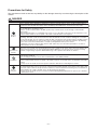
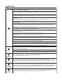
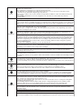
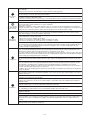
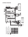
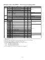
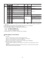
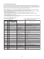
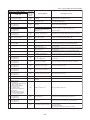
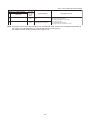
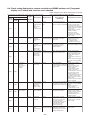
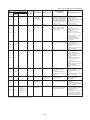
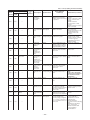
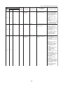
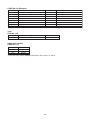
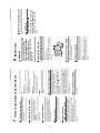
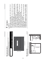
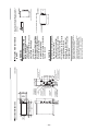
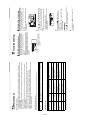
Indoor unit (including Hot Water Module)
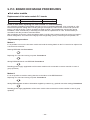
Check code
Location
Main
Outdoor 7-segment display
of
remote Check
detection
Sub-code
controller code
E25
E25
E28
E31
F01
F02
System status
—
Note:
Do not set outdoor
addresses manually.
There is duplication in
outdoor addresses set
manually.
I/F
Dropping out of All stop
outdoor unit
• Backup setting is being
Outdoor unit initially
communicating normally fails used for outdoor units.
to return signal for specified • Check power supply to
outdoor unit. (Is power
length of time.
turned on?)
• Check connection of tie
cables between outdoor
units for bad contact or
broken wire.
• Check communication
connectors on outdoor
P.C. boards.
• Check for defect in outdoor
P.C. board (I/F).
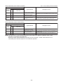
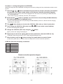
Detected
I/F
outdoor unit No.
Outdoor
follower unit
error
All stop
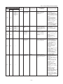
Outdoor header unit receives • Check check code
displayed on outdoor
error code from outdoor
follower unit.
follower unit.
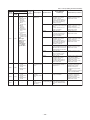
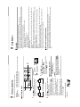
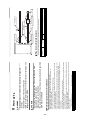
<Convenient functions>
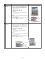
If SW04 is pressed and held
for at least 1 second while
[E28] is displayed on the 7segmentdisplay of outdoor
header unit, the fan of the
outdoor unit that has been
shut down due to an error
comes on.
If SW04 and SW05 are
pressed simultaneously, the
fans of normal outdoor units
come on.
To stop the fan or fans,
press SW05 on its own.
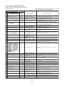
SMMS-i
(Series 4)
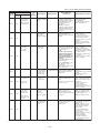
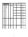
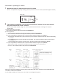
I/F
IPDU
communication
error
All stop
Communication is disrupted
between IPDUs (P.C.
boards) in inverter box.
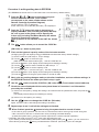
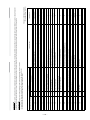
Indoor
unit
Indoor TCJ
sensor error
Stop of
Sensor resistance is infinity • Check connection of TCJ
corresponding unit or zero (open / short circuit). sensor connector and
wiring.
• Check resistance
characteristics of TCJ
sensor.
• Check for defect in indoor
P.C. board.
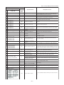
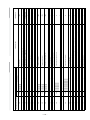
Indoor
unit
Indoor TC2
sensor error
Stop of
Sensor resistance is infinity • Check connection of TC2
corresponding unit or zero (open / short circuit). sensor connector and
wiring.
• Check resistance
characteristics of TC2
sensor.
• Check for defect in indoor
P.C. board.
E28
—
Check items (locations)
Duplicated
All stop
follower outdoor
address
E26
E31
Error detection
condition(s)
I/F
—
Address of
outdoor unit
from which
signal is not
received
normally
E26
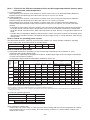
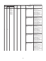
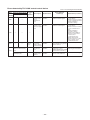
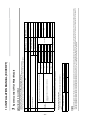
Description
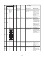
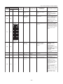
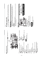
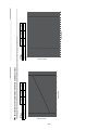
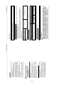
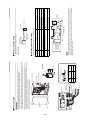
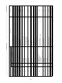
A3-IPDU Fan
1 2 3 IPDU
01 O
O
02
03 O O
04
O
05 O
O
O O
06
07 O O O
08
O
09 O
O
O
0A
O
0B O O
O
O O
0C
O O
0D O
O O O
0E
0F O O O O
Symbol O
signifies site of
IPDU error.
—
—
– 48 –
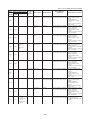
• Check wiring and
connectors involved in
communication between
IPDU-I/F P.C. board for
bad contact or broken wire.
• Check for defect in outdoor
P.C. board (I/F, A3-IPDU
or Fan IPDU).
• Check for external noise.