1
Fueland Emissions
Fueland EmissionsSystems
SpecialTools
1't-2
General
Troubleshooting
Information
I I-J
DTCTroubleshooting
lndex .... 11-7
SymptomTroubleshooting
1ndex...............
11 - 1 0
SystemDescriptions
................
11-12
Howto SetReadiness
Codes.. 11-46
PGM-FlSystem
Component
Location
Index .... 11-49
D T CT r o u b l e s h o o t i n. .g. . . . . . . . .11-52
...
MILCircuitTroubleshooting
... 11-97
DLCCircuitTroubleshooting
.. 1 1 - 1 0 9
InjectorReplacement
...............
11-111
A,/FSensorReplacement
.........1 1 - 1 1 3
HO2S
Secondary
Replacement
11-113
ECTSensorReolacement.......1 1 - 1 1 4
CMPSensorB {TDCSensor)
Replacement
11-114
I A TS e n s oR
r e p l a c e m e.n. t. . . . . 1. .1 - 1 1 5
KnockSensorReplacement
.... 1 1 - 1 1 5
CKPSensorReolacement
.......1 1 - 1 1 6
VTEC/VTC
LocationIndex .... 11-117
Comoonent
D T CT r o u b l e s h o o t i n. .g. . . . . . . . .1.1. .- 11 8
VTCOil ControlSolenoid
ValveRemoval/Test
.............
11-127
CMPSensorA Replacement
... 11-128
VTECSolenoid
Valve
R e m o v a l / l n s o e c t.i .o. n. . . . . . .11-128
...
ldle ControlSystem
Location
Index
Component
11-129
. . . . . . . . . . .1. .I.- 1 3 0
D T CT r o u b l e s h o o t i n g
A,/CSignalCircuit
T r o u b l e s h o o t i n.S. . . . . . . . . . . . . .I .t.-. t.5 5
AlternatorFRSignalCircuit
T r o u b l e s h o o t i n.S. . . . . . . . . . . . . .1. 1. .-. 1 3 4
EPSSignalCircuit
T r o u b l e s h o o t i n.S. . . . . . . . . . . . . .1.1. .-1. 3 5
Brake
PedalPosition
SwitchSignal
Troubleshooting
.............
Circuit
11 - 1 3 7
ldle SpeedInspection
11 - 1 3 8
E C Ml d l el e a r nP r o c e d u r e. . . . . . .11 - 1 3 9
FuelSupplySystem
ComponentLocationIndex
11 - 1 4 0
FuelPump
Circuit
Troubleshooting 1 1 - 1 4 1
F u e lP r e s s rue R e l i e v i n g. . . . . . . . .1. .1 - 1 4 4
F u eP
l r e s s u r e T e s. .t. . . . . . . . . . . .1. 1. .-.1. 4 5
FueL
l i n e sI n s p e c t i o.n. . . . . . . . . .1. .1. .- 1 4 6
FuelLine/Ouick-Connect
FittingsPrecautions.............
11-148
FuelLine/Ou
ick-Con
nect
F i t t i n gR
s e m o v a l. . . . . . . . . . . . .1. 1. .-.1. 4 9
FuelLine/Ou
ick-Con
nect
F i t t i n glsn s t a l l a t i o.n. . . . . . . . . .1. .1. .- 1 5 0
FuelPressure
Regulator
R e p l a c e m e .n.t. . . . . . . . . . . . . . . 1
. .1. .-.1. .5. 2
FuelFifterReplacement
...........
11-152
FuelPump/Fuel
GaugeSending
. .1. .-.1 5 3
U n i t R e D l a c e m e. .n. t. . . . . . . . . 1
F u eP
l u l s a t i oDna m o e r
R e p 1 a c e m e. n
. .t. . . . . . . . . . . . . . 1
. .1. .-.1. .5. 4
F u eT
l a n kR e o l a c e m e n
. .t. . . . . . .1. 1. - 1 5 5
F u eGl a u g e S e n dUi n igt T e s. .t . . . .1. 1 - 1 5 6
11-158
LowFuellndicatorTest
.................
IntakeAir System
C o m o o n e nLt o c a t i o nI n d e x . . . . 1 1 - 1 5 9
T h r o t t l eB o d y T e s t . . . . . . . . . . . . . . 1
. .1. .-.1 6 0
IntakeAir BypassControl
T h e r m aV
l a l v eT e s t . . . . . . . . . . .1. .1. - 1 6 1
A i r C l e a n eR
r e o l a c e m e n .t . . . . . .1. 1 - 1 6 2
A i r C l e a n eE
r lement
R e o l a c e m e n.t. . . . . . . . . . . . . . . . . 1
. .1. .-.1. .6 2
ThrottleCableAdjustment ...... 11-163
ThrottleCable
Removal/lnstallation
............
11-164
Th rottleBody Removal/
Installation
.. 11-165
Th rottleBody Disassembly/
R e a s s e m b l v. . . . . . . . . . . . . . . . . . .1. .1. .- .1. 6. 6
CatalyticConverterSystem
D T CT r o u b l e s h o o t i n. .g. . . . . . . . .1.1. .- 1 6 7
PCVSystem
D T CT r o u b l e s h o o t i n g. . . . . . . . . . .1. .1.- 1 6 8
PCVValveInsDection
a n dT e s t
. . . . . .11 -1 6 9
P C VV a l v eR e o l a c e m e n.t. . . . . . . .1.1 - 1 6 9
EVAPSystem
C o m p o n e nLt o c a t i o nI n d e x . . . . 1 1 - 1 7 0
D T C T r o u b l e s h o o t i n.g. . . . . . . . . .1. .1. - 1 7 1
EVAPTwo Way ValveTest ......11-186
FuelTank VaoorControl
ValveTest
... 11-187
E V A PC a n i s t eR
r e p l a c e m e n.t. . 1 1 - 1 8 9
FuelTank VaoorControl
V a l v eR e o l a c e m e n.t. . . . . . . . . .1. .1.- 1 8 9
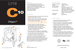
Fueland EmissionsSystems
SpecialTools
Rel. No.
(L)
@
o
@
@
@
o
@-t
@-2
O-3
@-4
@
(iD
Tool Number
ffi
W
I
o
1
1
1
/6\
l\r
)l
\-,/
\7
@
-'-,---=---1,-'.
ut/t
'jt'
o
@
(i)
I
2
/'r';-:'-;--'
At-''
UtB
o
\-
1
1
--1
a=:t=' (F
(
otv
Description
V a c u u mP u m p / G a u g e0, 3 0 i n . H g
Vacuum/Pressure
Gauge.0 4 in.Hg
BackprobeSet
Fuel PressureGaugeAdapter
PressureGaugeAdapter
FuelSenderWrench
Hose,Oil Pressure
A,/TPressureHose
A,/TLow PressureGaugeW/Panel
A,/TPressureHose,2,210 mm
A,/TPressureHoseAdapter
F u e lP r e s s u r eG a u g e
FuelPressureGauoeSet
A973X-041-XXXXX
07JAZ-0010008
07sAz-001000A
07vAJ-0040100
07NAJ-P07010A
07xAA-001010A
07zAJ-S5AA200
07406-0020201
07406-0070300
OTMAJ-PY4O11A
07MAJ-PY40120
07406-004000A
07zAJ-S5A0100
\,
)
i-==.€
*==-.2'l
-1,40-2, -3,@-4
\\h
*.'l€)
\\:
\\d
o
@
\-
11-2
a
GeneralTroubleshooting
Information
IntermittentFailures
The term "intermittentfailure" means a svstem mav
have had a failure.but it checksOK now. lf the
MalfunctionIndicatorLamp (MlL)on the dash does not
come on, checkfor Doorconnectionsor looseterminals
at all connectorsrelatedto the circuitthat Vou are
troubleshooting.
2. lf the MIL stayson, connectthe HondaPGM Tester
(A) or an OBD ll scantool to the Data Link
Connector{DLC)(B) locatedunderthe driver'sside
o f t h ed a s h b o a r d .
Opensand Shorts
"Ooen" and "Short" are common
electricalterms.An
open is a breakin a wire or at a connection.A short is
an accidentalconnectionof a wire to ground or to
anotherwire. In simple electronics,this usuallymeans
somethingwon't work at all. With complex electronics
( s u c ha s E C M s ) t h i sc a n s o m e t i m e sm e a ns o m e t h i n g
works, but not the way it's supposedto.
How to Usethe PGMTesteror a ScanTool
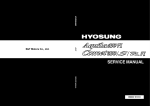
3 . T u r nt h e i g n i t i o ns w i t c hO N ( l l ) .
lf the MIL {Malfunction Indicator Lamp} has come on
'1.
S t a r tt h e e n g i n ea n d c h e c kt h e M I L { A ) .
N O T E l: f t h e i g n i t i o ns w i t c hi s t u r n e dO N ( l l ) ,a n d
the engine is not started,the MIL will stay on for
1 5 2 0 s e c o n d s( s e ep a g e1 1 - 4 6 ) .
K->;"PN/.- -:::--d V-: !
w:ix&K#
Checkthe DiagnosticTroubleCode (DTC)and note
it. Also checkthe freezedata.Referto the DTC
T r o u b l e s h o o t i nIgn d e x ,a n d b e g i nt h e a p p r o p r i a t e
troubleshootingprocedure.
5 . lf you do not find any DTCS,go to MIL circuit
t r o u b l e s h o o t i n(gs e ep a g e1 1 - 9 7 ) .
NOTE:
. Freezedata indicatesthe engineconditionswhen the
first malfunction,misfire,or fuel trim malfunction
was detected.
. The scantool and the Honda PGM Testercan readthe
DTC,freezedata,currentdata,and other Engine
Controll\4odule{EClvl)data.
. For specificoperations,referto the user's manual
that came with the scantool or HondaPGl\4Tester.
lf the MIL did not stay
lf the MIL did not come on but there is a driveability
problem,referto the Symptom TroubleshootingIndex
i n t h i ss e c t i o n .
lf you can't duplicate the DTC
Some of the troubleshootingin this sectionrequires
you to resetthe ECM and try to duplicatethe DTC.lf rhe
problem is intermittentand you can't duplicatethe code,
d o n o t c o n t i n u et h r o u g ht h e p r o c e d u r eT. o d o s o w i l l
o n l y r e s u l ti n c o n f u s i o na n d ,p o s s i b l ya, n e e d l e s s l y
r e p l a c e dE C M .
(cont'd)
11-3
Fueland EmissionsSystems
J
GeneralTroubleshootingInformation(cont'dl
How to Resetthe ECM
You can resetthe ECM in eitherof two ways:
. U s et h e O B Dl l s c a n t o o lo r H o n d aP G M T e s t e r t o
resetthe ECM memory.
Seethe OBD ll scantool or HondaPGI\4Testeruser's
manualsfor specificinstructions.
' Turn the ignition switch OFF,and removethe No. 6
ECU{ECM}(15A)fuse (A)from the under-hoodfuse/
r e l a vb o x ( B l f o r 1 0 s e c o n d s .
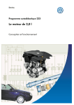
How to Removethe ECMfor Testing
1. Removethe passenger'sdashboardlower cover
{seepage 20-63),the passenger'skick panel (see
page 20-63),and the glove box (seepage 20-63).
2. Removethe ECM mounting bolts (B)and the ECM
(c),
9.8 N.m
{1.0kgf.m,7.2lbt.ft}
3 . R e m o v et h e E C M ( B ) .
How to Enda TroubleshootingSession
(requiredafterany troubleshootingl
L
4. Installthe ECM in the reverseorder of removal.
1. Resetthe ECM as describedabove.
2 . D o t h e E C Mi d l e l e a r np r o c e d u r e( s e ep a g e1 1 - 1 3 9 )
3. Turn the ignition switch OFF.
4. DisconnecttheOBD ll scantool or Honda PGM
Testerfrom the DLC.
NOTE:The ECM is part of the immobilizersystem.
lf vou replacethe ECM,it will have a different
immobilizercode. In order for the engineto start,
you must rewritethe immobilizercode with the
Honda PGM Tester.
\- ta
11-4
How to TroubleshootCircuitsat the ECM
Special Tools Required
. DigitalMultimeterKS-AHM-32-003
(1) or a
commerciallyavailabledigital multimeter
. BackprobeSet 07SAZ-0010004
(2)
1. Connectthe backprobeadapters(A) to the stacking
patchcords (B),and connectthe cords to a digital
m u l t i m e t e (r C ) .
2 . U s i n gt h e w i r e i n s u l a t i o n
a s a g u i d ef o r t h e
contouredtip ofthe backprobeadapter,gently slide
the tip into the connectorfrom the wire side until it
touchesthe end of the wire terminal.
3. lf you cannot get to the wire side of the connector
or the wire side is sealed(A),disconnectthe
connectorand probe the terminals(B)from the
terminal side. Do not force the Drobeinto the
connector.
Do not puncturethe insulationon a wire.
Puncturescan causeDooror intermittent
electricalconnections.
07sAz-001000A
(cont'd)
11-5
Fueland EmissionsSystems
Information(cont'd)
GeneralTroubleshooting
ECMUpdatingand Substitutionfor Testing
Special Tools Bequired
HondaInterfaceModule (HlM) EOS05435570
(
How to Substitute the ECM
'1.
Removethe ECMf rom the vehicle.
2. Installa known-goodECM in the vehicle.
Usethis procedurewhen you haveto substitute a
known-goodECM in a troubleshootingprocedure.
does not alreadyhave
U pdatethe ECMonly if the ECN4
the latestsoftwareloaded,
NOTE;
. lMakesure the batteryis fully chargedbeforeyou
updatethe ECN4.
. To preventECMdamageduring the update,do not
turn the ignition switch OFF,and do not use any of
the vehicle'selectricaldevices(light,horn, radio,etc. ).
3 . R e w r i t et h e i m m o b i l i z ecr o d ew i t h t h e E C M
replacementprocedurefrom the Honda PGM
Tester.lt allows you to startthe engine.
4. After completingyour tests,reinstallthe original
E C Ma n d r e w r i t et h e i m m o b i l i z ecr o d ew i t h t h e
E C Mr e p l a c e m e nptr o c e d u r e
o n t h e H o n d aP G M
T e s t e ra g a i n .
How to Update the ECM
1. Turn the ignition switch ON (ll).Do not startthe
e n gI n e .
2. Connectthe HondalnterfaceModule (HlM)to the
Data Link Connector{DLC)(A) locatedunderthe
d r i v e r ' ss i d eo f d a s h b o a r d .
L
EOS05A35570
Do the ECM updateprocedureas describedon the
HlN4label and in the ECM updatesystem.
\-
11-6
I
DTCTroubleshootingIndex
DTC
Temporary
DTC
Detection ltem
{MlLindication*)
P 0 0 1 (05 6 )
VariableValveTiming Control{VTC)Oil Control
P 0 0 1 (15 6 )
P0011
P 0 1 0 (73 )
P 0 1 0 (83 )
P 0 1 1 2( 1 0 )
(10)
P01r3
P 0 1 1 6{ 8 6 )
P0116
S o l e n o i dV a l v eM a l f u n c t i o n
VariableValveTiming Control(WC) System
Malfunction
Note
{ s e ep a g e11 ' 11 8 )
( s e ep a g e1 1 -11 9 )
(MAP)SensorCircuit
ManifoldAbsolutePressure
LowVoltaqe
(MAP)SensorCircuit
ManifoldAbsolutePressure
HiqhVoltaqe
( s e ep a g e1 ' l - 5 2 1
IntakeAir Temperature(lAT)SensorCircuitLow
Voltaoe
IntakeAir Temperature(lAT)SensorCircuitHigh
Voltaoe
EnglneCoolantTemperature(ECT)Sensor Range/
PerformanceProblem
(seepage 11-55)
( s e ep a g e1 1 - 5 3 )
(seepage '11-56)
{ s e ep a g e1 1 - 5 7 )
P0117
{6)
(ECT)SensorCircuit
EngineCoolantTemperature
LowVoltaqe
( s e ep a g e1 1 - 5 8 )
P 0 1 1{86 )
EngineCoolantTemperature(ECT)SensorCircuit
Hiqh Voltaqe
Throttle Position(TP)SensorCircuitLow Voltaqe
Throttle Posltion(TP)SensorCircuitHiqh Voltaoe
CoolinqSVStemMalfunction
Air Fuel Ratio(Ay'F)
Sensor(Sensor1) No Activity
Detected
SecondaryHeatedOxygen Sensor (SecondaryHO2S)
(Sensor2) CircuitLow Voltaqe
SecondaryHeatedOxygen Sensor (SecondaryHO2S)
( S e n s o2
r ) C i r c u i tH i q hV o l t a q e
SecondaryHeatedOxygen Sensor (SecondaryH02S)
( S e n s o2
r )SlowResDonse
SecondaryHeatedOxygen Sensor(SecondaryH02S)
(Sensor2) HeaterCircuitMalfunction
{ s e ep a g e1 1 - 5 9 )
P 0 1 2 t27 \
P 0 1 2 {37 )
P 0 1 2 8( 8 7 )
P 0 1 3 4( 4 1 )
P0128
P 0 1 3 (76 3 )
P0137
P 0 1 3 8( 6 3 )
P0138
P 0 1 3 (96 3 )
P0139
P 0 1 4 1( 6 5 )
P 0 1 7 1( 4 5 )
PO112l'45)
PO\11
PO\l2
P0300andany
of
P 0 3 0 (17 1 )
(721
PO302
P0303(73)
P0304(74)
P0301(7'1)
P0300andany
of
P0301
P0302
P0303
P0304
P0301
No. 1 Cyl n d e rM i s f i r e
P0302
No.2 Cvl n d e rM i s f i r e
P0303
N o . 3 C v l nder Misfire
FuelSvstemToo Lean
FuelSystemToo Rich
R a n d o mM i s f i r e
( s e eD a q e1 1 - 6 0 )
( s e ep a q e1 1 - 6 2 )
( s e eD a q e1 1 - 6 4 )
( s e ep a g e1 1 - 6 5 )
( s e ep a g e1 1 - 6 5 )
( s e ep a g e1 1 - 6 6 )
( s e ep a g e1 1 - 6 7 )
( s e ep a g e1 1 - 6 8 )
( s e ep a q e1 1 - 7 0 )
( s e eo a o e1 1 - 7 0 )
( s e ep a g e1 1 - 7 1 )
{ s e ep a g e1 1 - 7 2 )
{ s e ep a q e11 - 7 2 )
( s e eo a q e1 1 - 7 2 )
P0303(73)
P0304{74)
P0304
N o . 4 C v l nder Misfire
{seeDaqe11-72)
" ; T h e s e D T C sa r e i n d i c a t e db y a b l i n k i n gm a l f u n c t i o ni n d i c a t o lra m p ( M l L ) w h e nt h e S C Ss e r v i c es i g n a l i n e i s
jumped with the Honda PGM Tester.
P0302(721
{cont'd)
11-7
Fueland EmissionsSystems
DTCTroubleshootingIndex(cont'd)
(
\
KnockSensorCircuitN4alfunction
PO4i{
P 0 4 5 1( 9 1 )
TU45I
P0452
CrankshaftPosition(CKP)SensorIntermittent
( s e ep a g e1 1 - 7 8 )
CamshaftPosition(CMP)SensorA No
CamshaftPosition(CMP)SensorA Intermiftent
( s e eo a q e1 1 - 1 2 1
i s e ep a g e1 1 - 1 2 1 )
Phqse
G
Yetrgb-le
VelyeTiTing_controlll/T!)
s e eo a o e1 1 - 1 2 2
CqJalystSystemElficie-ncy
Below Threshold
s e eo a q e11 -1 6 7
( F T PS
) e n s o rR a n g e / P e r f o r m a n c e( s e e p a g e l l 1 7 1 )
F u e lT a n kP r e s s u r e
SensorCircuitLow V
FuelTank Pressure(FTP)SensorCircuitHigh V
V e h i c l eS D e e dS e n s o r
C i r c u i tM a l fu n c t i o n
E n g i n eC o n t r o M
l o d u l e( E C N 4P)o w e rS o u r c eC i r c u i l
11-172
s e eD a q e1 1 - 1 3 0 )
( s e ep a g e11 - 8 1 )
SeriaC
l o m m u n i c a t i o Ln i n kM a l f u n c t i o n
Referto the l\4ultiplex
ControlSystem
T r o u b l e s h o o t i n{gs e e
P 1 1 0(61 3 )
(BARO)
Barometric
Pressure
SensorRange/
PerformanP
c er o b l e m
( s e ep a g e11 - 8 3 )
P 1 1 0(?1 3
( B A R OS
) e n s o rC i r c u i tL o w
BarometriP
c ressure
( s e ep a S e11 ' 8 3 )
P 11 0 8( t s '
( B A R OS
) e n s o rC i r c u i tH i g h
BarometriP
c ressure
{ s e ep a g e1 1 - 8 3 )
P112111)
P't121
T h r o t t l eP o s i t i o n{ T P iS e n s o rS i g n a lL o w e rT h a n
( s e ep a g e1 1 - 6 3 )
P1122ll J
Pl122
T h r o t t l eP o s i t i o n( T P )S e n s o rS i g n a lH i g h e rT h a n
tsee page I r-oJ,
i j 1 1 2 8( 5 )
P11f,.8
Pr 158 (48)
(l\,4AP
M a n i { o l dA b s o l u t eP r e s s u r e
S }e n s o rS i g n a l
G;tp"s" 1154)
Loqer Than Expected
( * " p a S e11 5 4 )
ManifoldAbsolutePreisure (MAP)SeiiioiSgnul
H i q h e rT h a nE x
( s e ep a g e1 1 - 8 4 )
A i r F u e lR a t i o( A V FS) e n s o r( S e n s o r1 ) R a n g e /
R e r f o r m a n cP
eroblem
A i r F u e lR a t i o { A " FS) e n s o r{ S e n s o 1
r ) A F S T e r m i n a l ( s e ep a g e11 - 8 5 )
P 11 5 9( 4 8 )
'l)
A i r F u e lR a t i o1 A V FS)e n s o ri s e n s o r A F S+ T e r m i n a l ( s e ep a g e11 - 8 6 )
P 1 1 6 3( 6 1
P 1 1 6 4( 6 1 )
Air FuelRatio{A,/F)Sensor{SensorI ) Slow Response
( s e ep a g e 11 - 8 8 )
A i r F u e lR a t i o( A / F )S e n s o r( S e n s o r1 ) R a n g e /
P 11 2 9( 5 )
P 1 1 5 7( 4 8 )
l\."
-
P 11 6 6( 4 1 )
( s e ep a g e1 1 - 8 9 )
Air Fuel Ratio(4,/F)Sensor(Sensor1) HeaterCircuit
Malfunction
Air Fuel Ratio(A,/F)Sensor(Sensor1) HeaterSystem ( s e ep a g e1 1 - 9 1 )
P 11 6 7( 4 1 )'
Malfunction
" : T h e s eD T C Sa r e i n d i c a t e db y a b l i n k i n gM I L w h e n t h e S C Ss e r v l c es i g n a l i n e i s j u m p e dw i t h t h e H o n d aP G M
Tester.
* 1 r' 0 2 m o d e l
\.
11-8
a
DTC
Temporary
DTC
Detectionltem
{MlLindication*l
P1259t22J
VTECSystem l\4alfunction
P1291t20\
ElectricalLoad Detector(ELD)CircuitLow Voltaqe
P1298(20)
ElectricalLoad Detector(ELD)CircuitHiqh Voltaqe
P 1 3 6 1( 8 )
P 1 3 6 (28 )
P'r456(90)
P1456
(90)
P14s7
P1457
P 1 5 0 (51 0 9 )
P1505
(14)
P1519
P 1 6 0 7( )
CamshaftPosition(CMP)SensorB (Top DeadCenter
(TDC)Sensor)IntermittentSional InterruDtion
CamshaftPosition(CMP)Sensor B (Top DeadCenter
( T D C )S e n s o r N
) o Siqnal
EvaporativeEmissions(EVAP)ControlSystem
Leakaqe(FuelTank Svstem)
EvaporativeEmissions(EVAP)ControlSystem
Leakaqe(EVAPCanisterSvstem)
PositiveCrankcaseVentilation(PCV)Air Leakaqe
ldle Air Control(lAC)ValveCircuitMalfunction
EnginC
e o n t r oM
l o d u l e( E C MI)n t e r n aCl i r c u i t
Malfunction
Page
( s e eD a q e1 1 - 1 2 3 )
( s e eD a q el 1 - 9 2 )
( s e eo a o e1 1 - 9 3 )
( s e ep a g e1 1 - 9 5 )
( s e ep a g e1 1 - 9 5 )
( s e ep a g e1 1 - 1 7 5 )
( s e ep a g e1 ' l - 1 8 0 )
( s e eo a q e1 1 - 1 6 8 1
{ s e ep a q e1 1 - 1 3 1 )
( s e ep a g e11 - 9 6 )
" : TheseDTCSare indicatedby a blinking MIL when the SCSservicesignal line is jumped with the Honda PGM
Tester.
11-9
Fueland EmissionsSystems
Symptom TroubleshootingIndex
\
When the vehiclehas one of these symptoms,checkthe diagnostictrouble code (DTC)with the scantool. lf there is no
DTC,do the diagnosticprocedurefor the symptom, in the sequencelisted,until you find the cause.
Svmotom
E n g i n ew i l l n o t s t ar t
(MlL works OK, no DTCSset)
Diaqnostic procedure
1. Testthe battery{seepage 22-50).
2. Testthe starter(seepage 4-8).
3. Troubleshootthe fuel pump circult(seepage 11
141).
E n g i n ew i l l n o t s t a r t( M l L
comes on and stayson, or
n e v e rc o m e so n a t a l l ,n o
DTCSset)
Enginewill not start
(immobilizerindicatorstays
on or flashs)
Troubleshootthe l\4lLcircuit(seepage 1
Hardstarting
(MlLworksOK,no DTCS
set)
1. Testthe battery(seepage22-50).
2 . C h e c k t h ef u e l p r e s s u r e( s e ep a g e1 1 - 1 4 5 ) .
Coldfast idle too low
(MlL works OK. no DTCSset)
Coldfast idle too high
(MlL works OK, no DTCSset)
1 . D o t h e E C Mi d l e l e a r np r o c e d u r e( s e ep a g e1 1 - 1 3 9 ) .
2 . C h e c k t h ei d l e s D e e d( s e ep a q e1 1 - 1 3 8 ) .
' ] D o t h e E C I \ 4i d l e l e a r np r o c e d u r e( s e ep a g e11 -1 3 9 ) .
2. C h e c k t h ei d l es p e e d{ s e ep a g e1 1 - 1 3 8 ) .
'1-'163).
the throttlecable (seepage 1
3 . Inspect/adjust
Inspectand test the throttle body {seepage 11-160}.
( s e ep a g e1 1 - ' 1 3 9 ) .I n t a k ea i r l e a k s
1 . D o t h e E C Mi d l e l e a r np r o c e d u r e
2 . C h e c kt h e i d l es p e e d( s e ep a g e1 1 - 1 3 8 ) .
3, Inspecvadjustth e throttlecable (seepage 11''163).
4. Insoectand test the throttle bodv (seepaqe 11-160)
1 . D o t h e E C I Vi d
I l e l e a r np r o c e d u r e( s e ep a g e11 -1 3 9 ) . Vacuum hose clogged/
cracked/poor
2. TroubleshootthealternatorFRsignalcircuit (see
p a g e1 1 - ' 1 3 4 ) .
connectron
3. InsDectand test the throttle bodv {seepaqe 11-160).
1 . D o t h e E C Mi d l e l e a r np r o c e d u r e
{ s e ep a g e1 ' j - 1 3 9 ) .
t e a l t e r n a t oFr Rs i g n a lc i r c u i t ( s e e
2 . T r o u b l e s h o ot h
p a g e1 1 - 1 3 4 ) .
ldle speedfluctuates
(MlL works OK, no DTCSset)
After warming up, idle speed
is below specificationswith
no load
{MlL works OK, no DTCSset)
After warming up, idle speed
is above specificationswith
no toao
(MlL works OK. no DTCSset)
Low power
(MlL works OK, no DTCSset)
E n g i n es t a l l s
(MlL works OK. no DTCSset)
'1-97).
Also check lor
Low compressron
N o i g n i t i o ns p a r k
l n t a k ea i r l e a k s
L o c k e du p e n g i n e
B r o k e nt i m i n gc h a i n
Contaminatedfuel
Troubleshootthe immobilizersystem (seepage 22-165).
1 . C h e c kt h e f u e l p r e s s u r e ( s e e p a g e l l - 1 4 5 ) .
2. Inspectand test the th roftle body (seepage 11-160).
3 . I n s p e c v a d j u tsht e t h r o t t l ec a b l e( s e ep a g e1 1 - ' 1 6 3 ) .
1.
2.
3.
4.
D o t h e E C Mi d l el e a r np r o c e d u r e( s e ep a g e1 ' l ' 1 3 9 ) .
C h e c kt h e f u e l p r e s s u r e { s e e p a g e l l - 1 4 5 ) .
C h e c kt h e i d l es p e e d( s e ep a g eI 1 - 1 3 8 ) .
Troubleshootthebrakepedal positionswitch signal
c i r c u i t( s e ep a q e1 1 - 1 3 7 ) .
Low compression
I n t a k ea i r l e a k s
Contaminatedfuel
\-
Low compressron
C a m s h a ftti m i n g
problem
E n g i n eo i l l e v e l
prootem
l n t a k ea i r l e a k s
F a u l t yh a r n e s sa n d
sensorconnections
\-
11-10
Symptom
Difficultto refuel
(MlL works OK. no DTCSset)
Fueloverflowsduring
refueling
(No DTCSset)
Diagnosticprocedure
1 . T e s t t h e f u e lt a n kv a p o rc o n t r o lv a l v e { s e e p a g e1 ' l 2. 1471.
I n s p e ctth e f u e lt a n kv a p o rc o n t r o ls i g n a lt u b e
3. betweenthe fuel pipe and the fuel tank vapor
control valve.
4. Inspectthe fuel tank vapor vent tube betweenthe
EVAPcanisterand the fuel tank vapor control valve.
Checkthe EVAPcanister.
Replacethe fuel tank vapor control valve (seepage '11
189).
Also checktor
M a l f u n c t i o n i ngga s
s t a t i o nf i l l i n gn o z z l e .
Malfunctioninggas
stationfilling nozzle.
11-11
Fueland EmissionsSystems
SystemDescriptions
\
{
ElectronicControl System
The functionsof the fuel and emlssioncontrol systemsare managedby the enginecontrol module (ECM).
Fail-safeFunction
When an abnormalityoccursin the signalfrom a sensor,the ECI\4ignoresthat signaland assumesa pre-programmed
value for that sensorthat allowsthe enqineto continueto run.
Back-up Function
When an abnormalityoccursin the ECM,the injectorsare controlledby a back-upcircuitindependentof the systemto
p e r m i tm i n i m a ld r i v i n g .
Self-diagnosis
When an abnormalityoccursin the signalfrom a sensor,the ECM suppliesground for the malfunctionindicatorlamp
{MlL) and storesthe diagnostictrouble code {DTC)in erasablememory.When the ignition is first turned on, the EClvl
suppliesground to the l\4lLfor 15 to 20 secondsto checkthe M lL bulb condition.
Two Driving Cycle Detection Method
"two driving cycle detectionmethod" is usedfor some self-diagnostic
functions.
To preventfalse indications,the
When an abnormalityoccurs,the ECM storesit in its memory. When the same abnormalityrecursafterthe ignition
s w i t c hi s t u r n e dO F Fa n d O N ( l l )a g a i n ,t h e E C Mt u r n so n t h e M l L .
\
\.
11-12
ECMData
You can retrievedata from the ECI\4by connectingthe OBD ll scantool or the Honda PGM Testerto the data link
connector(DLC).The items listedin the table below conform to SAE recommendedpractice.The HondaPGM Tester
also readsdata beyondthat recommendedby SAEto help you find the causesof intermittentproblems.
The "operatingvalues" listedare approximateand may vary dependingon the environmentand the individual
vehicle.
Unlessnoted otherwise,"at idle speed" means idling with the enginecompletelywarmed up in the neutralposition,
and the A,/Cand all
Diagnostic
Trouble Code
(DTC}
lf the ECM delectsa problem, it will store it as a code
consistingof one letterand four numbers.Dependingon
the problem,an SAE-definedcode (Poxxx)or a Honda,
definedcode {P1xxx)will be output to the tester.
l f n o p r o b l e mi s
detected,there is no
ourpul.
YES
TheECI\4
computesenginespeedfromthe signalssent
N e a r l yt h e s a m ea s
position(CKP)sensor.Thisdatais
fromthe crankshaft
tachometerindication
usedfor determining
thetimeandamountof injectedfuel. At idle speed;
Manifold
Absolute
Pressure
(MAP)
The ECMconvertspulsesignalsfrom the vehiclespeed
sensor(VSS).
N e a r l yt h e s a m ea s
speedometer
indication
The absolutepressurecausedin the intakemanifold by
e n g i n el o a da n d s p e e d .
Withenginestopped:
YES
Nearlythe same as
almospnencpressure.
At idle speed:about
20 4'1kPa
( 1 5 0 3 1 0m m H g ,
6 - 1 2 i n . H q ) . 0 . 71 . 3V
The ECTsensorconvertscoolanttemperatureinto voltage W i t h c o l d e n g i n e :
and signalsthe ECM.The sensor is a thermistorwhose
S a m ea s a m b i e n t
internalresistancechangeswith coolanttempetature.The temperatureand IAT
ECM usesthe voltagesignalsfrom the ECTsensorto
With enginewarmed
determinethe amount of injectedfuel.
u p ; a b o u t1 1 6 2 ' 1 2 " F
1 0 0 ' c ) . 0 . 5 - 0 .v8
Air Fuel Ratio
( A y ' FS)e n s o r .
(Sensor1)
Secondary
Heated
Oxygen
Sensor
(Secondary
H02S,
Sensor2)
The A,/Fsensordetectsthe oxygen content in the exhaust 0.0- 1.25 V
g a s a n d s e n d sv o l t a g es i g n a l st o t h e E c l v l ,B a s e d o n t h e s e 8 . 0 1 1 . 0 m A ( P G M
signals,the ECMcontrolsthe airlfuel ratio.When the
I Tester)
oxygen contentis high (that is, when the ratio is leaner
At idle speed:
than the stoichiometricratio),the voltagesignal is Iower. about 0.1 0.9 V
When the oxygencontent is low (that is, when the ralio is
richerthan the stoichiometricratio).the voltagesignal is
higher.The A'lFsensorsignalsare electricalcurrentthat
are indicatedas voltaqe on the
The HO2Sdetectsthe oxygen contentin the exhaustgas
0 . 0 1 . 2 5V
a n d s e n d sv o l t a g es i g n a l st o t h e E C M .B a s e do n t h e s e
At idle speed:
signals,the ECMcontrolsthe airlfuel ratio.When the
a b o u t0 . 1 0 . 9V
oxygen contentis high (that is, when the ratio is leaner
than the stoichiometricratio),the voltagesignal is lower.
When the oxygen content is low (that is, when the ratio is
r i c h e rt h a nt h e s t o i c h i o m e t r irca t i o ) t, h e v o l t a g es i g n a li s
NO
(cont'd)
11-13
Fueland EmissionsSystems
r a
SystemDescriptions(cont'd)
ECMData(cont'd)
Description
"open" or "closed".
Fuelsystem statusis indicatedas
Closed:Basedon the A,/FSensoroutput,the ECM
determinesthe airlfuel ratio and controlsthe amount of
injectedfuel.
Open: lgnoringAy'FSensoroutput,the ECM refersto
signalsfrom the throttle position{TP),manifoldabsolute
pressure(MAP),intakeair temperature(lAT),barometric
pressure(BARO),and enginecoolanttemperature(ECT))
sensorsto controlthe amount of iniectedfuel.
The airlfuel ratio correctioncoefficientfor correctingthe
Short Term
amount of injectedfuel when the fuel system status
FuelTrim
is "closed." When the ratio is leanerthan the
sloichiometricratio,the ECM increasesshort term fuel
trim gradually,and the amount of iniectedfuel increases.
The airlfuel ratio graduallygets richer,causinga lower
oxygen content in the exhaustgas. Consequently,the
short term fuel trim is lowered,and the ECM reducesthe
amount of injectedfuel.
This cvcle keepsthe airlfuelratio closeto the
stoichiometricratio when in closedloop status.
Long term fuel trim is computedfrom short term fuel trim
LongTerm
and indicateschangesoccurringin the fuel supply system
F u eT
l rim
over a long period.
l f l o n gt e r m f u e lt r l m i s h i g h e rt h a n 1 . 0 0t,h e a m o u n lo f
injectedfuel must be increased.lf it is lower than 1.00,the
amount of injectedfuel must be reduced.
The IAT sensorconvertsintakeair temperatureinto
IntakeAir
Temperature v o l t a g ea n d s i g n a l st h e E C M .W h e n i n t a k ea i r
temperatureis low, the internalresistanceofthe sensor
{IAT)
increases,and the voltagesignal is higher.
Basedon the acceleratorpedal position,the opening
Throttle
anole of the throttlevalve is indicated.
Position
lgnitiontiming is the ignition advanceangle set by the
lgnition
ECM.The ECM matchesignitiontiming to driving
Timing
conditions.
Data
FuelSystem
Status
Calculated
L o a dV a l u e
(cLV)
cLV is the enoine load calculatedfrom IMAPdata.
Opera'tingValue
At idle speed:closed
FreezeData
YES
o.7 1.5
YES
0.8 1.2
YES
w
W i t h c o l de n g i n e :
S a m ea s a m b i e n t
a n dE C T
temperature
YES
At idle speed:
a b o u t1 0%
At idle speed:8" t 5"
| ' t u L w n e nr n e > L )
s e r v i c es i g n a l i n e i s
jumped with the Honda
PGM Tester
At idle speed:
12 34%
At 2.500rpm with no
toao:
't4- 34%
YES
NO
YES
\.,
11-14
J/-\
-1\_/
BEIAY2
A/C CLUTCHRELAY
I
)
RAOIATOR
T
UNDER.HOOD
FUSE/RELAY
BOX:
(8oA)
ONo. 19BATTERY
ONo.6 ECU(ECM)(15A1
(3)No.20lG
{40A1
{Canada:50A}
ONo.l4 OPTION
{40A1
€)No.9 BACKuP (7.5A1
lo)No.7 HORN,STOP{15A}
UNDER.DASH
FUSE/RELAY
BOX:
ONo. 17FUELPUMP
{15A}
@No.,t ACG{10A)
ONo.1 IGNCOIL(1sA)
q)No.10METER
(7.5A)
0)No.14A/C CLUTCH
RELAY
IlOA)
@No.2+B LAF(A/F)
(2OA)
HEATER
(cont'd)
11-15
Fueland EmissionsSystems
SystemDescriptions(cont'dl
a
\
ECMElectricalConnections
MAPSENSON
No. INJECTOR
No,2INJECTOR
TPSENSOR
No.3 INJEC]OB
No./tINJECTOF
IATSENSOR
ECTSENSOB
\'
CMP SENSORB
(TDCSENSOSJ
CKPSENSOR
F€VERSELOCK
SOLENOIDVAIVE
\-
11-16
A/FSENSOR
EVAPCANISTE6
PURGEVAIVE
EVAPCANISTER
VENTSHUTVATVE
A/FSENSOR
(sENSOn 1)
sotENotovAtvE
CMP SENSOFA
VIC OIL CONTROL
SO!ENOIDVALVE
No. 1 IGNITIONCOIL
wEcorl
N o . 2 l G N l l l O NC O I L
No. 3 IGNITIONCOIL
PRESSUSESWTICH
VTEC SOLENOID
No. a IGNITIONCOIL
{cont'd)
11-17
Fueland EmissionsSystems
SystemDescriptions(cont'd)
\
ECMElectricalConnections
ARAKEPEDAL
POStTtONSWTTCH
GAUGEASSEMBLY
IMMOBILPENUN|T
\
EPSCONTROTUNIT
TERMINALLOCATIONS
\-
11-18
ECMInputsand Outputsat ConnectorA (31P)
2
1
AFS]TC ]GP2
'10
SG2
t1
3
IGPl
^:^ I -:,
12
ACV
22
23
HTC+ LG2
6
AFS+
15 T6
TPS AFS_
26
25 CMPB
CMPA(rDc)
I
KS
1
CKP
18
1 9 2A
V S S IVAP vcc2
21
vccl
27
28
29
30
tGPts,lrcPts3tGPts2GPLS
1
Wire side ol femaleterminals
NOTE:Standardbatteryvoltageis 12V.
Terminal Who color
numb€r
ELKAVHT
forminal name
2
YEUBLK
AFSHTC(AIRFUELRATIO
(4./F)SENSOR
HEATER
CONTROL}
IGP2(POWEB
SOURCE)
3
YEUBLK
IGPl {POWER
SOURCE)
4
5
6
1
9
10
12
18
PG2(POWER
GROUND
PG1(POWER
GROUND
AFS+ (AIRFUELRATIO
(A,/F}SENSOR,
SENSOR1
+ stDE)
8LU
CKP(CRANKSHAFT
POSITION
SENSOR)
BED/BLU
) KS E N S O B )
YEL
2 {SENSOR; R O U N D )
G 1{ S E N S O R
;ROUND)
BLIVRED IACV(IDLEAIRCONTROL
(IAC)VALVE)
RED/BLK TPS(THROTTLE
POSITION
SENSOR)
REDI/EL AFS (AIRFUELRATIO
(4,/F)SENSOR,
SENSOB1
SIDE)
WHT/GRN V S S ( V E H I C L ES P E E D
BLK
BLK
RED
SENSOR)
Description
Signal
DrivesAy'Fsensorheater
Withignit'onswitchON {ll):batteryvoltage
Withfullywarmedup enginerunnang:
0V
Powersourcefor the ECM
circuit
Powersourcefor the ECM
Withthe ignitionswitchON 1ll):batteryvoltage
Withthe ionitionswitchOFF:about0 V
Withthe ignitionswatch
ON {ll):batteryvoltage
Withthe ionitionswitchOFF:about0 V
Lessthan 1.0V at all times
Lessthan 1.0V at all times
Groundforthe ECMcircuit
Groundforthe ECMcircuit
DetectsAy'Fsensor
{sensor1)signal
Detects
CKPsensorsignal
Withenginerunning:pulses
Detectsknocksensorsiqnal
Sensorqrounr
Sensorqroun(
DrivesIACvalve
pulses
Withenqineknocking:
Lessthan1.0Vat elltimes
L e s s t h a 1n . 0 Va t a l l t i m e s
Withenginerunningrdutycontrolled
Detects
TPsensorsignal
Withthrottlefullyopen:about4.8V
Withthronlefullvclosed:ahout0-5V
Detects!y'Fsensor
( s e n s o1r) s i g n a l
Detects
VSSsignal
WathignitionswitchON (lli andfrontwheels
rotating:
cyclesfrom about0 V to about5 V or
(cont'd)
11-19
Fueland EmissionsSystems
\. il
SystemDescriptions{cont'd)
ECMInputsand Outputsat ConnectorA (31P)
1
AFS]TC
2
GP2
3
IGPl
4
PG2
12
10
11
SG2 sG1 IACV
22
23
AFS LG2
HTC+
5
6
PG.1 AFS+
'15 1 6
TPS AFS_
26
25 CMPB
Ct\.4PA
(rDc)
I
KS
1
CKP
18
1 9 20
V S S IVAP vcc2
21
vccl
29
30
27
28
IGPLS,I
IGPLS4
IGPLS3
IGPLS2
Wire side of femaleterminals
NOTE:Standard
batteryvoltageis 12V.
[€rminal namo
Description
Jorminal Wirecolor
number
19
DetectsMAPsensorsignal
GRN/RED MAP(MANIFOLD
PRESSURE
ABSOLUTE
SENSOR)
YEUBLU VCC2(SENSOR
VOLTAGE) P r o v i d e ss e n s o r v o l t a g e
20
21
YEURED VCC](SENSOB
VOLTAGE) Provides
sensorvoltage
22
AFSHTC- (AIRFUEL
Detectsa,/Fsensorheater
RATIO(A"iFiSENSOR
voltage
+ SIDE)
HEATER
CONTROL
BRN?ryE
L
LG2(LOGIC
GROUND
roundfor the ECMcircu
1(L
roundfor the ECMcircu
BRN?ryE
L
D e t e c t sC M P s e n s o r A
BLU,^/VHT CMPA (CAMSHAFT
A)
stonal
POSITION
SENSOR
Detects
GRN
CMPB CAMSHAFT
CMPsensor8 (TDc
(CMP)SENSOB sensor)
POSITION
B (TDC(TOPDEADCENTER
SENSORi)
I G P L S 4{ N o .4 I G N I T I O N
DrivesNo, 4 ignitioncoi
BRN
23
24
25
26
27
COILPULSE)
I G P L S 3{ N o . 3 I G N I T I O N
COILPULSE)
28
WHT/BLU
29
GNITION
BLU/RED l G P L S 2 l N o .I 2
COILPTJLSE)
YEUGRN IGPLSI(No.1 IGNITION
co PlltsF)
30
Signal
With ignitionswitchON (ll):about3 V
A t i d l e : a b o u t 1 . 0V ( d e p e n d i n go n e n g i n e s p e e d )
With ignitionswitchON {ll):about5 V
WithionitionswitchOFF:about0V
WithignitionswitchON {ll):about5 V
With ionitionswitchOFF:about0V
W i t h i g n ; t i o ns w i t c h O N l l l ) : b a n e r y v o l t a g e
\.
Lessthan1.0V at alltimes
L e s st h a n
'1.0
V at alltimes
Withenginerunning:pulses
Withenginerunning:pulses
WithignitionswitchON (ll)rabout0 v
Withenginerunning:pulses
O r i v e s N o . 3 r g n i t i o nc o i
DrivesNo.2 ignitioncoil
DrivesNo. I ignitioncoil
\.
11-20
a
a
Wire side o{ femaleterminals
NOTE:Standardbafteryvoltageis 12V.
Terminal
numo€t
Wirecolor
[erminal name
Description
BLUAvHT VTC+ lVTCOILCONTBOL DrivesVTCoilcontrol
2
3
4
5
6
7
8
9
10
'17
18
21
23
VALVE+SIDE)
SOLENOID
lNJa{No.4INJECTOR)
Jo.3INJECTORI
BL
)TOR)
R1
lNJl 1No.I INJECTOR)
BRN
FAN
FANC(RAOIATOR
GRN
CONTROL)
LOCK
GRN/vVHT RVS(REVERSE
VALVE)
SOLENOID
Drives o. 4 iniector
Drives o.3 iniector
Drives o . 2 i n i e c t o r
DrivesNo. 1 iniector
Drivesradiatorfan relay
Signal
WithignitionswitchON (ll):0 V
At idle:dutycontrolled
With radiatorfan running:about0 V
With radiatorfan stopped:battervvoltaoe
Drivesreverselocksolenoid Withvehiclespeedbelow9.4mph (15km/h):
batteryvoltage
Withvehiclespeedabove12.5mph (20km/h):0 V
Withthe ignitionswitchON (ll):about0.1 4.8V
DetectsECTsensorsignal
COOLANT
REDAVHT ECT(ENGINE
ideoendino
on enoinecoolanttemDerature)
TFMPFRATURE
SENSOR)
VTEcoil pressure Withengineat low enginespeed:about0 .
Detects
BLU/BLK VTPSW(VTECOIL
Wirhenoineat hiohenoinesoeed:battervvoltaqe
PRFSSTIRF
SWITCH)
switch sional
L signal With ignitionswit'chON (ll):about0 V
L
Detects
alternator
WHT/BLU ALTL(ALTEBNATOR
Whh enoinerunnino:battervvoltaqe
SIGNAII
FBsignal Withenginerunning:about0 V- 5 V
FR
Deteclsalternator
WHT/RED ALTF(ALTERNATOR
load)
on electrical
S I GN A L I
{deoendinq
DrivesVIECsolenoidvalve A t i d l e : a b o u t 0 V
GRN/YEL VTS {VTECSOLENOID
With ignitionswitchON {ll):about0.1V 4.8v
l.lcnen.iino
on intakeairtemoerature)
Withenginerunning:about0 V 5 V
control
Sendsalternator
(.lcocn.lino
on electrical
ioad)
purge Withenginerunning,enginecoolantbelow149'F
DrivesEVAPcanister
batteryvoltage
valve
165'C):
Withenginerunning,enginecoolantabove149'F
165"C):
dutvcontrolled
W i t h t h e i g n i t i o n s w i t c h O N ( l l ) :0 V
BLK/Vr'HT VTC (VTCOILCONTROL DrivesVTCoilcontrol
SOIFNOIDVALVE SIDE)
IAT(INTAKE
AIR
TEMPERATURE
SENSOR)
WHT/GRN ALTC(ALTERNATOR
CONTROL)
YEUBLU PCS{EVAPORATIVE
EMISSION
CANISTER
PURGE
VALVE)
REDI/EL
DetectsIATsensorsignal
(confd)
11-21
Fueland EmissionsSystems
L
SystemDescriptions(cont'dl
ECMlnputsand Outputsat ConnectorE (31P}
1
iMo
FPR
2
3
sr-{]zsLG3
22
23
24
BKSWK-LINESEFMJ
6
1
$1025 MRLY
HTC
16
14
15
18
FTP ELD EPS
ACC
LD
21
26
rMo
NEP
CD
8
AFS
HTCR
4
SG3
I
20
21
Z/VBS VSV
29
scs
30
31
WEN MIL
Wire side of femaleterminals
NOTE:Standardbatteryvoltageis '12V.
Terminal Wire color
number
GRNI/EL
2
3
4
5
6
1
(SECONDARY Drivessecondary
BLKATr'HT SO25HTC
HO2S
HEATED
OXYGENSENSOR heater
(SECONDARY
H02S)
HEATER
CONTROL)
REDA/EL MRLY(PGM.FI
MAIN
DrivesPGM-Flmain
relay1
RELAY}
Powersourceforthe DTC
ORN
I
YEUBLK
'18
Description
IMOFPR(IMMOBILIZER D r i v e s P G M F l m a i n r e l a y 2
FLJEL
PUMPRELAYI
WHT/RED SHO2S(SECONDARY
DetectssecondaryHO2S
HEATED
OXYGENSENSOR {sensor2) signal
(SECONDARY
HO2S),
SENSOR
2r
BRN/YEL LG3(LOGIC
GROUND)
cround forthe ECM/PCM
controlcircuit
PNK
SG3{SENSOR
GBOUND) Sensororound
YEUELU VCC3{SENSOR
VOLTAGE) Providessensorvoltage
I
't4
ferminal name
LT GRN
0Vfor2 secondsafterturningignitionswitchON
{ll).then battervvoltaoe
WiththrottleJullyopenedfrom idlewith fully
warmedup engine:above0.6V
Withthrottlequicklyclosed:below0.4V
Lessthan1.0V at all times
Lessthan 1.0V at all times
With ignitionswitchON (ll):about5 V
With ionitionswitchOFF:about0 V
With ignitionswitch ON (ll):bafteryvoltage
Wilh fullvwarmedup enginerunning:dul,
controlled
WithignitionswirchON {ll):0 V
IGl (IGNITION
SIGNAL)
With ignition switch ON (ll): battery voltage
With iqnition switch OFF: about 0 V
D e t e c r si g n i t i o n s i g n a l
u
WithignitionswitchON (ll):about0 V
With ignitionswitchOFF:batteryvoltage
AFSHTCR
{AIRFUELBATIO Drivesairfuel ratiosensor
(Iy'F)SENSOR
HEATER
heaterrelay
CONTROLRELAY)
FIP lFUELTANK
(FTP)SENSOR)
PRESSURE
GRN/RED ELD(ELECTRICAL
LOAD
DETECTOF)
LTGRN/8LK EPSLD(ELECIRICAL
POWEBSTEEBING
LOAD
DETECT)
RED
Signal
WithignitionswitchON (ll)andfuelfill capopen:
about2.5V
DetectsELDsignal
WithignitionswjtchON itt):aOoutO.t
V l-gV
(deDendino
on electrical
load)
DetectsPowersteeringload At idlewith steeringwheelin straightahead
srgnal
position:about0 V
At idlewith steeringwheelatfulllock:momentary
DetectsFTPsensorsignal
ACC(Ay'C
CLUTCH
RELAY) DrivesP,/Cclutch relay
Withcompressor
ON:about0 V
With comoressorOFF:battervvoltaoe
\-
11-22
ECMInputsand Outputsat ConnectorE (31P)
l
2
t M o $.c2s
FPR
14
FTP
22
23
24
BKSWK LINESEFMJ
I
AFS
HTCR
6
1
SFIO2S
IV
RLY
HTC
i
15
ELD
16
EPS
LD
26
NEP
21
20
2,4/BS VSV
t8
21
lvo
CD
9
tGl
29
scs
30
31
WEN MIL
Wire side of femaleterminals
NOTE:Standardbatteryvoltageis 12V.
Terminal Wire color
20
21
22
23
21
29
Description
BLU/RED 2WBS(EVAPORATIVE
DrivesEVAPbypass
(EVAP)BYPASSsolenoidvalve
EMISSION
SOLENOID
VALVE)
DrivesEVAPcanistervent
LT GRN/RED VSV (EVAPORATIVE
shutvalve
EI\4ISSION
iEVAP)
VENTSHUT
CANISTEB
VALVE)
Detects brake pedal
WHT/BLK BKSWlBRAKEPEDAL
POSITION
SWITCH)
o o s i t i o ns w i t c h s i o n a l
scan
LT BLU
K-LIN E
Sendsand receives
YEL
26
Terminalname
SEFMJ
N E P( E N G I NSEP E E D
PULSE)
RED/BLU \40CDfl\4MOBTLTZER
CODE)
BRN
S C S ( S E R V I C EC H E C K
BLU
ENABLE
RED,A/VHT WEN(WRITE
SIGNALi
GRN/ORN MIL(MALFUNCTION
LAMP)
INDICATOR
WithignitionswitchON (ll):bafteryvoltage
W i t h i g n i l i o n s w i t c h O N ( l l ) :b a t t e r y v o l t a g e
With brakepedalreleased:
about0 V
With hrake nedal nresse.l: batterv voltaoe
With ignitionswitchON (li)rpulsesor battery
With ignitionswitchON (ll):about5 V
Withenoinerunninounderload:DUlses
Outputsenginespeedpulse Withenginerunning:pulses
C o m m u n i c a t e sw i t h
mrltinleYeontrolunit
D e t e c t si m r n o b i l i z e rs i g n a l
checksignalshortedwith the PGM
O e t e c t ss e r v i c ec h e c k s i g n a l Withthe service
Tester:about0 V
Wiih rheservicechecksionalooened:about5 V
SIGNAL)
30
Signal
D e t e c t sw r i t e e n a b l e s i g n a l
W i t h i g n i t i o n s w i t c h O N ( l l ) :a b o u t 0 V
DrivesN4lL
WithMILturnedON:about0 V
WithMILturnedOFF:battervvoltaqe
(cont'd)
11-23
Fueland EmissionsSystems
!
SystemDescriptions(cont'dl
VacuumHoseRouting
INTAKEAIR
BYPASSCONTROL
THERMALVALVE
\*
FRONTOF
VEHICLE
EVAPORATIVEEMISSION
{EVAP}CANISTERPURGEVALVE
\,
11-24
VacuumHoseRouting
I
1}
{SENSOR
O AIRFUELRATIOIA/F)SENSOR
HEATED
OXYGENSENSOR
O SECONDARY
2}
HO2S}{SENSOR
ISECONDARY
(MAPISENSOR
PRESSURE
ABSOLUTE
O MANIFOLD
{ECT)SENSOR
O ENGINECOOLANTTEMPERATURE
(IAT)SENSOR
O INTAKEAIRTEMPERATURE
(CKP)SENSOR
POSITION
O CRANKSHAFT
O KNOCKSENSOR
(CMPISENSOR
B
POSITION
O CAMSHAFT
ITDC)SENSOR)
ITOPDEADCENTER
A
POSITION
O CAMSHAFT
ICMPISENSOR
(IACIVALVE
@ IDLEAIRCONTROL
O THRONLEBODY
.OINJECTOR
OAMPER
@ FUELPULSATION
[I FUELFILTER
REGULATOR
@ FUELPRESSURE
@ FUELPUMP
@ FUELTANK
@ RESONATOR
(9 AIRCLEANER
VENTILATION{PCVIVALVE
@ POSITIVECRANKCASE
CONVERTER
WAYCATALYTIC
@ THREE
EMISSION
{EVAPICANISTER
@ EVAPORATIVE
EMISSION
{EVAP)CANISTER
@ EVAPORATIVE
PURGE
VALVE
(EVAPICANISTER
EMISSION
{} EVAPORATIVE
VENTSHUTVALVE
EMISSION
{EVAP)TWOWAYVALVE
{' EVAPORATIVE
EMISSION
IEVAPIBYPASS
@ EVAPORATIVE
VALVE
SOLENOID
(FTP)SENSOR
@ FUELTANKPRESSURE
EMISSION
IEVAP}VALVE
@ EVAPORATIVE
VALVE
@ FUELTANKVAPORCONTROL
VALVE
60)FUELTANKVAPORRECIRCULATION
VALVE
THERMAL
CONTROL
O INTAKEAIRBYPASS
(cont'd)
11-25
Fueland EmissionsSystems
SystemDescriptions(cont'd)
PGM-FISystem
The ProgrammedFuel Injection(PGM-Fl)system is a
sequentialmultiport fuel injectionsystem.
CamshaftPosition(CMPISensorB (TopDeadCenter
(TDCISensor)
TheCMPsensorB (TDCsensor)detectsthe positionof
the No.1 cylinderasa reference
for sequential
fuel
injectionto eachcylinder.
Air Conditioning {A/C) Compressor Glutch Relay
When the ECfMreceivesa demandfor coolingfrom the
Ay'Csystem,it delaysthe compressorfrom being
energized,and enrichesthe mixture to assuresmooth
transitionto the AVCmode.
Air Fuel Ratio lA/Fl Sensor
The Ay'FSensoroperatesover a wide airlfuel range.The
Ay'FSensoris installedupstreamof the TWC, and sends
signalsto the ECMwhich variesthe durationof fuel
injectionaccordingly.
ztRcoNta
ELEMENT
HEATER
MAGNET
SENSOR
TERMINALS
Crankshaft Position (CKPISensor
The CKPsensordetectscrankshaftsoeedand
determinesignitiontiming and timing for fuel injection
of each cylinderas well as detectingengine misfire.
HEATER
TERMINALS
Barometric Pressure {BAROI Sensor
The BAROsensoris insidethe ECM.lt convens
atmosphericpressureinto a voltagesignalthat the ECM
usesto modify the basicdurationof the fuel injection
discharge.
Engine Coolant Temperature (ECT)Sensor
The ECTsensoris a temperaturedependentresistor
(thermistor).The resistanceof the thermistordecreases
as the enginecoolanttemperatureincreases.
TERMINAL
\,
11-26
lgnition Timing Control
The ECMcontainsthe memory for basicignitiontiming
at variousengine speedsand manifold absolute
pressure.lt also adjuststhe timing accordingto engine
coolanttemperature.
Iniector Timing and Duration
The ECM containsthe memory for basicdischarge
d u r a t i o na t v a r i o u se n g i n es p e e d sa n d m a n i f o l d
pressures.The basicdischargeduration,after being
read out from the memory, is further modified by
signalssent from varioussensorsto obtain the final
d i s c h a r g ed u r a t i o n .
By monitoring long term fuel trim, the ECMdetectslong
term malfunctionsin the fuel systemand sets a
DiagnosticTrouble Code{DTC).
Intake Air Temperature (lAT) Sensor
The IAT sensoris a temperaturedependentresistor
{thermistor).The resistanceof the thermistor decreases
as the intakeair temDeratureincreases.
MalfunctionIndicatorLamp lMlLl Indication{ln relation
to ReadinessCodes)
"readinesscodes" that are part
The vehiclehas certain
of the on-boarddiagnosticsfor the emissionssystems.
lf the vehicle'sbafteryhas been disconnectedor gone
dead.if the DTCShave been cleared,or if the ECM has
been reset.these codesare set to incomplete.In some
states,part of the emissionstesting is to make sure
these codes are set to comDlete.lf all of them are not
set to complete,the vehiclemay fail the test and the
test cannot be finished.
To checkif the readinesscodes are set to complete,
turn the ignition switch ON (ll). but do not startthe
e n g i n e . T h e M I L w ci lol m e o n f o r l S 2 0 s e c o n d sl f. i t
then goes off, the readinesscodesare set to complete,
lf it blinksseveraltimes,one or more readinesscodes
are not set to comolete.To set each code, drive the
v e h i c l eo r r u n t h e e n g i n ea s d e s c r i b e di n t h e
proceduresto set them in this section(seepage 11-46).
Manifold Absolute Pressure {MAP) Senso]
The MAP sensorconvertsmanifoldabsolutepressure
i n t oe l e c t r i c asl i g n a l st o t h e E C M .
SENSOR
UNIT
Knock Sensor
The knockcontrol system adjuststhe ignitiontiming to
minimizeknock.
PIEZO
CERAMIC
(cont'd)
11-27
Fueland EmissionsSystems
SystemDescriptions(cont'dl
Secondary Heated Oxygen Sensor (Secondary HO2S)
The secondaryHO2Sdetectsthe oxygen content in the
exhaustgas downstreamof the three way catalytic
converter(TWC)and sendssignalsto the ECMwhich
checksthe efficiencyof the TWC.To stabilizeits output,
the sensorhas an internalheater.The secondarvHO2S
i s i n s t a l l e di n t h e T W C .
(
Vehicle Speed Sensor (VSS)
The VSS is driven by the differential.lt generatesa
pulsedsignalfrom an input of 5 volts.The number of
pulsesper minute increases/decreases
with the speed
of the vehicle.
BEARING
SENSOR
TERMINALS
ztRcoNta
ELEMENT
HEATER
TERMINALS
Starting Control
When the engine is started,the ECM providesa rich
mixture by increasinginjectorduration.
(
Throttle Position ITP)Sensor
The TP sensoris a potentiometerconnectedto the
throttlevalve shaft.As the throttle positionchanges,the
sensorvariesthe signalvoltageto the ECM.The TP
sensoris not replaceableapart from the throftle body.
ELEMENT
BRUSHHOLDER
gRUSH
(
11-28
wEc/wc
The i-WEC has a VTC (VariableValveTiming Control)mechanismon the intakecamshaftin additionto the usual
VTEC.
This mechanismimprovesfuel efficiencyand reducesexhaustemissionsat all Ievelsof engine speed,vehiclespeed.
a n d e n g i n el o a d .
The VTECmechanismchangesthe valve lift and timing by using more than one cam profile.
The VTCchangesthe phaseof the intakecamshaftvia oil pressure.lt changesthe intakevalve timing continuously.
HIGH
i
LOW<-
ENGINESPEED
DrivinoCondition
Qr Light-load
VTC Control
B a s eP o s i t i o n
?l M edium/high-load
AdvanceControl
€) High speed
Advance-BasePosition
DescriDtion
Cam angle is retardedto reducethe entry of exhaust
gas into the intakeport and to achievestablefuel
c o n s u m D t i o dn u r i n ql e a nb ur n .
Cam angle is advancedfor EGReffectand to reduce
this pumping loss.The intakevalve is closedquickly
to help reducethe entry of airlfuel mixture into the
intakeport and improve the chargingeffect.
C a m p h a s ea n g l ei s c o n t r o l l e df o r o p t i m u mv a l v e
t i m i n qa n d m a x i m u me n o i n eo o w e r .
{cont'd)
11-29
Fueland EmissionsSystems
SystemDescriptions(cont'dl
(
VTC system
. The VTC system makescontinuousintakevalvetiming changesbasedon operatingconditions.
. Intakevalve timing is optimizedto allow the engineto producemaximum power.
'CamangleisadvancedtoobtaintheEGReffectandreducethepumpingloss.Theintakevalveisclosedquicklyto
reducethe entry of the airlfuel mixture into the intakeport and improvethe chargingeffect.
. Cam angle is reducedat idle to stabilizecombustionand reducesenginespeed.
' l f a m a l f u n c t i o n o c c u r s , t h e V T C s y s t e m c o n t r iosl d i s a b l e da n dt h e v a l v et i m i n g i s f i x e da t t h e f u l l y r e t a r d e dp o s i t i o n .
TDC
MAXIMUM VTCADVANCE50'
MAXIMUM VTC ADVANCE50'
i
l(-4
'+-|l
sHoRToVERLAP
LoNGoVERLAP
VTEC system
' The VTECsystemchangesthe cam profileto correspondto enginespeed.lt maximizestorque at low enginespeed
and output at high engine speed.
. The low lift cam is used at low engine speeds,and the high lift cam is used at high enginespeeds.
LOWSPEEDVALVETIMING
11-30
HIGHSPEEDVALVETIMING
System Diagram
CMPSENSORA
From No. il
ACC{10A)fuse
INTAKE
CAMSHAFT
BRN/YEL
-:-
BLU/WHT
BLU/WHT
VARIOUS
SENSORS
BLK/WHT
GRN/YEL
BLU/BLK
BLK
It
:5i.T,""
Camshaft Position {CMP}Sensor
The CMP sensordetectscamshaftangle positionfor the VTC system.
{cont'd}
11-31
Fueland EmissionsSystems
(
SystemDescriptions(cont'd)
ldle Control System
FuelSupply System
When the engine is cold, the Ay'Ccompressoris on, the
transmissionis in gear,the brakepedal is pressed.the
power steeringload is high, or the alternatoris
charging,the ECIMcontrolscurrentto the ldle Air
Control(lAC)valveto maintainthe correctidle speed.
Referto the System Diagramto seethe functional
layout of the system.
Fuel Cut-off Control
Duringdecelerationwith the throttle valve closed,
currentto the injectorsis cut off to improve fuel
economy at enginespeedsover 1,030rpm. Fuelcut-off
actionalso occurswhen enginespeedexceeds
6,900rpm, regardlessof the positionof the throttle
valve,to protectthe enginefrom over-rewing. When
the vehicleis stopped.the ECMcuts the fuel at engine
speedsover 6,500rpm.
Brake Pedal Position Switch
The brakepedal positionswitch signalsthe ECMwhen
the brakepedal is oressed.
Electrical Power Steering (EPS)Senser
The EPSsensorsignalsthe ECMwhen the power
s t e e r i n gl o a di s h i g h .
ldle Air Control llACl Valve
To maintainthe proper idle speed,the IACvalve
changesthe amount of air bypassingthe throttle body
in responseto an electricalsignalfrom the ECM.
From AIR
CLEANER
IAC VALVE
11-32
To INTAKE
MANIFOLD
Fuel Pump Control
When the ignition is turned on, the ECMgroundsthe
PGM-Flmain relay which feeds currentto the fuel pump
for 2 secondsto pressurizethe fuel system,With the
e n g i n er u n n i n gt.h e E C Mg r o u n d st h e P G M - Fm
l ain
relay and feeds currentto the fuel pump. When the
engine is not running and the ignition is on, the ECI\4
cuts ground to the PGM-Flmain relaywhich cuts
currentto the fuel pump.
PGM-FIMain Relay1 and 2
The PGM-Flmain relay consistsof two separaterelays.
Relay1 is energizedwheneverthe ignition switch is ON
(ll)to supply batteryvoltageto the ECM power to the
injectors,and power for relay,Relay2 is energizedto
supply power to the fuel pump for 2 secondswhen the
i g n i t i o ns w i t c hi s t u r n e dO N ( l l ) ,a n d w h e n t h e e n g i n ei s
runnrng.
{
IntakeAir System
Referto the SystemDiagramto seethe functional
layout of the system.
Throttle Body
The throttle body is a single-barrelside draft type. lt
housesthe TP senserand the IACvalve.The lower
portion of the IAC valve is heatedby enginecoolant
f r o m t h e c y l i n d e rh e a d .
Intake Air Bypass Control Thermal Valve
W h e nt h e e n g i n ei s r u n n i n g t, h e i n t a k ea i r b y p a s s
controlthermal valve sendsair to the iniectors,
IACVALVE
INJECTOR
{cont'd)
11-33
Fueland EmissionsSystems
SystemDescriptions(cont'dl
{
GatalyticConverterSystem
PositiveCrankcaseVentilation (PCVISystem
ThreeWay CatalyticConverter(TWC)
(HC),carbon
TheTWCconvertshydrocarbons
monoxide{CO),andoxidesof nitrogen(NOx)in the
exhaustgasto carbondioxide(C02),dinitrogen(N2),
andwatervaDor.
The PCVvalve preventsblow-by gassesfrom escaping
into the atmosphereby ventingthem into the intake
manifold.
BREATHERPIPE
THREEWAY
CATALYST
FRONTOF
VEHICLE
::
€:
BLOW-BY
VAPOR
FRESH
AIR
\
11-34
Evaporative
Emission(EVAPIControl
System
Referto the SystemDiagramto see the functional
layout of the system.
EVAPCanister
The EVAPcanistertemporarilystoresfuel vapor from
the fuel tank until it can be purged back into the engine
a n db u r n e d .
EVAP Canister Purge Valve
When the enginecoolanttemperature is below 149'F
(65'C),the ECMturns off the EVAPcanisterpurge valve
which cuts vacuum to the EVAPcanister.
EVAP Two Way Valve and EVAP Eyp8s Solenoid
Valve
The EVAPtwo way valve is installedbetweenthe fuel
tank and the EVAPcanisterline.
The EVAPtwo way valve sendsfuel vapor to the EVAP
canistercorrespondingto the pressureinsidethe tuel
tank. lt also relievesexcessvacuum in the tank by
allowingfresh air to be drawn into the tank through the
EVAPcanister.
The EVAPbypasssolenoidvalve opensto bypassthe
two way valve during the EVAPleakcheck.
EVAP BYPASS
SOLENOID VALVE
FuelTank Pressure (FTP)Sensor
The FTPsensorconvertsfueltank absolutepressure
into an electricalinputto the ECMduring the EVAPleak
cnecK.
VALVE
SENSOR
UNIT
To FUELTANK
(cont'd)
11-35
Fueland EmissionsSystems
SystemDescriptions(cont'dl
\
ldle Control System Diagram
The idle speedof the engine is controlledby the ldle Air Control(lAC)varve:
'Aftertheenginestarts,theIACvalveopensforacertainamountoftime.Theamountofairisincreasedtoraisethe
i d l es D e e d .
. When the engine coolanttemperatureis low, the IACvalve is openedto obtain the properfast idle speed.The
amount of bypassedair is controlledin relationto enginecoolanttemperature.
INTAKE MANIFOLD
IACVALVE
AKEAIR DUCT
CLEANER
YEL/BLK ---<
From
PGM.FI
MAIN
RELAY
BLK/
REO
THROTTLEAODY
VARIOUS
SENSOnS
BLK
IntakeAir SystemDiagram
This systemsuppliesair for engine needs.A resonatorin the intakeair pipe providesadditionalsilencingas air is
drawn into the svstem.
THROTTLEAODY
VARIOUS
SENSORS
BLK
I
11-36
{
Evaporative
Emission(EVAPIControlDiagram
The EVAPcontrolsminimizethe amount of fuel vapor escapingto the atmosphere.Vapor from the fuel tanKrs
temporarilystoredin the EVAPcanisteruntil it can be purgedfrom the canisterinto the engine and burneo.
. The EVAPcanisteris purged by drawing fresh air through it and into a port on the intakemanifold.
The purgingvacuum is controlledby the EVAPcanisterpurge valve,which operateswheneverengine cootant
temperatureis above 149'F(65"C).
'WhenvaporpressureinthefueltankishigherthanthesetvalueoftheEVAPtwowayvalve,thevalveopensan
regulatesthe flow of fuel vapor to the EVAPcanister.
' D u r i n g r e f u e l i n g , t h e f u e l t a n k v a p o r c o n t rvoal l v eo p e n sw i t h t h e p r e s s u r ei n t h e f u e lt a n k ,a n d f e e d st h e f u e lv a D o r
to the EVAPcanister.
FUELTANK
VAPOR
RECIRCULATION
VALVE
FUELTANK
VAPOR
SIGNAL
TUBE
BLU/RED
BLK
FUELFILLCAP
FUELTANK
VAPOR
RECIRCULATION
TUBE
EVAP
+
CANISTER
VENTSHUT
VALVE
From
BLK/YEL --<No. 4 Acc
FUELTANK
{ 1 0A } f u s e
EVAP
CANISTER
EVAPTWOWAY
VALVE
(cont'd)
11-37
Fueland EmissionsSystems
I
SystemDescriptions(cont'd)
ECM Circuit Diagram
CONNECTOi
mrrrrn
a
CMP SENSORB
(TDCSENSOn)
I-BRN/YEr-
\,
11-38
a
wEc solENorD
_YEL/aLU
-RED/aLK
|-GFN/YEL
I
__f
-----l
_l
F=-1
Hi
I
t_r
I
I?SCNSOn
+
L!l
I
I
I
Y
croz
ff:l_l
*'*"_-ll-t
-KnocK
lSENSOn
l
I
-l-
Ll]
wcoLcoNTnoL
SoLENO|OVAIVE
(cont'd)
11-39
Fueland EmissionsSystems
SystemDescriptions(cont'dl
\
ECMCircuitDiagram{cont'd)
-{ffi]
---1t-|
IATSENSOR
-{El
------l
ECTSENSOS
T_""",,..
I-BFN/YEL
CMPSENSOAA
L-
IJUNCTION
I CONNECTOR
-
ft^--l
, " , " . , J | t -' :
I
I
I
+
t!j]]
11-40
REVERSE
LocK
soleloto
vaLvE
_1ffi1
-'----1 | |Fahdl
G8N
t
'--r-
I
,
'8r-K-L-|
|
T
l -r l
l
HcoNNEcroR
BLU/
-l
J.L9l
|
.lurcrroru
F
EVAPCANISTEB
ALK/YEL
WHT/ALU
WHT/NED
WHI/GRN
JUNCTION
CONNECTOR
rrrn
tcM
PLUG
N o . 2 I G N I T I O NC O l t
PLUG
No.3IGNITION COIL
(cont'd)
11-41
Fueland EmissionsSystems
a
SystemDescriptions(cont'd)
ECMCircuitDiagramlcont'dl
YEI/BLK
IGP2
VET/BLK
---rF-rl
-lF-forl
--JliD\l
--t-l
a
MAIN BETAV2
t_,",
:t
l-,r'l r,
-,u-
f-"'*'o""
I SENSOS
tr
IMMOAIL|zERUNIT
a
11-42
SECONDAFY
H02S
(s€NsoR2l
m
tlil
TPS€NSOR
'--{=l
-{r
I
CANISTERVEAIT
SHUTVALVE
t-_]
--lti l
EVAP EYPASS
solENorD
To€PS
CONTROLUNIT
CPU
GAUGE ASSEMBTY
(cont'd)
11-43
Fueland EmissionsSystems
SystemDescriptions(cont'dl
L
ECMCircuitDiagram(cont'd)
UNDER.HOOD
FUSE/RELAY9OX
!
CONN€CTOF
CONNECTOi
WHI/NED
BLK/YET
lalLREllY_ _l
a
11-44
CONNECTOR
E
""rr"a*J
r''lHr/cnN
1
I
CONNECTOiK
IGNITIONSWITCH
lG2
' I
CONNECTOFJ
/GRN
TEST
TACHOMETER
CONNECTO8
UNDER.HOOD
UNDER.DASH
FUSE/FELAYBOX
UNDER.DASH
FUSE/RELAY
BOX:
4 ACG (1oAt
1 tGN CO|Lt15A)
2 A/F HEATER{2OA)
17 FUELPUMPI15A}
1OMETER{7.5AI
14 A/C CLUTCHRELAY{1OA}
POStTtONSWTTCH
,or"-9J3{51
"_.rl
re* _{F
Brake pedal pressed: closed
Brake pedal releasedropen
11-45
Fueland EmissionsSystems
How to Set ReadinessCodes
L
MalfunctionlndicatorLamp(MlL)Indication
(ln relationto Readiness
Codesl
CatalyticConverterMonitorand Readiness
Code
The vehiclehas certain"readinesscodes" that are part
of the on-boarddiagnosticsfor the emissionssystems.
lf the vehicle'sbatteryhas beendisconnectedor gone
dead,if the DTCShave beencleared,or if the ECM has
been reset,these codesare set to incomplete.In some
states,part of the emissiontesting is to make sure these
codesare set to complete.lf all of them are not set to
complete,the vehiclemay fail the emissiontest, or the
test cannot be finished.
NOTE:
. Do not turn the ignition switch off during the
procedure.
. All readinesscodes are clearedwhen the batteryis
disconnectedor when the ECM is clearedwith the
OBD ll scantool or HondaPGlvlTester.
. Low ambienttemperaturesor excessiveslop-and-go
traffic may increasethe drive time neededto switch
the readinesscode from incompleteto complete.
' The readinesscode will not switchto com Dleteuntil
a l l t h e e n a b l ec r i t e r i aa r e m e t .
. lf a fault in the secondaryHO2Ssystemcausedthe
MIL to come on. the readinesscode cannot be set to
comDleteuntil vou correctthe fault.
To checkifthe readinesscodesare complete,turn the
ignitionswitch ON (ll), but do not startthe engine.The
MIL will come on for 15 20 seconds.lf it then goes off,
the readinesscodesare complete.lf it blinksseveral
times, one or more readinesscodes are not complete.
To set readlnesscodesfrom incompleteto complete.
do the procedurefor the appropriatecode.
EnableCriteria
. E C Ta t 1 5 8 " F( 7 0 ' C )o r h i g h e r .
. I n t a k ea i r t e m p e r a t u r e
( l A T )a t 2 0 " F( - 7 ' C ) o r h i g h e r .
. Vehiclespeed is steady,and vehiclespeedsensor
( V S S )r e a d sm o r et h e n 2 5 m p h ( 1 3 k m / h ) .
Procedure
1 . C o n n e ctth e s c a nt o o l t o t h e v e h i c l e ' sd a t al i n k
c o n n e c t o(rD L C i a, n d b r i n gu p t h e t o o l ' sg e n e r i c
O B Dl l m o d e .
2 . Startthe engine.
3 . Test-drivethe vehicleunder stop-and-goconditions
with short periodsof steadycruise.After about
5 miles (3 km),the readinesscode should switch
from incompleteto complete.
lf the readinesscode is still set to incomplete,check
for a temporary DTC.lf there is no DTC,one or
more of the enablecrlteriawere probablynot met;
11-46
\
\"
EvaporativeEmissions(EVAP)Control
SystemMonitor and Readinesscode
Air FuelRatio(A/FlSensorMonitorand
Readiness
Code
NOTE:
NOTE:
. Do not turn the ignitionswitch off during the
orocedure.
. All readinesscodesare clearedwhen the bafteryis
disconnectedor when the ECM is clearedwith the
OBD ll scantool or Honda PGM Tester.
All readinesscode are clearedwhen the batterVis
disconnectedor when the ECM is clearedwith the
OBD ll scantool or HondaPGM Tester.
The enablecriteriamust be repeatedif the intakeair
temperature(lAT)drops lower than 36'F (20"C)from
i t s v a l u ea t e n g i n e$ a n u p .
EnableCriteria
At enginestart up, ECTand IAT are higherthan 32'F
(0"C), but lower than 95'F (35"C).
At enginestart up, the ECTand IAT are within 12'F
(7'C)of each other.
Procedure
1. Connectthe scantool to the vehicle'sdata link
connector(DLC),and bring up the tool's generic
O B Dl l m o d e .
2. Startthe engine.
3. Test-drivethe vehicleunder stop-and-goconditions
with short periodsof steadycruise.After about
2 . 5m i l e s( 1 . 6k m ) ,t h e r e a d i n e scso d es h o u l d
switchf rom incompleteto complete.
4. lf the readinesscodeisstill setto incomplete,check
for a temporaryDTC.lf there is no DTC,one or
more of the enablecriteriawere probably not met;
repeatthe procedure.
EnableCriteria
ECTat 140'F(60"C)or higher.
Procedure
1. Connectthe scantoolto the vehicle'sdata link
connector(DLC),and bring up the tool's generic
O B Dl l m o d e .
2. Start the engine.
3. Test-drivethe vehicle under stop-and-goconditions
with short periodsof steadycruise.Duringthe
drive, decelerate(wirh the throttlefully closed)for
5 seconds.After about 3.5 miles (2.2km).the
readinesscode should switch from incomDleteto
complete.
4 . l f t h e r e a d i n e s s c o d e i s s t isl le tt o i n c o m p l e t ec,h e c k
for a temporary DTC.lfthere is no DTC,the enable
criteriawas probablynot meU repeatthe procedure.
Air/FuelRatio(A/FlSensorHeaterMonitor
Readiness
Code
NOTE;All readinesscodes are clearedwhen the battery
is disconnectedor when the ECM is clearedwith the
OBD ll scantool or HondaPGM Tester,
Procedure
'1.
Connectthe scantool to the vehicle'sdata link
connector{DLC),and bring up the tool's generic
O B Dl l m o d e .
2. Startthe engine,and let it idle for 1 minute.The
readinesscode should switch from incompleteto
comDlete.
3. lf the readinesscode is still set to incomplete,check
for a temporary DTC.lf there is no DTC,repeatthe
proceoure.
(cont'd)
11-47
Fueland EmissionsSystems
How to Set ReadinessCodes(cont'd)
\-
Code
MisfireMonitorand Readiness
. This readinesscode is alwaysset to available
becausemisfiring is continuouslymonitored.
. l\4onitoringpauses,and the misfirecounterresets,if
the vehicleis driven over a rough road.
. Monitoringalso pauses,and the misfire counter
holds at its currentvalue.if the throttle position
changesmore than a predeterminedvalue,or if
driving conditionsfall outsidethe rangeof any
relatedenablecriteria,
Code
FuelSystemMonitorand Readiness
. This readinesscode is always setto available
becausethe fuel system is continuouslymonitored
during closedloop operation.
. Monitoringpauseswhen the catalyticconverter,
EVAPcontrol system,and Ay'Fsensor monitorsare
active.
. Monitoringalso pauseswhen any relatedenable
criteriaare not being met. Monitoring resumeswhen
lhe enablecriteriais again being met.
ComponentMonitorand
Comprehensive
Readiness
Code
This readinesscode is always set to availablebecause
the comprehensivecomponentmonitor is continuously
r u n n i n gw h e n e v e tr h e e n g i n ei s c r a n k i n go r r u n n i n g .
L
a
a
11-48
PGM-FISystem
ComponentLocationIndex
CAMSHAFTPOS]TION{CMP)SENSORB
(TOPDEAD CENTER(TDC}
SENSORI
Troubleshootina.
oaoe 11-95
p;ge 1-1.1
Replacement,
14
ii'- r'1
ELECTRICAL
LOAD
DETECTOR
{ELDI
Troubleshooting,
page1'l-92
.I11---:,I
''.!,i(..,.?:fir-J-
.....,..:--.
INTAKEAIRTEMPERATURE
{IATISENSOR
Troubleshooting,
page'l'l-55
page11-'l15
Replacement,
f -
r
\
l
ENGINECOOLANTTEMPERATURE
(ECTISENSOR
page11-57
Troubleshooting,
R e p l a c e m epnat ,g e1 11 1 4
MANIFOLD
ABSOLUTE
PRESSURE
(MAP)SENSOR
page11-52
Troubleshooting,
CRANKSHAFTPOSITION
ICKPISENSOR
page'l1-78
Troubleshooting,
page 11-'l16
Beplacement,
THROTTLE
POSITION
ITP}SENSOR
page11-60
Troubleshooting,
KNOCKSENSOR
page11-77
Troubleshooting,
B e p l a c e m epnat ,g e1 11 1 5
AIR FUELRATIO{A/F)
SENSORISENSOR1}
page 11-84
Trorrbleshooting,
page 11-113
Replacement,
{cont'd)
11-49
PGM-FlSystem
ComponentLocationIndex(cont'd)
\
\.,
v
11-50
'}
DATALINKCONNECTOR
IDLCI
GeneralTroubleshooting
Information,page 1l 3
PGM.FIMAINRELAY1
page11-97
Troubleshooting,
ENGINECONTROLMODULE
g Information,
GeneralTroubleshootin
p a g e1 1 3
page I 1-96
Troubleshooting,
11-51
PGM-FISystem
DTCTroubleshooting
\
DTCP0107:
MAPSensorCircuitLowVoltage
1 . T u r nt h e i g n i t i o ns w i t c hO N ( l l i .
(
ls there about 5 V?
YES-Repair open in the wire betweenthe Eclvl
( A 2 1 ) a n dt h e M A P s e n s o r . l
2. Checkthe MAP with the scantool.
ls about 101kPa (760 mmHg,30 in.Hg)or 2.9 V
indicated?
YES Intermittentfailure, system is OK at this time.
Checkfor poor connectionsor looseterminalsat
t h e M A P s e n s o ra n d a t t h e E C M . I
NO Updatethe ECMif it does not havethe latest
software,or substitulea known-goodECM,then
recheck(seepage 'l1-6).lf the symptom/indication
goes away with a known-goodECfvl,replacethe
originaE
l CM.I
8 . Checkthe MAP with the scantool.
ls 2 kPa (15 mmHg,0.6 in.Hg) ot lessor 0 V
indicated?
N O - G o t o s t e p3 .
3. Turn the ignition switch OFF.
YES-Go to step 9.
4. Disconnectthe MAP sensor3P connector.
NO Replacethe lvlAPsensor.l
5 . T u r nt h e i g n i t i o ns w i t c hO N ( l l l .
9 . Turn the ignitionswitch OFF.
6. lvleasurevoltage betweenMAP sensor3P
c o n n e c l o tre r m i n a l sN o . 1 a n d N o . 3 .
'10.Disconnect
ECMconnectorA (31P).
1 1 .Checkfor continuitybetweenMAP sensor
MAP SENSOR3P CONNECTOF
connectorterminal No. 2 and body ground.
\
(
MAP SENSON3P CONNECTOA
sGl
{GRN/WHTI
Wires de of femaleterminais
ls there about 5 V?
YES Go to step8.
ls therc continuity?
N O - G o t o s t e p7 .
1 . Measurevoltage betweenEClvlconnector
t e r m i n a l s4 1 1 a n d 4 2 ' 1 .
ECM CONNECTOR
A 13'IP}
vccr
{YEL/BED)
YES-Repair short in the wire betweenthe ECM
( A 1 9 )a n d t h e M A P s e n s o r . l
NO Updatethe ECM if it does not have the latest
software,or substitutea known-goodECM,then
recheck(seepage 11-6).lf the symptom/indication
goes away with a known-goodECM,replacethe
o r i g i n aE
l CM.I
sGr
{GRN/WHT}
Wire side of female terminals
11-52
(
DTCP0108:MAPSensorCircuitHighVoltage
'1.
Startthe engine.Holdthe engine at 3,000rpm with
no load (in neutral)until the radiatorfan comes on,
then let it idle.
2. Checkthe MAP with the scantool.
le about 101kPa (780 nmHg, 30 in.Hg)ot highet,
or about2.9 V or higher indicated?
9. Measure
voltagebetweenMAPsensor3P
connector
terminalsNo.1 andNo.3.
MAP SENSOR3PCONNECTOF
vccl
{ Y E L / Rl E
, lD
o)
cl
l . l . r l
I
lsct
d)
l{GRN/wHrr
Y
I
l
l
i
YES Go to step 3.
l
W i r es i d eo f f e m a l el e r m i n a l s
NO-lntermittent failure,system is OK at this time.
Checkfor poor connectionsor looseterminalsat
the MAP sensorand at the ECM.I
ls there about 5 V?
3. Turn the ignitionswitch OFF.
YES Go to step 10.
4. DisconnecttheMAP sensor3P connector.
NO Repairopen in the wire betweenthe ECM
(A11) and the MAP sensor.I
5, ConnectMAP sensor3P connectorterminalsNo. 2
and No. 3 with a jumper wire.
MAP S€NSOR3P CONNECTOR
1 0 .Turn the ignitionswitch OFF.
1 1 .C o n n e c E
t C Mc o n n e c t otre r m i n a l sA 1 1 a n d A 1 9
with a jumper wire.
1 2 3
MAP
{GRN/REO}
A {31PI
ECMCONNECTOR
SG1(GRN/WHTI
JUMPER
WIRE
J U M P E RW I A E
Wiresideof femaleterminals
Wire side of fema e te.minals
6. Turn the ignition switch ON (ll).
T u r nt h e i g n i t i o ns w i t c hO N ( l l ) .
7. Checkthe MAP with the scantool.
Checkthe MAP with the scantool.
ls about 101kPa (760 mmHg,30 in.Hg) ot higher,
or about2.9 V or higher indicated?
ls about 101kPa (760 mmHg,30 in.Hg)or higher,
or about2.9 V ot higher indicated?
YES-Go to step 8.
NO Replacethe MAP sensor.I
8 . R e m o v et h e j u m p e rw i r e .
YES Updatethe ECM if it does not have the lalest
software,or substitutea known-goodECM,lhen
recheck(seepage 11-6).lf the symptom/indication
goes away with a known good ECM,replacethe
originaE
l CM.I
NO-Repair open in the wire betlveenthe ECI\il
( A 1 9 )a n dt h e M A P s e n s o r . I
11-53
PGM-FISystem
DTCTroubleshooting(cont'dl
DTCPl128:MAPSensorSignalLowerThan
Expected
1. Turn the ignition switch ON (ll).
2. Checkthe MAP with the scantool.
ls 54.1 kPa(406mmHg, 16.0in.Hg),1.6 V, or
higher indicated?
YES- Intermittentfailure.system is OK at this
time.I
NO Replacethe MAP sensor.l
\
DTCPl129:MAPSensorSignalHigherThan
Expected
1. Startthe engine.Hold the engineat 3,000rpm with
no load (in neutral)until the radiatorfan comes on,
then Iet it idle.
2. Checkthe MAP with the scantoot.
ls 36.9 kPa (277 mmHg, 10.9 in.Hg),1.1 V , or less
indicated?
YES- lntermittentfailure,system is OK at this
time.l
NO Replacethe MAP sensor.l
\
\
11-54
a
DTCP0112:
IATSensorCircuitLowVoltage
1 . T u r nt h e i g n i t i o ns w i t c hO N ( l l ) .
2. Checkthe IAT with the scantool.
ls 302'F (150'C) or highet (or H-Limit in Honda
node of PGM Tester),ot 0 V indicated?
8. Checkthe temperaturereadingon the scantool.
Be aware that if the engine is warm, the reading
w i l l b e h i g h e rt h a n a m b i e n t e m p e r a t u r el I. t h e
engine is cold, the IAT and ECTwill have the same
v al u e .
ls the correct ambient temperatureindicated?
YES lntermittentfailure,system is OK at this time
Checkfor poor connectionsor looseterminalsat
t h e I A Ts e n s o ra n d a t t h e E C M . I
VES-Go to step 3.
NO Go to step 8.
NO Replacethe IAT sensor.l
Disconnectthe IAT sensor2P connector.
4 . Checkthe IAT with the scantool.
ls 302'F(150'C)or higher (or H-Limit in Honda
mode of PGM Testet),ot 0 V indicated?
YES-Go to step 5.
NO- Replacethe IAT sensor.I
5 . Turn the ignition switch OFF.
6 . DisconnectECMconnectorB (24P).
7 . Checkfor continuitybetweenIAT sensor2P
c o n n e c t otre r m i n a lN o . 2 a n d b o d y g r o u n d ,
IAT SENSOR2PCONNECTOR
,^\
,
l r 2 l
t
-----Tr---
-
l
IAT
_t{RED/YELI
II
W i r es i d eo f f e m a l et e r m i n a i s
ls there continuity?
YES Repairshon in the wire betweenthe ECM
( B ' 1 7a) n d t h e I A Ts e n s o r . l
NO Updatethe ECM if it does not have the latest
software,or substitutea known-goodECM,then
recheck(seepage 11-6).lf the symptom/indication
goes away with a known-goodECM,replacethe
originaE
l CM.I
11-55
PGM-FISystem
DTCTroubleshooting(cont'dl
DTCP0113:
IATSensorCircuitHighVoltage
1. Turnthe ignitionswitchON (ll).
\
I
\"
{
7. Checkthe IAT with the scantool.
ls - 4"F ( 20'C) or less(or L-Limitin Honda
mode ot PGM Tester) or 5 V indicated?
2. Checkthe IATwith the scantool.
YES Go to step 8.
ls 4'F (-20'C) or less(or L-Limitin Honda
modeot PGM Tester)or 5 V indicated?
NO - Replacethe IAT sensor.l
YES-Go to step 3.
8. Turn the ignition switch OFF.
NO Intermitentfailure,system is OK at this time.
Checkfor poor connectionsor looseterminalsat
the IAT sensorand at the ECM.I
9 . R e m o v et h e j u m p e rw i r e .
1 0 . C o n n e cE
t C Mc o n n e c t otre r m i n a l sA 1 0 a n d 8 1 7
w i t h a j u m p e rw i r e .
3 . Turn the ignitionswitch OFF.
ECM CONNECTORS
4. Disconnectthe IAT sensor2P connector.
ConnectIAT sensor2P connectorterminalsNo. 1
a n d N o . 2 w i t h a j u m p e rw i r e .
A (31 P)
B {24 P)
IATSENSOR
2PCONNECTOR
rJ--
:---
JUMPERWIRE
l ' l L l
-'_-l--_----r--_
sG2
rAT
I
{GRN/YEL)
IRED/YEL)
I
L ]
WIRE
JUMPER
Wiresideof femaleterminals
1 1 .T u r nt h e i g n i t i o ns w i t c hO N ( l l ) .
12. Checkthe IAT with the scantool.
Wiresideof femaleterminals
ls - 4"F ( 20"C) or less (or L-Limitin Honda
mode of PGM Tester) or 5 V indicated?
6 . T u r nt h e i g n i t i o ns w i t c hO N { l l ) .
YES Updatethe ECMif it does not have the latest
software,or substitutea known-goodECI\4then
recheck(seepage 11-6).lf the symptom/indication
goes away with a known-goodECM.replacethe
originaE
l C M !.
NO Repairopen in the wire betweenthe ECM
( A 1 0 ,8 1 7 )a n dt h e I A Ts e n s o r . I
\
11-56
(
DTCP0116:ECTSensorRange/Performance
Problem
NOTE:lf DTCP0117and/or P0118are storedat the
same time as DTCP0116,troubleshootthose DTCSfirst,
then recheckfor DTCP0116,
1. Stanthe engine.Hold the engineat 3,000rpm with
no load {in neutral)until the radiatorfan comes on,
then let it idle.
2. Checkthe ECTwith the scantool.
ls 176- 212'F (80
indicated?
100"C)or0.5 0.8V
YES Intermittentfailure.system is OK at this time.
Checkthe thermostatand the cooling system.l
NO-Checkthe thermostatand the cooling system.
lf they are OK, replacethe ECTsensor.l
11-57
PGM-FISystem
DTCTroubleshooting(cont'dl
DTCP0117:ECTSensorCircuitLow Voltage
1 . T u r nt h e i g n i t i o ns w i t c hO N ( l l ) .
2. Checkthe ECTwith the scantool.
\
(
7. Checkfor continuitybetweenthe ECTsensor2P
connectorterminal No. 1 and bodv oround.
ECTSENSOR2PCONNECTOR
ls 150'C (302'F)or higher (ot H-Limit in Honda
mode of PGM Tester) or 0 V indicated?
YES Go to step 3.
NO Intermittentfailure,system is OK at this time.
Checkfor poor connectionsor looseterminalsat
the ECTsensorand at the ECM.t
Wire side of femaleterminals
3. Disconnectthe ECTsensor2P connector.
4. Checkthe ECTwith the scantool.
ls there continuity?
ls 150'C (302"F)or higher (ot H-Limit in Honda
mode ot PGM Tester) or 0 V indicated?
YES-Repair short in the wire betweenthe ECM
( B 8 )a n d t h e E C Ts e n s o r . l
YES-Go to step 5.
NO-Update the ECMif it does not havethe latest
software,orsubstitutea known-goodECM,then
recheck{seepage 11-6).lf the symptom/indication
goes away with a known-goodEClvl,replacethe
originaE
l CM.I
NO
Replacethe ECTsensor.!
5. Turn the ignition switch OFF.
(
6. DisconnectECMconnectorB (24P).
(
11-58
DTCP0118:
ECTSensorCircuitHighVoltage
1 . T u r nt h e i g n i t i o ns w i t c hO N ( l l ) .
1 . Checkthe ECTwith the scantool.
ls 20"C ( 4"F)or less (or L-Limitin Honda
mode ot PGM Tester) or 5 V indicated?
2. Checkthe ECTwith the scantool.
YES-Go to step 8.
ls 20'C ( 4'F)or less(or L-Limitin Honda
mode of PGM Tester) or 5 V indicated?
?
NO Replace
t h e E C Ts e n s o r . I
YES Go to step 3.
8 . Turn the ignition switch OFF.
NO lntermittentfailure,system is OK at this time.
Checkfor poor connectionsor looseterminalsat
the ECTsensorand at the ECM.I
9 . R e m o v et h e j u m p e rw i r e .
Turn the ignitionswitch OFF.
1 0 . ConnectECMconnectorterminalsA10 and Bg with
a j u m p e rw i r e .
ECM CONNECTORS
Disconnectthe ECTsensor2P connector.
5 . Connectthe ECTsensor2P connectorterminals
N o . 1 a n d N o . 2 w i t h a j u m p e rw i r e .
a {31P}
B {24P)
ECTSENSOR2P CONNECTOR
JUMPERWIRE
\
lt tt .l t l l
-I-l*,
Ecr
(RED/WHT)
Wiresideof femaleterminals
{GRN/YEL)
t
l
WIRE
JUMPER
1 1 .T u r nt h e i g n i t i o ns w i t c hO N ( l l ) .
1 2 . Checkthe ECTwith the scantool.
wire sideoI Iemaleterminals
ls 20"C ( 4"F) or less (or L-Limitin Honda
mode of PGM Tester) ot 5 V indicated?
6 . T u r nt h e l g n i t i o ns w i t c hO N ( l l ) .
YES- Updatethe ECM if it does not havethe latest
then
software,or substitutea known-goodECI\4,
recheck(seepage 11-6).If the symptom/indication
goes away with a known-goodECM,replacethe
o r i g i n aE
l CM.I
NO Repairopen in the wire betweenthe ECM
( A 1 0 ,8 8 ) a n d t h e E C Ts e n s o r . l
11-59
PGM-FISystem
DTCTroubleshooting(cont'dl
DTCP0122:TP SensorCircuitLowVoltage
1 . T u r nt h e i g n i t i o ns w i t c ho N ( 1 1 1 .
2. Checkthe throttle positionwith the scantool.
8. At the sensorside, measureresistancebetweenthe
TP sensor3P connectorterminalsNo. 1 and No. 2
with the throttlefully closed.
TP SENSOR3P CONNECTOR
ls there about 10./.or 0.5 V when the thrcttle is
fully closed and about 90% or 4.5 V when the
throttle is fully opened?
YES Intermittentfailure,system is OK at this time.
Checkfor poor connectionsor looseterminalsat
the TP sensorand at the ECM.t
NO Go to step 3.
3. Turn the ignition switch OFF,
T e r m i n as li d eo f m a l et e r m i n a l s
4. Disconnectthe TP sensor3P connector.
Is there about 0.5 0.9 kQ ?
5 . T u r nt h e i g n i t i o ns w i t c hO N ( l l ) .
YES Go to step 9.
6. Measurevoltagebetweenthe TP sensor3P
connectorterminals No. 1 and No. 3.
NO Replacethe throttle body (theTP sensoris not
a v a i l a b l es e p a r a t e l yI) .
TP SENSOR3P CONNECTOR
9 . Measureresistancebetweenthe TP sensor3P
connectorterminalsNo. 2 and No. 3 with the
throttlefully closed.
TPSENSOR
3PCONNECTOB
Wire side of femaleterminals
ls thereabout5 V?
Terminalsideof maleterminals
YES-Go to step7.
N O G ot o s t e p1 4 .
1 . Turnthe ignitionswitchOFF.
ls there about 4.5k{l ?
YES Go to step 10.
NO Replacethe throttle body (theTP sensoris not
a v a i l a b l es e p a r a t e l yI) .
1 0 . D i s c o n n e cEt C Mc o n n e c t oA
r (31P).
11-60
\
11. At thewire harnessside,checkfor continuity
terminalNo,2
betweenTPsensor3Pconnector
a n db o d yg r o u n d .
TP SENSOR3P CONNECTOR
11 2 1 3
13. At thewire harnessside,checkfor continuity
terminalNo.2
betweenTPsensor3Pconnector
a n db o d yg r o u n d .
TP SENSOR3PCONNECTOR
1 2 3
TPS
(RED/BLX}
'PS
REO/BLKI
Wire sideof female terminals
Wire side ot Iemaleterminals
ls there continuity?
ls thetecontinuity?
YES-Repairshortin the wire betweenthe ECM
{ A 1 5a) n dt h eT Ps e n s o r . l l
N O - G o t o s t e p1 2 .
terminalA15to body
12. ConnectECMconnector
groundwith a jumperwire.
A 131P)
ECMCONNECTOR
9
1 1 2 1 34 5 6 7
19
t
c
6
10 1 1 1 1 2
8 t2021
23124
YES-Update the ECM if it does not have the latest
software,or substitutea known-goodECM,then
recheck(seepage 11-6).lf the symptom/indication
goes away with a known-goodECM,replacethe
originaE
l CM.I
NO- Repairopen in the wire betweenthe ECM
( A 1 5 )a n d t h e T P s e n s o r . l
14. lvleasurevoltage betweenECMconnector
t e r m i n a l s4 1 0 a n d A 2 0 .
A 131P}
ECMCONNECTOB
28129130
wrne
,tf$,rr*, ];uueen
vcc2
(YEL/8LU)
Wire side oJ.femaleterminals
Wire side of female terminals
ls there about 5 V?
YES Repairopen in the wire betlveenthe ECM
( A 2 0 )a n d t h e T P s e n s o r . I
NO Updatethe ECM if it does nor have the latest
software,or substilutea known-goodECM,then
r e c h e c k( s e ep a g e11 - 6 ) l.f t h e s y m p l o m i n d i c a t i o n
goes away with a known-goodECM.replacelhe
originaE
l CM.I
11-61
PGM-FISystem
DTCTroubleshooting(cont'd)
DTCP0123:
TPSensorCircuitHighVoltage
1 . T u r nt h e i g n i t i o ns w i t c ho N ( l l )
2. Checkthe throttle positionwith the scantool.
(
7. Measurevoltage betweenECMconnector
terminalsA10 and A20.
ECMCONNECTOR
A 131PI
ls there about 10%or 0.5 V when the throttle is
fully closed and about 90% or 4.5 V when the
throttle is f ully opened?
YES lntermittentfailure.system is OK at this time.
Checkfor poor connectionsor looseterminalsat
t h e T P s e n s o ra n d a t t h e E C M I,
NO Go to step 3.
Wiresideof femaleterminals
3. Turn the ignition switch OFF.
Is there about 5 V?
4. Disconnectthe TP sensor3P connector.
5 . T u r nt h e i g n i t i o ns w i t c hO N ( l l ) .
6. At the wire harnessside, measurevoltage between
the TP sensor3P connectorterminalsNo. 1 and
No.3.
TP SENSOR3P CONNECTOR
W;resideof femaleterminals
ls thete about 5 V?
YES-Replace the throttle body (theTP sensor is
not availableseparately).
I
NO Go to step 7.
11-62
YES- Repairopen in the wire betweenthe ECM
(A10)and the TP sensor.t
NO Updatethe ECMif it does not havethe latest
soflware,or substitutea known-goodECM,then
recheck(seepage 11-6).lf the symptom/indication
goes away with a known-goodECM,replacethe
o r i g i n aE
l CM.I
(
DTCPl121:TPSensorSignalLowerThan
Expected
DTCP1122:.fP
SensorSignalHigherThan
Expected
1 . T u r nt h e i g n i t i o ns w i t c hO N ( l l ) .
1 . T u r nt h e i g n i t i o ns w i t c hO N ( l l ) .
2. Checkthe throttle positionwith the scantool.
2. Checkthe throttle positionwith the scantool.
ls 12.9'/.,0.6 V, or higher indicated when the
throttle is tully opened?
ls 12.9%,0.6 V, or lessindicated when the throttle
is f ully closed?
YES- Intermittentfailure,system is OK at this
time.I
YES Intermittentfailure,system is OK at this
time.l
NO-Replace the TP sensor(the TP sensor is not
availableseparately).
I
NO Replacethe TP sensor(theTP sensoris not
availableseparately).
I
11-63
PGM-FISystem
(cont'dl
DTGTroubleshootang
DTCP0128:CoolingSystemMalfunction
\
3. Checkthe radiatorfan.
Does the tadiator fan keep running?
NOTE;lf the DTCSlistedbelow are stored at the same
time as DTCP0128.troubleshootthose DTCSfirst, then
recheckfor P0128.
P 0 1 0 7P, 0 1 0 8P, 1 1 2 8P
, 1 1 2 9N
: 4 a n i f o ladb s o l u t e
pressure(MAP)sensor
P] I06, P1107,P1108:Barometricpressure(BARO)
sensor
P1259:VTECsystem
P0116,P0117, P0118:Enginecoolanttemperature(ECT)
sensor
P0112,P0113: Intakeair temperature(lAT)sensor
P0500:Vehiclespeedsensor{VSS)
P0335,P0336:Crankshaftposition(CKP)sensor
P0300:Randommisfire
P 0 3 0 1P
, 0 3 0 2P, 0 3 0 3P
, 0 3 0 4N
: o . 1 ,N o .2 , N o . 3 o r N o . 4
cylinder misfire
P0505:ldle control system malfunction
P 1 5 1 9l:d l ea i r c o n t r o l( l A C ) v a l v e
DTCP0128can occasionallyset when the hood is
o p e n e dw h i l e t h e e n g i n ei s r u n n i n g .
1. Checkthe enginecoolant level
Is the engine coolantlevel low?
VES Refillthe enginecoolant.lf necessary,repair
t h e c o o l a n tl e a k a g e . l
NO Go to step 2.
2 . T u r nt h e i g n i t i o ns w i t c hO N ( l l ) ,a n d m a k es u r et h e
A,/Cis off.
11-64
YES Checkthe radiator fan circuit(seepage 1014),the radiatorfan switch circuit(Short)(seepage
10-'16),
and the radiatorfan switch (seepage 10-17).
Also, inspectthe ECTand IAT circuitsand terminal
connections.lf the circuits,the switch,and the
connectionsare OK, updatethe ECI\4if it does not
have the latestsoftware.or substitutea knowngood ECM,then recheck(seepage 11-6).lf the
symptom/indicationgoes away with a known-good
E C M ,r e p l a c et h e o r i g i n a E
l CM.I
NO Replacethe thermostat(seepage 10-8).1
a
DTCP0134:Ay'FSensor(Sensor1) No Activity
Detected
1. Checkthe attachmentstateof the A,/Fsensor
( S e n s o r1 ) .
DTCP0137:
Secondary
HO2S(Sensor
2)
CircuitLowVoltage
1 . R e s e t h e E C M( s e ep a g eI 1 - 4 )
ls it slacked f rom the exhaust pipe?
2. Start the engine.Holdthe engine at 3,000rpm wilh
no load (in neutral)until the radiatorfan comes on.
YES- Reinstallthe Ay'Fsensor(Seneor1) (seepage
11-113).t
3. Checkthe secondaryHO2S(Sensor2) output
voltageat 3,000rpm with the scantool.
NO-Go to step 2.
ls there 0.3 V or less?
2 . R e s e t h e E C M( s e ep a g e11 - 4 ) .
YES Go to step 4.
3 . S t a nt h e e n g i n e H
. o l dt h e e n g i n es p e e da t
3,000rpmwith no load (in neutral)until the radiator
fan comes on, then let it idle for 2 minute.
NO-lntermittent failure,system is OK at this time.
Checkfor poor connectionsor looseterminalsat
the secondaryHO2S(Sensor2) and at the ECM.I
ls DTC PO134 indicated?
4. T u r nt h e i g n i t i o ns w i t c hO F F .
YES-Replacethe Ay'Fsensor{Seneor1) (seepage
11-113).t
5 . Disconnectthe secondaryHO2S(Sensor2) 4P
NO - Intermittentfailure, sistem is OK at this time.
Checkfor poor connectionsor looseterminalsat
the Ay'Fsensor(Seneor1) and the ECM.I
6 . Turn the ignition switch ON (ll).
connector.
7 . Checkthe secondaryHO2S(Sensor2) output
voltagewith the scantool.
ls there 0.3 V or less?
YES Go to step 8.
r ).1
NO Replace
t h e s e c o n d a r yH O 2 S( S e n s o 2
8 . Turn the ignition switch OFF.
r (31P).
9 . D i s c o n n e cEt C Mc o n n e c t oE
icont'd)
11-65
PGM-FISystem
a
DTCTroubleshooting(cont'dl
10. Checkfor continuitybetweenthe secondaryHO2S
(Sensor2) 4P connectorterminal No. 2 and body
ground.
SECONDARY
H02S
2) 4PCONNECTOR
ISENSOR
DTCP0138:
Secondary
HO2S(Sensor
2)
CircuitHighVoltage
1 . R e s e t t h eE C M{ s e ep a g e ' 1 1 - 4 ) .
2. Startthe engine.Hold the engineat 3,000rpm with
no load (in neutral)until the radiatorfan comes on.
3. Checkthe secondaryHO2S(Sensor2) output
voltageat 3,000rpm with the scantool.
ls thete 1.0 V or morc?
YES Go to step 4.
Terminalside of male terminals
NO-lntermittent failure,system is OK at this time.
Checkfor poor connectionsor looseterminalsat
the secondaryHO2S(Sensor2) and at the ECM.I
ls there continuity?
4. Turn the ignition switch OFF.
YES-Repair shon in the wire betweenthe ECM
(E2)and the secondaryHO2S(Sensor2).t
NO Updatethe ECM if it does not have the latest
software,or substitutea known-goodECM,then
recheck(seepage 11-6).lf the symptom/indication
goes away with a known-goodECM,replacethe
originaE
l CM.I|
5. Disconnectthe secondaryHO2S(Sensor2) 4P
connector.
ConnectsecondaryH02S (Sensor2) 4P connector
t e r m i n a l sN o . 1 a n d N o . 2 w i t h a j u m p e rw i r e .
SECONDARY
HO2S
{SENSOR2) 4P CONNECTOR
JUMPERWIRE
SG3 (PNKI
SHO25(WHT/RED)
T e r m i n asl i d eo Jm a l et e r m i n a l s
7. Turn the ignitionswitch ON (ll).
11-66
8 . Checkthe secondaryH02S (Sensor2) output
voltagewith the scantool,
ls there 1.0 V ot mote?
YES-Go to step 9.
DTCP0139:SecondaryHO2S(Sensor2l Slow
Response
1 . R e s e t t h eE C M( s e ep a g e1 1 - 4 ) .
Start the engine.Holdthe engine at 3,000rpm with
no load (in neutral)until the radiatorfan comes on.
NO Replacethe secondaryHO2S(Sensor2).1
3 . Checkthe secondaryHO2S(Sensor2) output
9 . Turn the ignitionswitch OFF.
1 0 . ConnectECMconnectorterminalsE2 and E4 with a
J U m p ew
r rre.
E 131PI
ECMCONNECTOR
JUMPERWIRE
voltageat 3,000rpm with the scantool.
ls thete 0.3- 0.8 V, fot 2 minutes?
YES Replacethe secondaryHO2S(Sensor2).!
NO- lntermittentfailure,system is OK at this time.
Checkfor poor connectionsor looseterminaisat
the secondaryHO2S(Sensor2) and at the ECM.I
Wiresideof femaleterminals
1 1 .Turn the ignition switch ON (ll).
1 2 . Checkthe secondaryHO2S(Sensor2) output
voltagewith the scantool.
ls there 1.0 V or more?
YES Updatethe ECM if it does not have the latest
soflware,or substitutea known-goodECM,then
recheck(seepage 11-6).lf the symptom/indication
goes away with a known-goodECM.replacethe
originaE
l CM.I
NO Repairopen in the wire betweenthe ECM (E2,
E4)and the secondaryHO2S{Sensor2).I
11-67
PGM-FISystem
DTCTroubleshooting(cont'dl
DTCP0141:
Secondary
HO2S(Sensor
2l
HeaterCircuitMalfunction
1. Resetthe ECM(seepage 1 l-4)
6. Checkfor continuitybetweenbody ground and
secondaryH02S (Sensor2) 4P connectorterminals
N o . 3 a n d N o .4 i n d i v i d u a l l y .
SECONDARY
HO2S{SENSOR
214PCONNECTOR
2. Startthe engine.
ls DTC P0141indicated?
YES-Go to step 3.
NO-lntermittent failure,system is OK at this time.
Checkfor poor connectionsor looseterminalsat
the secondaryHO2S(Sensor2) and at the ECM.I
Wire side of femaleterminals
3 . Turn the ignitionswitch OFF.
Disconnectthe secondaryH02S (Sensor2) 4P
connecror.
ls therecontinuity?
YES- Replace
the secondary
HO2S(Sensor2).1
5 . At the secondaryHO2S(Sensor2) side, measure
resistancebetweenH02S 4P connectorterminals
N o . 3 a n d N o .4 .
NO-Go to step7.
7 . Turnthe ignitionswitchON (ll).
HO2S(SENSOR
SECONDARY
214PCONNECTOR
8 . Measure
voltagebetweensecondary
H02S4P
connector
terminalsNo.3 andNo.4,
SECONDARYHO2S (SENSOR2l ilP CONNECTOR
s02sHTc
{BLK/WHTI
IG1(BLK/ORN}
Wire side ol lemale terminals
ls thereabout3.3 Q ?
T e r m i n asli d eo f m a l et e r m i n a l s
YES Goto step6.
NO- Replace
the secondary
HO2S(Sensor
2).t
ls there battery voltage?
YES Go to step 9.
NO Go to step 12.
9 . Turn the ignition switch OFF.
1 0 . DisconnectECMconnectorE {31P)
11-68
t
11. Checkfor continuitybetweenECMconnector
terminalE6andbodyground.
ECM CONNECTORE {31PI
1 3 .Turn the ignitionswitch OFF.
1 4 . Reconnectthe secondaryHO2S(Sensor2) 4P
connector.
t5.
DisconnectECMconnectorE (31P).
to.
Turn the ignition switch ON (ll).
1 7 . Measurevoltage betweenECMconnectorterminal
E 6a n d A 5 .
ECMCONNECTORS
Wire side o{fIemaleterminals
A (31 P)
ls therc continuity?
YES-Repair short in the wire betweenthe ECM
r ).1
( E 6 )a n d t h e s e c o n d a r yH O 2 S( S e n s o 2
NO-Update the ECM if it does not have the latest
soflware,or substitutea known-goodECM,then
recheck(seepage 11-6).lf the symptom/indication
goes away with a known-goodECM,replacethe
o r i g i n aE
l CM.I
MeasurevoltagebetweensecondaryHO2S
(Sensor2) 4P connectorterminal No. 4 and body
g round.
HO2S{SENSOR
2I 4PCONNECTOR
SECONDARY
tFff I
E {31P}
Wire side ot femaleterminals
Is there 0-1 V or less?
YES-Repair open in the wire betweenthe ECM
(E6)and the secondaryHO2S(Sensor2).!
NO Updatethe ECM if it does not havethe latest
software,or substitutea known-goodECM,then
recheck(seepage 11-6).lf the symptom/indication
goes away with a known-goodECM,replacethe
.
o r i g i n aE
l CMa
l[faJl--ro'
14
|
IBLK/OFN)
Y
I
Terminal
sideof maleterminals
ls there battety voltage?
YES Go to step 13.
N O - C h e c k t h e N o . 4 A C G ( 1 0 A )f u s ei n t h e u n d e r dash fuse/relaybox. lf the fuse is OK, repair open in
the wire betweenthe secondaryHO2S(Sensor2)
a n d N o . 4 A C G ( 1 0 A )f u s e . l
11-69
PGM-FISystem
DTCTroubleshooting(cont'dl
FuelSystemToo Lean
DTCP0171:
3. Turn the ignition switch OFF.
DTCP0172:FuelSystemToo Rich
4. With a vacuum pump, apply vacuum to the
evaporativeemission(EVAP)canisterpurge valve
(A) from the evaporativeemission(EVAP)canister
side.
NOTE:lf some of the DTCSlistedbelow are storedat
the same time as DfC PO17'land/ot PO172,
troubleshootthose DTCSfirst, then recheckfor P0171
andlot P0112.
P 0 1 0 7P, 0 1 0 8P. 11 2 8 .P 11 2 9 :M a n i f o l da b s o l u t e
p r e s s u r e( M A P )s e n s o r
P1162.P1166,P 1167:4,,/Fsensor(Sensor1) heater
r)
P 0 1 3 7P, 0 1 3 8S: e c o n d a r yH O 2 S( S e n s o 2
P014'l:SecondaryHO2S(Sensor2) heater
P1259:VTECsystem
1 . C h e c kt h e f u e l p r e s s u r e( s e ep a g e1 1 - ' 1 4 5 ) .
'
ls luel pressure OK?
A973AX-041-XXXXX
YES Go to step 2.
Does it hold vacuum?
NO Checkthese items:
. lf the pressureis too high, replacethe fuel
p r e s s u r er e g u l a t o(rs e ep a g e1 1 - 1 5 2 ) . 1
. l f t h e p r e s s u r ei s t o o l o w . c h e c k t h e f u epl u m p ,
the fuel feed pipe,the fuel filter, and replacethe
f u e l p r e s s u r er e g u l a t o (r s e ep a g e1 1 - 1 5 2 ) . I
2. Startthe engine.Hold the engineat 3,000rpm with
no load (in neutral)until the radiatorfan comes on.
11-70
YES-Check the enginevalve clearancesand adjust
if necessary,lf the valve clearancesare OK, replace
t h e i n j e c t o r s( s e ep a g e11 - 111 ) . 1
NO-Replace the EVAPcanisterpurge valve.l
DTCP0300:
RandomMisfireandAny Combination
of the Following:
DTCP0301:
No.1 CylinderMisfire
DTCP0302:No.2 CvlinderMisfire
DTCP0303:
No,3 CvlinderMisfire
DTCP0304:No. 4 CvlinderMisfire
NOTE:
. lfthe misfiring is frequentenoughto trigger detectionof increasedemissionsduring two consecutivedriving cycles.
the MIL will come on, and DTCP0300(and some comlrinationof P0301through P0304)will be stored.
. lf the misfiring is frequentenoughto damagethe catalyst,the MIL will blink wheneverthe misfiring occurs,and OTC
P0300(and some combinationof P0301through P0304)will be stored.When the misfirlng stops,the MIL will remain
on.
1. Troubleshootthe following DTCsfirst if any of them were stored along with the random misfire DTC(s):
P 0 ' 1 0 7P,0 1 0 8P, 1 1 2 8P
, 1 1 2 9N
r 4 a n i f o ladb s o l u t ep r e s s u r e( M A P )s e n s o r
P0111.P0'172t
Fuelsvstem
P0335.P0336:Crankshaftposition(CKP)sensor
P0505:ldle control system
sensor
P1149,Pl 162,P1163,P1164,P 1165:Air fuel ratio (Ay'F)
P1259:VTECsystem
P1361,P1362:Camshaftposition(CMP)sensorB {Top dead center(TDC)sensor)
P 1 5 1 9l:d l ea i r c o n t r o l( l A C )v a l v e
2. Test-drivethe vehicleto verify the symptom.
3. Findthesymptom inthechart below, and dothe relatedproceduresin the order listeduntil you find the cause.
Symptom
R a n d o mm i s f i r eo n l y
at low RPMand
under load
R a n d o mm i s f i r eo n l y
du ring acceleration
Randommisfire at
h i g h R P M ,u n d e r
l o a d ,o r u n d e r
random conditions
Procedure(sl
Also check foi:
Checkfuel pressure(seepage 11-145).
. Lowcompressron.
. Lowqualityfuel.
Checkfuel pressure(seepage 11-145).
in the
Malfunction
VTECsystem(seepage
1' t-123).
C h e c kf u e l p r e s s u r e( s e ep a g e1 1 - 1 4 5 ) .
Correctenginevalve
clearances(seepage 691.
11-71
PGM-FISystem
I
DTCTroubleshooting(cont'dl
No.1 CylinderMisfire
DTCP0301:
1 . Determinewhich cylinder(s)had the misfire.
DTCP0302:No.2 CylinderMisfire
Does the misf ire occur in the cylinder where the
ignition coil was exchanged?
DTCP0303:No.3 CylinderMisfire
YES Replacethe faulty ignitioncoil.!
DTCP0304:No. 4 CylinderMisfire
NO-Go to step 8.
1. After checkingand recordingthe freezedata,reset
the ECM (seepage 11-4).lf there is no freezedata of
the misfire,just clearthe DTC.
2. Startthe engine,and listenfor a clickingsound
from the injectorat the problemcylinder.
8 . Turn the ignition switch OFF.
9 . Exchangethe spark plug from the problemcylinder
with one from anothercylinder.
1 0 .Test-drivethe vehiclefor severalminutes in the
rangeof the freezedata or under various
conditionsif there was no freezedata.
Does the injector click?
YES-Go to step 3.
1 1 .Checkfor a DTCor TemporaryDTCwith the scan
Tool.
ls DTC ot Tempotary DTC P0301, P0302, P0303
or P0304indicated?
NO-Go to step 30.
3. Turn the ignition switch OFF.
YES Go to step 12.
4. Exchangethe ignition coil from the problem
cylinderwith one from anothercylinder,
NO Intermittentmisfiredue to spark plug fouling,
e t c .( n o m i s f i r ea t t h i st i m e ) . 1
5. Test-drivethe vehiclefor severalminutesin the
range of the freezedata or under va rious
conditionsif there was no freezedata.
Determine
w h i c h c y l i n d e r ( sh)a dt h e m i s f i r e .
Does the misl ire occur in the cylinder where the
spark plug was exchanged?
6. Checkfor a DTCor a TemporaryDTCwith the scan
root.
YES Replace
t h e f a u l t ys p a r kp l u g . l
ls DTC or Tempotaty DTC P0301, P0302, P0303
or P0304 ind icated?
NO Go to step 13.
YES Go to step7.
Turn the ignition switch OFF.
NO Intermittentmisfire due to poor contactat the
i g n i t i o nc o i l c o n n e c t o r {sn o m i s f i r ea t t h i st i m e ) .
Make sure the coil connectionsare secure.l
1 4 . Exchangethe lnjectorfrom the problemcylinder
w i t h o n ef r o m a n o t h e rc y l i n d e r .
t5.
11-72
L e tt h e e n g i n ei d l ef o r 2 m i n u t e s .
1 6 .Test-drivethe vehiclefor severalminutesin the
rangeof the freezedata or under various
conditionsif there was no freezedata.
't7.
Checkfor a DTCor a TemporaryDTCwith the scan
22. Measurevoltage betweenignition coil 3P
connectorterminal No. 3 and body ground.
IGNITIONCOIL3P CONNECTOR
Tool.
ls DTC or TemporaryDTC P0301,P0302, P0303
or P0304 indicated?
YES Go to step 18.
NO lntermittentmisfire due to bad contactat the
injectorconnector(no misfireat this time). Make
surethe injectorconnectionis secure.Checkfor
poor connectionsor looseterminalsat the
injector.l
Wire side ol femaleterminals
ls there battery voltage?
1 8 .Determinewhich cylinder(s)had the misfire.
YES-Go to step 23.
Does the misf ire occur in the cylinder where the
i njector w as exchanged ?
NO Repairopen in the wire betweenthe No. 1
I G NC O I L( 1 5 A ) f u s ea n dt h e i g n i t i o nc o i l . I
YES- Replacethe faulty injector.I
2 3 . Turn the ignitionswitch OFF.
NO-Go to step19.
24. Checkfor continuitybetweenignitioncoil 3P
1 9 .Turn the ignitionswitch OFF.
20. Disconnectthe ignitioncoil 3P connectorfrom the
connectorterminal No. 2 and body ground.
IGNITIONCOIL3PCONNECTOR
problemcylinder.
Turn the ignition switch ON (ll).
Wire side ot femaleterminals
ls there continuity?
YES Go to step 25.
NO Repairopen in the wire betweenthe ignition
c o i l a n dG 1 0 1 . 1
DisconnectECMconnectorA {31P)
(cont'd)
11-73
PGM-FISystem
a
DTCTroubleshooting(cont'dl
26. Checkfor continuitybetweenbody ground and
ECMconnectorterminal (seetable).
28. Checkfor continuitybetweenbody ground and
ECMconnectorterminal (seetable).
ECMCONNECTOR
A {31PI
PROBLEIVI
CYLINDER
DTC
ECM
WIRE
TERMINAL COLOR
N o .1
No.2
No.3
No,4
P0301
P0302
P0303
P0304
430
A.29
428
421
YEUGRN
BLU/RED
WHT/BLU
BRN
ECMCONNECTOR
A {31P}
PROBLEM
CYLINDER
No.1
N o .2
N o .3
N o .4
DTC
P0301
P0302
P0303
P0304
ls there continuity?
ls there continuity?
YES Repairshon in the wire betweenthe EClvl
a n dt h e i g n i t i o nc o i l . l
YES-Go to step 29.
ECM
WIRE
TERI\4INAL COLOR
A30
YEL/GRN
429
BLU/RED
A.28
WHT/BLU
A.21
BRN
NO Repairopen in the wire betweenthe ECMand
t h e i g n i t i o nc o i l . l
NO-Go to step 27.
2 7 . C o n n e c itg n i t i o nc o i l 3 P c o nn e c t o rt e r mi n a l N o . 1 t o
body ground with a jumper wire (seetable).
IGNITIONCOII 3PCONNECTOR
29. Checkthe engine compression
ls the compression OK?
YES-Update the ECM if it does not have the latest
software,or substitutea known-goodECM,then
recheck(seepage 11-6).lf the symptom/indication
goes away with a known-goodECM,replacethe
originaE
l CI\4.I
N O - R e p a i tr h e e n g i n e . l
Wire s de of femaleterminals
3 0 . DisconnectECMconnectorB (24P).
PROBLEM
CYLINDER
No.1
N o .2
N o .3
N o .4
11-74
DTC
WIRECOLOR
P0301
P0302
P0303
P0304
YEUGRN
BLU/RED
WHT/BLU
T u r nt h e i g n i t i o ns w i t c hO N ( l l ) .
BRN
32. fvleasure
voltagebetweenbodygroundandECM
connector
terminal(seetable).
ECMCONNECTOR
B (24P)
36. Exchangethe injectorfrom the problemcylinder
w i t h o n e f r o m a n o t h e rc y l i n d e r .
3 7 . L e t t h ee n g i n ei d l ef o r 2 m i n u t e s .
3 8 . Test-drivethe vehiclefor severalminutes in the
r a n g eo I t h e l r e e z ed a t ao r u n d e rv a r i o u s
condilionsif there was no freezedata.
39. Checkfor a DTCor TemporaryDTCwith the scan
tool.
ls DTC or TemporaryDTC P0301,P0302, P0303,
or P0304 indicated?
W i r e s i d e o f f e m a l et e r m r n a l s
YES Go to step 40.
PROBLEM
CYLINDER
No. 1
No.2
No.3
No.4
DTC
P0301
P0302
P0303
P0304
ECt\4
TERMINAL
B5
B4
B3
WIRE
COLOR
BRN
RED
BLU
YEL
NO Intermittentmisfiredue to injector
malfunction,etc. Make sure the injector
connectionsare secure.Checkfor poor connections
or looseterminalsat the injectorconnector.l
D e t e r m i n ew h i c hc y l i n d e r { sh}a d t h e m i s f i r e .
ls there battery voltage?
YES-Go to step 33,
Does the mislirc occur in the cylinder whete the
i nj ector w as exchanged ?
N O G o t o s t e p4 1 .
YES Replacethe faulty injector.l
33. Turn the ignitionswitch OFF,and removethe
engine cover.
34. Disconnectthe injector2P connectorfrom the
p r o b l e mc y l i n d e r .
3 5 , Measurethe resistancebetweeninjector2P
NO Updatethe ECM if it does not have the latest
software,or substitutea known-goodECM.then
recheck(seepage 1'l-6).lf the symptom/indication
goes away with a known-goodEClvl,replacethe
originaE
l CM.I
4 1 .Turn the ignition switch OFF.
c o n n e c t otre r m i n a l sN o . 1 a n d N o . 2 .
42. Removethe enginecover.
INJECTOB2P CONNECTOR
43. Disconnectthe injector2P connectorfrom the
p r o b l e mc y l i n d e r .
4 4 . T u r nt h e i g n i t i o ns w i t c hO N ( l l )
Terminal side of male terminals
l s t h e r e 1 0Q
13A?
YES-Go to step 36.
NO Replace
t h e i n j e c t o r( s e ep a g e11 -1 1I ) .t
(cont'd)
11-75
PGM-FISystem
DTCTroubleshooting(cont'dl
45. Measure
voltagebetweeninjector2Pconnector
t e r m i n aNl o .1 a n db o d yg r o u n d .
48. Connectinjector2PconnectorterminalNo.2to
bodygroundwith a jumperwire {seetable).
INJECTOR
2P CONNECTOR
INJECTOR2P CONNECTOR
tll-z]
-lt,o,,"=rrrr*,
oI
tll-Z-l
-]_r-l_rNJ
IJUMPER
IwrBE
Wiresideof femaleterminals
Wire side of {emaleterminals
ls there battery voltage?
YES-Go to step 46.
NO-Repair open in the wire betweenthe injector
l a i n r e l a yl . l
a n d t h e P G M - Fm
PROBLEM
CYLINDER
No.1
No.2
N o .3
N o .4
DTC
WIRECOLOR
P0301
P0302
P0303
P0304
BRN
RED
BLU
YEL
46. Turn the ignitionswitch OFF.
4 7 .Checkfor continuitybetweenbody ground and
49. Checkfor continuitybetweenbody ground and
ECMconnectorterminal (seetable).
ECMconnectorterminal (seetable).
ECM CONNECTORB I24P)
a
B {24P)
ECMCONNECTOR
Wire side oJtemaleterminals
W i r es i d eo f f e m a l et e r m i n a l s
PROBLEM
CYLINDER
N o .1
No.2
No.3
N o .4
ECM
TERMINAL
P030'1
B5
B4
P0302
P0303
B3
P0304
82
DTC
WIRE
COLOR
BRN
RED
BLU
YEL
PROBLEM
CYLINDER
No.1
N o .2
N o .3
N o .4
DTC
P0301
P0302
P0303
P0304
ECM
TERMINAL
B5
B4
B3
82
WIRE
COLOR
BRN
RED
BLU
YEL
ls therc continuity?
ls there continuity?
YES Replacethe injector,then recheck.l
YES-Repair short in the wire betweenthe ECM
a n dt h e ; n j e c t o r . I
N O - G o t o s t e p4 8 .
11-76
NO Repairopen in the wire betweenthe ECM and
the injector.I
I
DTGP0325:Malfunctionin KnockSensor
Circuit
1 . R e s e t h e E C M( s e ep a g e1 1 - 4 ) .
7. Connectstanersubharness
6Pconnector
terminal
r ire.
N o .5 t o b o d yg r o u n dw i t ha j u m p e w
STARTER
SUAHARNESS
6P CONNECTOR
2. Startthe engine.Hold the engineat 3,000rpm with
no load (in neutral)until the radiatorfan comes on,
then let it idle.
3. Holdthe engineat 3,000-4,000 rpm for at least
60 seconds.
l1l213l
l._, / l 5 l 6 l
KS
IJUMPER
|RED/BLU)
IW|RE
I
ls DTC P0325 indicated?
Wiresideof femaleterminals
YES-Go to step 4.
NO Intermittentfailure,system is OK at this time.
Checkfor poor connectionsor looseterminalsat
the knocksensorand at the ECM.I
8 . Checkfor continuitybetweenbodygroundand
ECMconnector
terminalA9.
ECMCONNECTOR
A {31PI
4. Turn the ignition switch OFF.
5. Disconnectthe startersubharness6P connector.
6. Checkfor continuitybetweenECMconnector
terminalAg and body ground.
ECMCONNECTOR
A 131P)
Wire side of female terminals
ls there continuity?
YES-Go to step 9.
NO Repairopen in the wire betweenthe ECM (A9)
and the startersubharness6P connector.l
Wire side of lemaleterminals
9 . Checkthe startersubharnessbetweenthe 6P
ls therecontinuity?
YES-Repairshortin thewire betweenthe ECM
(A9)andthe startersubharness
6Pconnector.l
NO Goto step7.
connectorand the knocksensorfor an open or
short. lf it's OK, substitutea known-goodknock
sensorand recheck.
ls DTC P0325 indicated?
YES Updatethe ECM if it does not have the latest
software.or substitutea known-goodECM,then
recheck{seepage '11-6).
lf the sym ptomlindication
goes away with a known good ECM,replacethe
originaE
l CM.I
NO Replace
t h e o r i g i n a kl n o c ks e n s o ra n d / o r
starter subharness.l
11-77
PGM-FISystem
DTCTroubleshooting(cont'd)
DTCP0335:CKPSensorNo Signal
DTCP0336:CKPSensorIntermittent
Interruption
7. Measurevoltage betweenCKPsensor3P connector
t e r m i n a lN o , 1 a n d b o d y g r o u n d
CKPSENSOR3P CONNECTOR
'1-4).
'1. Reset
the ECM (seepage 1
2. Start the engine.
ls DTC P0335 and/or P0336 indicated?
YES Go to step 3.
Wire side of female tefminals
NO Intermittentfailure,system is OK at this time.
Checkfor poor connectionsor looseterminalsat
t h e C K Ps e n s o ra n d a t t h e E C M . I
ls thereabout5 V?
3. Turn the ignition switch OFF.
YES Goto stepL
4. Disconnectthe CKPsensor3P connector.
N O G ot o s t e p1 0 .
5. Turn the ignitionswitch ON {ll).
6. Measurevoltage betweenCKPsensor3P connector
t e r m i n a lN o . 3 a n d b o d y g r o u n d .
voltagebetweenCKPsensor3Pconnector
8. Measure
t e r m i n a lN
s o . 2a n dN o .3 .
CKPSENSOR3PCONNECTOR
CKPSENSOR3PCONNECTOF
,llYtL
IGP
1 2 3
(YEL/BLK}
a
L " l
LGl
{BRN/YELI
(
W i r e s i d eo f f e m a l et e r m i n a l s
Wiresadeof femaleterminals
ls there battery voltage?
YES Go to step 9.
Is therebattery voltage?
YES- Goto step7.
NO Repairopenln thewire betweenPGM-Flmain
r e l a y1 a n dt h eC K Ps e n s o r . !
NO Repairopen in the wire betweenthe CKP
s e n s o ra n d G 1 0 1. I
9. Substitutea known-goodCKPsensorand recheck.
ls DTC P0335 and/or P0336 indicated?
YES Updatethe ECM if it does not have the latest
software.or substitutea known good ECM,then
recheck{seepage 11-6).lf the symptom/indication
goes away with a known-goodECM,replacethe
originaE
l CM.I
t h e o r i g i n aC
l K Ps e n s o r . l
NO Replace
11-78
a
'10.l\4easure
voltagebetweenECMconnector
terminal
A7 andbodyground,
ECMCONNECTOR
A 13lPI
Wiresideot femaleterminals
ls there about 5 V?
YES-Repair open in the wire betweenthe ECM
(A7)and the CKPsensor.t
N O - G o t o s t e p1 1 .
1 1 .Turn the ignitionswitch OFF.
DisconnectECMconnectorA (31P)
1 3 . Checkfor continuitybetweenECMconnector
terminal 47 and body ground.
ECMCONNEfiORA (31P)
Wiresideof femaleterminals
ls there continuity?
YES-Repair short in the wire betweenthe ECM
(A7)and the CKPsensor.t
NO Updatethe ECM if it does not have the latest
software.or substitutea known-goodECI\4,then
recheck(seepage 11-6).lf the symptom/indication
goes away with a known-goodECM,replacethe
originaE
l CM.t
11-79
PGM-FlSystem
DTCTroubleshooting(cont'dl
DTCP0500:VSSCircuitMalfunction
9. Turn the ignitionswitch OFF.
1. Test-drivethe vehicle.
10. DisconnectECMconnectorA (3'1P).
2. Checkthe vehiclespeedwith the scantool.
11 . T u r nt h e i g n i t i o ns w i t c hO N { l l } .
ls the correct speed indicated?
YES-lntermiftent failure,system is OK at this time.
Checkfor poor connectionsor looseterminalsat
t h e V S Sa n d a t t h e E C M . I
NO Go to step 3.
12. Blockthe right front wheel. and slowly rotatethe
left front wheel.
'!3.
lMeasurevoltage betweenECMconnector
t e r m i n a l sA 1 8 a n d A 2 4 .
A I31PI
ECMCONNECTOR
3. Turn the ignition switch OFF.
4. Blockthe rearwheels,and set the parkingbrake.
5. Raisethe front ofthe vehicle,and make sure it is
securelysupported,
6 . Turn the ignition switch ON (ll).
1 . Blockthe right front wheel, and slowly rotatethe
left front wheel.
8. Measurevoltage betweenECMconnector
t e r m i n a l sA 1 8 a n d A 2 4 .
A {31P)
ECMCONNECTOR
Wiresideof femaleterminals
Does the voltage pulse between 0 V and 5 V ol
between0V and battety voltage?
YES Updatethe ECM if it does not have the latest
software,or substitutea known-goodECM,then
recheck(seepage 11-6).lf the symptom/indication
goes away with a known-goodECM,replacethe
origlnaE
l CM.I
NO Checkthese items:
. A short or an open in the wire betweenthe ECM
( A 1 8 )a n d t h e V S S . I
. l f t h e w i r e i s O K , t e s t t h e V S S( s e ep a g e2 2 7 1 ) . 1
Wiresideof femaleterminals
Does the voltage pulse between 0 V and 5 V or
between 0V and battery voltage?
YES-Update the ECM if it does not havethe latest
software,or substitutea known-goodECM.then
recheck(seepage 11-6).lf the symptom/indication
goes away with a known-goodECM,replacethe
originaE
l CN4.l
NO Go to step 9.
11-80
DTCP0563:ECMPowerSourceCircuit
Unexpected
Voltage
9 . Removethe glove box (seepage20-63).
1 0 .Removethe PGM-FImain relay 1 (A7.
1 . R e s e t h e E C I \ {4s e ep a g el 1 - 4 } .
2. Turn the ignitionswitch OFF.
3. Wait 5 seconds.
4 . T u r nt h e i g n i t i o ns w i t c hO N { l l l .
ls DTC P0563 indicated?
YES Go to step 5.
NO-lntermiltent failure,system is OK at this time.
Checkfor poor connectionsor looseterminalsat
t h e N o . 6 E C U( E C M ){ 1 5A ) f u s ei n t h e u n d e r - h o o d
fuse/relaybox and at the ECM.I
1 1 .Checkfor continuitybetweenECMconnector
terminal E7 and body ground.
Turn the ignitionswitch OFF.
ECMCONNECTOR
E 131P)
6 . DisconnectECI\4connectorE {31P).
MRLY
{RED/YEL)
7 . T u r nt h e i g n i t i o ns w i t c hO N ( l l ) .
8 . lvleasurevoltagebetweenECMconnectorterminal
E7 and body ground.
ECMCONNECTOR
E {31P}
MRLY
Wiresideof {emaleterminals
ls there continuity?
YES-Repair short in the wire betweenthe ECM
l a i n r e l a y1, I
{ E 7 )a n d t h e P G M - Fm
Wiresideol remaleterminals
NO Replace
t h e P G M - Fm
l a i n r e l a y1 . 1
tt.
ls there battery voltage?
Turn the ignition suitchOFF.
'13.R e c o n n e cEt C M
c o n n e c t oE
r (31P).
YES Go to step 12.
NO Go to step 9.
(conl'd)
11-81
PGM-FISystem
DTCTroubleshooting(cont'dl
14. Measurevoltage betweenECMconnectorterminal
E7 and body ground.
1 8 .Removethe glove box (seepage 20-63).
1 9 .Removethe PGM-FImain relay '1{A).
ECMCONNECTORE 13lPI
MRLY
IBEO/YEL)
W i r es i d eo f f e m a l et e r m i n a l s
ls there battery voltage?
YES Go to step 15.
NO-Update the ECM if it does not have the latest
software,or substitutea known-goodEClvl,then
recheck(seepage 11-6).lf the symptom/indication
goes away with a known-goodECM,replacethe
o r i g i n aE
l CM.I
1 5 . DisconnectECI\4connectorA (31P).
to.
20. Measure voltage
between body ground and ECM
connector terminals A3 and A2 individually.
ECMCONNECTOR
A {31PI
IGP2
(YEL/BLK)
IGP1
(YEL/BLK)
T u r nt h e i g n i t i o ns w i t c hO N ( l l ) .
1 7 . Measurevoltage betweenbody ground and ECIM
c o n n e c t otre r m i n a l s4 3 a n d4 2 i n d i v i d u a l l y .
ECMCONNECTOR
A {3.IP)
IGP2
(YEI./BLX)
IGP1
(YEL/BLKI
Wiresideof femaleterminals
I s there battery v oltage?
YES Repairshortto power in the wire between
( A 2 . A 3a) n d t h e P G M - Fm
the ECI\4
l a i n r e l a y1 . 1
W i r es i d eo f f e m a l el e r m i n a l s
ls there battery voltage?
YES-Go to step 18.
NO Updatethe ECM if it does not havethe latest
software,or substitutea known-goodECM,then
recheck(seepage 11-6).lf the symptom/indication
goes away with a known-goodECM,replacethe
originalECM/PCl\4.1
11-82
N O R e p l a c e t h eP G M F l m a i n r e l a y1 . !
DTGPl106:BAROSensorRange/Perfomance
Problem
1 . R e s e t h e E C M( s e ep a g e1 1 - 4 ) .
2. Startthe engine.Holdthe engineat 3,000rpm with
no load (in neutral)until the radiatorfan comes on,
then let it idle.
DTCPl107:BAROSensorCircuitLowVoltage
DTCPl108:BAROSensorCircuitHigh
Voltage
1 . R e s e t h e E C M{ s e ep a g e11 - 4 ) .
2. Turn the ignition switch ON (ll).
Test-drivewith the transmissionin 4th gear.
l s D T C P 1 1 0 7o r P 1 1 0 8i n d i c a t e d ?
Acceleratefor 5 secondsusingwide open throttle.
YES-Update the ECM if it does not havethe iatest
software,or substitutea known-goodECI\4,
then
recheck(seepage 11-6).lf the symptom/indication
goes away with a known-goodECM,replacethe
originaE
l CI\4.I
Checkfor a TemporaryDTCwith the scantool.
Is TemporaryDTC Pl106 indicated?
YES-Update the ECM if it does not have the latest
software,or substitutea known-goodECM.then
recheck(seepage 11-6).lf the symptom/indication
goes away with a known-goodECM,replacethe
o r i g i n aE
l C M !.
NO- Intermittentfailure,system is OK at this
trme.l
NO Intermittentfailure,system is OK at this
time.I
11-83
PGM-FISystem
DTGTroubleshooting(cont'dl
DTCPl157:Ay'F
Sensor(Sensor1)Range/
Performance
Problem
1 . R e s e t t h eE C I M( s e ep a g e1 1 - 4 ) .
L
6. Checkfor continuitybetweenECMconnector
t e r m i n a l4s6 a n dA 1 6 .
ECMCONNECTOR
A {3IP)
2. Startthe engine.
ls DTC Pl157 indicated?
YES-Go to step 3.
NO Intermittentfailure,system is OK at this time.
Checkfor poor connectionsor looseterminalsat
the Ay'Fsensor(Sensor1) and at the ECN4.I
Wire side of femaleterminals
3 . Turn the ignitionswitch OFF.
Disconnectthe Ay'Fsensor(Sensor1) 4P connector
a n d E C Mc o n n e c t oA
r (31P).
ConnectA,/Fsensor(Sensor1) 4P connector
t e r m i n a l sN o . 1 a n d N o . 2 w i t h a j u m p e rw i r e .
ls therecontinuity?
YES Goto step9.
NO Goto step7.
(SENSOR
A/F SENSOR
1) 4PCONNECTOR
7 . Connect
A/Fsensor(Sensor1)4Pconnecror
r ire.
t e r m i n aNl o .1 t o b o d yg r o u n dw i t ha j u m p e w
AFS+ {BLU)
(
A/F SENSOR{SENSOR1I 4P CONNECTOR
JUMPERWIRE
Wire side of femaleterminals
Wire side ot femaleterminals
(
11-84
8. Checkfor continuitybetweenECMconnector
terminals46 andbodyground.
A 131P}
ECMCONNECTOR
DTCPl158:Ay'F
Sensor(Sensor1)AFSTerminalLowVoltage
1 . R e s e t t h eE C M( s e ep a g e1 1 - 4 ) .
2. Startthe engine.
ls DTC P1158 indicated?
YES Go to step 3.
NO-lntermittent failure,system is OK at this time
Checkfor poor connectionsor loosetermanalsat
the Ay'Fsensor(Sensor1) and at the ECIMI
Wire side ol lemaleterminals
3. Turn the ignition switch OFF.
ls there continuity?
YES-Repair open in the wire betweenthe Ay'F
sensor(Sensor1) and the ECM(416).1
NO-Repair open in the wire betweenthe Ay'F
sensor(Sensor1) and the ECM (46).1
4, DisconnecttheAy'Fsensor(Sensor1) 4P connector,
r (31P).
a n d E C Mc o n n e c t oA
5. Checkfor continuitybetweenECMconnector
termina4
l 1 6 a n d b o d yg r o u n d .
A (31P)
ECMCONNECTOR
9 . Substitutea known-goodAy'Fsensor(Sensor1) and
recheck.
ls DTC P1157 indicated?
YES- Updatethe ECM if it does not have the latest
software,or substitutea known-goodECM,then
recheck(seepage 11-6).if the symptom/indication
goes away with a known-goodECM,replacethe
original ECM.!
Wire side oJfemaleterminals
NO- Replacethe Ay'Fsensor{Sensor1).!
ls thete continuity?
YES-Repair shon in the wire betweenthe A,/F
s e n s o r( S e n s o r1 ) a n dt h e E C M( A 1 6 ) . 1
NO Go to step 6.
' c o n td )
11-85
PGM-FISystem
DTCTroubleshooting(cont'd)
6. Substitutea known-goodAy'Fsensor(Sensor1)and
recheck.
(
DTCPl159:A,/FSensor(Sensor1)AFS +
TerminalLowVoltage
Is DTC P1158 indicated?
1 . R e s e t t h eE C M( s e ep a g e1 1 - 4 ) .
YES Updatethe ECM if it does not have the latest
software,or substitutea known-goodECM,then
recheck(seepage 11-6).if the symptom/indication
goes away with a known-goodECM,replacethe
originaE
l CM.I
2. Start the engine.
NO- Replacethe Ay'Fsensor(Sensor1).t
ls DTC P1159 indicated?
YES-Go to step 3.
NO-lntermiftent failure.system is OK at this time.
Checkfor poor connectionsor looseterminaisat
the A,/Fsensor(Sensor1) and at the ECM.I
3. Turn the ignition switch OFF.
4. Disconnectthe Ay'Fsensor(Sensor1) 4P connector
a n d E c M c o n n e c t oA
r (31P).
5. Checkfor continuitybetweenECMconnector
terminal 46 and body ground.
ECMCONNECTOR
A {31PI
Wire side of femaleterminals
ls therecontinuity?
YES-Repairshortin thewire between
the Ay'F
s e n s o(rS e n s o1r )a n dt h eE C M( A O ) . I
NO Goto step6.
11-86
a
6. Substitutea known-goodAy'Fsensor(Sensor1i and
recnecK.
l s D T C P 1 1 5 9i n d i c a t e d ?
YES-Update the ECM if it does not have the latest
software,or substitutea known-goodECM,then
recheck(seepage 11-6).if the symptom/indication
goes away with a known-goodECN4,
replacethe
o r i g i n aE
l CM.I
NO Replace
t h e A y ' Fs e n s o r( S e n s o r1 ) . 1
11-87
PGM-FISystem
DTCTroubleshooting(cont'dl
DTCPl163:Ay'FSensor(Sensor1) Slow
Response
NOTE:lf DTCP1162is storedat the same time as DTC
P1163.troubleshootDTCP1162first, then recheckfor
D T CP 1 1 6 3 .
1 . R e s e t h e E C M( s e ep a g e11 - 4 ) .
2. Startthe engine.Hold the engine at 3,000rpm with
no load (in neutral)until the radiatorfan comes on.
3. Test-driveunderthe following conditions:
. 55 mph (89 km/h) steadyspeed
' Transmissionin sth gear
' Until the Ay'Fsensorreadinesscode or
TemporaryDTCPl163 comes on
4. Checkfor a TemporaryDTCwith the scantool.
ls Temporary DTC P 1163indicated?
YES Replacethe Ay'Fsensor(Sensor1).I
NO Intermittentfailure, system is OK at this time.
Checkfor poor connectionsor looseterminalsat
the A'lFsensor (Sensor1) and at the ECM.t
11-88
DTCPl164:A,/FSensor(Sensor1)Circuit
Range/Performance
Problem
( s e ep a g e1 t - 4 ) .
1 . R e s e t t h eE C I \ 4
2 . S t a r tt h e e n g i n e .H o l d t h e e n g i n e a t 3 , 0 0r0p m w i t h
no load (in neutral)until the radiatorfan comes on,
3. Test-drivein 3rd gear.Startingat 1,600rpm,
accelerateusing wide open throttlefor at least
5 seconds.Then deceleratefor at least5 seconds
with the throttle completelycloseduntil the A,/F
sensorreadinesscode is set to completeor
TemporaryDTCP1164comes on.
4. Checkfor a TemporaryDTCwith the scantool.
ls TemporaryDTC P1164indicated?
YES- Replacethe A,,/F
sensor(Sensor1).I
NO Intermittentfailure,system is OK at this time.
Checkfor poor connectionsor looseterminalsat
the Ay'Fsensor relay,at the Ay'Fsensor(Sensor1),
a n da t t h e E c M . l
Sensor(Sensor1)Heater
DTCPl166:Ay'F
CircuitMalfunction
1 . R e s e t t h eE C M( s e ep a g e1 1 - 4 ) .
2. Startthe engine.
Is therc battery voltage?
YES-Update the ECM if it does not have the latest
soflware,or substitutea known-goodECM.then
recheck(seepage 11-6).lf the symptom/indication
goes away with a known-goodECM,replacethe
o r i g i n aE
l CM.I
ls DTC P1166indicated?
NO-Go to step 5.
YES-Go to step 3.
NO-lntermittent failure,system is OK at this lime.
Checkfor poor connectionsor looseterminalsat
the Ay'Fsensorrelay,the A,/Fsensor(Sensor1),and
t h e E c M .!
5. MeasurevoltagebetweenECMconnector
terminalsA22 and A24.
A {31P}
ECMCONNECTOR
3. Checkthe following fuse:
. No. 14 OPTION(30A)fusein under-hoodfuse/
rerayDox.
. No. 2*B LAF (Ay'F)
HEATER(20A)fuse in underdash fuse/relaybox.
. No. 4 ACG (10A)in underdash fuse/relaybox.
Are any of the fuses blown?
Wire side of femaleterminals
YES Repairshort in the wire betweenthe Ay'F
sensorrelay and the fuses.I
ls therebattery voltage?
NO Go to step 4.
YES Goto step6.
4. MeasurevoltagebetweenECMconnector
terminalsA1 and A24. 30 secondsafter the ignition
s w i t c hi s t u r n e dO N ( l l ) .
A I31P)
ECMCONNECTOR
N O - G o t o s t e p1 0 .
6. Turnthe ignitionswitchOFF.
E (31P).
7. Disconnect
ECMconnector
s w i t c hO N{ l l ) .
8 . T u r nt h ei g n i t i o n
W i r es r d eo f l e m a l et e r m i n a l s
(cont'd)
11-89
PGM-FISystem
DTCTroubleshooting(cont'dl
9. ConnectECMconnectorterminal EStobody
ground with a jumper wire, then measurevoltage
betweenECMconnectorterminalsA1 and 424.
ls there continuity?
YES Repairshort in the wire betweenthe A|/F
sensorrelay,A,/Fsensor{Sensor1) and ECM
lA22J.a
ECMCONNECTORS
NO Go to step 13.
t5.
Turn the ignition switch ON (ll).
1 4 . Measurevoltage betweenECMconnector
terminalsE8 and A24.
ECM CONNECTORS
Wire side of femaleterminals
E {31P)
ls there battery voltage?
YES- Updatethe ECM if it does not have the latest
soflware,or substitutea known-goodECM,then
recheck(seepage 11-6).lf the symptom/indication
goes away with a known-goodECM,replacethe
originaE
l C M t.
a {31P)
Wiresideof femaleterminals
NO Repairopen in the wire betweenthe Ay'F
r ) a n d E C M( A 1 ) t.
s e n s o r( S e n s o 1
1 0 .Turn the ignitionswitch OFF.
1 1 .Disconneclthe ECfMconnectorA (31P)and the Ay'F
sensor(Sensor1) 4P connector.
1 2 . Checkfor continuitybetweenthe Ay'Fsensor
( S e n s o r1 ) 4 Pc o n n e c t otre r m i n a lN o . 3 a n d b o d y
ground.
ls there battety voltage?
YES-Repair open in the wire betweenthe ECM
(A22)and the IVF sensor(Sensor1).I
N O - G o t o s t e p1 5 .
Checkfor continuityin the wires betweenthe Ay'F
sensorand the fuses.
ls there continuity?
(SENSOR
A/F SENSOR
1)4PCONNECTOR
YES-The wires are OK. Replacethe A,/Fsensor
relay.l
NO Repairopen in the wire betweenthe Ay'F
sensorrelay and the fuses.l
Wire side ot Iemaleterminals
11-90
Sensor(Sensor1)Heater
DTCPl167:Ay'F
CircuitMalfunction
NOTE:lf DTCP1162is storedat the same time as DTC
P1167,troubleshootDTCP1162first, then troubleshoot
D T CP 1 1 6 7 .
1 . R e s e t t h eE C I \ (4s e ep a g e1 1 - 4 )
6. Checkfor continuitybetweenECMconnector
t e r m i n a l s, 4 6a n d 4 1 6 .
A {31P)
ECMCONNECTOR
AFS- {RED)
trTzTil,ilsl l t
t8
9
2C21
l?rlzsIels
2. Startthe engine.Wait for at least80 seconds.
AFS
ls DTC P01167 indicated?
IRED/YEL)
YES Go to step 3.
Wire side of lemale terminals
NO-lntermittent failure,system is OK at this time.
Checkfor poor connectionsor looseterminalsat
the Ay'Fsensorrelay,at the Ay'Fsensor(Sensor1),
a n da t t h e E C M . I
?
Turn the ignitionswitch OFF.
Disconnectthe A,/Fsensor4P connectorand ECM
connectorA (31P).
ls thetecontinuity?
h eA / Fs e n s o(rS e n s o1r ) . 1
Y E S - R e p l a ct e
NO-Repairopenin thewire betweenthe Ay'F
s e n s o(rS e n s o1r) a n dt h eE C M( 4 6o r A 1 6 ) . I
5 . Connectthe Ay'Fsensor(Sensor1) 4P connector
t e r m i n a l sN o . 2 a n d N o . 1 w i t h a j u m p e rw i r e .
A/F SENSOR(SENSOR1)
4P CONNECTOR
JUMPERWIRE
Wire side of
f e m a l et e r m i n a l s
11-91
PGM-FISystem
I
DTCTroubleshooting(cont'dl
DTCPl297:ELDCircuitLowVoltage
1 . R e s e t h e E C M{ s e ep a g e1 1 - 4 ) .
2. Startthe engine.
8. Turn the ignition switch OFF.
9. DisconnectECMconnectorE {31P).
10. Checkfor continuitybetweenbody ground and
E C Mc o n n e c t otre r m i n a lE 1 5 .
3 . T u r no n t h e h e a d l i g h t s .
ECMCONNECTOR
E 131PI
ls DTC P1297 indicated?
I l 2 l 34 5 6 1 7
YES Go to step 4.
to
NO Intermittentfailure,system is OK at this time.
Checkfor poor connectionsor looseterminalsat
t h e E L Da n d a t t h e E C M . I
,2 2al2/
tA
7\'
td
8 I
/ 12021
31
ELD
(GRN/RED}
4. Turn the ignition switch and the headlightsOFF.
5. DisconnecttheELD3P connector.
Wire side of femaleterminals
6. Turn the ignition switch ON {ll).
ls there continuity?
7. Measurevoltage betweenbody ground and ELD3P
connectorterminal No. 3.
ELO3P CONNECTOB
Z
3
ELD{GRN/REDI
Wire side of femaleterminals
ls thereabout5 V?
YES Replace
the ELD.t
N O - G o t o s t e p8 .
11-92
YES-Repair short in the wire betweenthe ECM
( E1 5 )a n d t h e E L D r.
NO- U pdatethe ECM if it does not havethe latest
software,or substitutea known-goodECM,then
recheck(seepage 11-6).lf the symptom/indication
goes away with a known-goodECM,replacethe
o r i g i n aE
l CM.I
a
DTCPl298:ELDCircuitHighVoltage
1 . R e s e t t h eE C M( s e ep a g e1 1 - 4 )
8. T u r nt h e i g n i t i o ns w i t c hO F F .
9 . ConnectELD3P connectorterminal No. 3 to body
g r o u n dw i t h a j u m p e rw i r e .
2. Stan the engine.
ELD3P CONNECTOR
3. Turn on the headlights.
---F-------
ls DTC P1298 indicated?
l 1 l 2: r l
ELD
(GRN/RED)
YES-Go to step 4.
wrRE
IJUMPER
NO- Intermittentfailure.system is OK at this time.
Checkfor poor connectionsor looseterminalsat
t h e E L Da n d a t t h e E C M . I
4. Turn the ignition switch and headlightsOFF.
5. DisconnecttheELD3P connector.
I
I
Wire side of temaleterminals
1 0 .DisconnectECMconnectorE (31P).
6. Turn the ignition switch ON (ll).
1 1 .Checkfor continuitybetweenbody ground and
7. Measurevoltagebetweenbody ground and ELD3P
connectorterminal No. 1.
ELD3PCONNECTOR
ECMconnectorterminal E15.
E 131PI
ECMCONNECTOR
1 2 1 34 5
IG1IBLK/ORNI
14
L C
22123
24
I I
6 l / 1 8 2C 21
21./ 2Q 30 J
o t /
ELD
i1' IGRN/RED)
Wire side of femaleterminals
Wire side ot {emaleterminals
Is thetecontinuity?
ls there battery voltage?
Y E S - G ot o s t e p1 2 .
YES-Go to step 8.
N O - C h e c k t h e N o . 4 A C G ( 1 0 A ) f u s ei n t h e u n d e r dash fuse/relaybox. lf the fuse is OK, repairopen in
the wire betweenthe No. 4 ACG (10A)fuse and the
ELD.I
NO Repairopenin thewire betweenthe ECM
( E 1 5a) n dt h eE L D .
(cont'd)
11-93
PGM-FISystem
DTCTroubleshooting(cont'dl
12, Checkfor continuitybetweenELD3P connector
t e r m i n a lN o . 2 a n d b o d y g r o u n d .
E L D 3 PC O N N E C T O R
W i r e s i d eo f f e m a l et e r m i n a l s
ls there continuity?
YES Go to step 13.
NO- Repairopen in the wire betweenthe ELDand
G 2 0 1I.
Reconnectthe ELD3P connectorand ECM
connectorE (31P).
1 4 . Startthe engineand let it idle.
t5_
While measuringvoltage betweenECMconnector
t e r m i n a l s4 2 4 a n d E 1 5 ,t u r n t h e h e a d l i g h t os n
t hi g h ) .
ECM CONNECTORS
W i . e s i d eo f f e m a l et e r m i n a l s
Does the voltage drop?
YES-Update the ECM if it does not have the latest
software,or substitutea known-goodECM,then
recheck{seepage 11-6).lf the symptom/indication
goes away with a known-goodECM,replacethe
originaE
l CM.I
NO Replace
the ELD.I
11-94
DTCPl361:CamshaftPosition(CMP)Sensor
B (TDCSensor)Intermittent
Interruption
DTCPl362:CamshaftPosition(CMP)Sensor
B (TDCSensor)No Signal
7. l\4easure
voltage betweenCMP sensorB {TDC
sensor)3P connectorterminal No. 1 and body
ground.
CMP S€NSOR 8 ITDCSENSOR)3P CONNECTOR
1 . R e s e t h e E C M( s e ep a g e1 1 - 4 ) .
2. Startthe engine.
ls DTC P1361and/or P1362 indicated?
YES Go to step 3.
Wlres de ollemaleterminals
NO- Intermittentfailure.system is OK at this time.
Checkfor poor connectionsor looseterminalsat
t h e C M Ps e n s o rB ( T D Cs e n s o r a
) n da tt h e E C M . I
ls thereabout5 V?
YES-Go to step8.
3 . Turn the ignitionswitch OFF.
N O - G o t o s t e p1 0 .
4 . DisconnecttheCMP sensorB (TDCsensor)3P
voltagebetweenCl\ilPsensorB (TDC
8. Measure
s e n s o r3)Pc o n n e c t ot er r m i n a lN
s o .2 a n dN o ,3 .
connector.
5 . Turn the ignitionswitch ON (ll).
CMPSENSON
B llOC SENSOfi)3P CONNECTOF
6 . Measurevoltage betweenCMP sensorB (TDC
sensor)3P connectorterminal No. 3 and body
grouno.
B {TDCSENSOR)
CMPSENSOR
3PCONNECTOR
IGP
1 2 3
{YEL/BLK}
Wire s de olfema etefminals
ls there battery voltage?
Y E S - G o t o s t e p9 .
NO Repairopen in the wire betweenthe CMP
) n dG 1 0 1 . 1
s e n s o rB ( T D Cs e n s o r a
Wiresideol temaleterminals
9. Substitutea known-goodCMP sensorB (TDC
sensor)and recheck.
ls there battety voltage?
ls DTC P1361and/or P1362 indicated?
YES Go to step 7.
YES Updatethe ECMif it does not have the latest
software,or substitutea known-goodECM,then
recheck(seepage 11-6).lf the symptom/indication
goes away with a known-goodECM,replacethe
originaE
l CM.I
NO-Repair open in the wire betweenthe PGM-Fl
m a i n r e l a y1 a n dt h e C M Ps e n s o rI ( T D Cs e n s o r ) . I
NO Replace
theoriginaC
l MPsensorB(TDC
sensor).1
(cont'd)
11-95
PGM-FISystem
(cont'd)
DTCTroubleshooting
10. MeasurevoltagebetweenECI\4
connectorterminal
A26andbodyground.
ECMCONNECTOR
A (31P)
1 2 3 4 5 6 1 7
I
0 1 11 2 1 . /
61,/18 I 2C2l
2324
21m 30
TDC {GRN}
Wire side oI temaleterminals
ls thereabout5 V ?
YES- Repairopenin thewire betweenthe ECM
(426)and CMPsensorB (TDCsensor).1
DTCPl607:Malfunction
in ECMInternal
Circuit
1. ResettheEC|\illsee page 11-4).
2 , T u r nt h e i g n i t i o ns w i t c hO N ( l l ) ,a n d w a i t f o r
40 seconds.
ls DTC P 1607 indicated?
YES Updatethe ECM if it does not have the latest
software,or substitutea known-goodECM,then
recheck(seepage 11 6). lf the symptom/indication
goes away with a known-goodECM,replacethe
o r i g i n aE
l CM.I
NO Intermittentfailure,system is OK at this time.
A low batterycan causethis problem . Ask the
customerif there has been any recenttrouble
s t a r t i n gt h e e n g i n e . l
N O - G o t o s t e p1 1 .
1 1 .Turnthe ignitionswitchOFF.
1 2 . Disconnect
ECIM
A (31P)
connector
Checkfor continuitybetweenECMconnector
terminal426 andbodyground.
ECMCONNECTOR
A {31PI
Wiresideof femaleterminals
ls there continuity?
YES Repairshort in the wire betweenthe ECM
(426)and the CMP sensor B (TDCsensor).1
NO Updatethe ECM if it does not have the latest
software,or substitutea known-goodECM,then
recheck(seepage 11-6).lf the symptom/indication
goes away with a known-goodECM,replacethe
originaE
l CM.I
11-96
\
MIL CircuitTroubleshooting
1. Connectan OBD ll scantool/HondaPGM Tester
( s e ep a g e1 1 - 3 ) .
2. Turn the ignition switch ON (ll) and readthe OBD ll
scantool/HondaPGM Tester.
Does the OBD ll scan tool/Honda PGM Tester
communicatewith the ECM?
YES Go to step 3.
"
NO Go to troubleshooting DLCCircuit
T r o u b l e s h o o t i n g (" s e ep a g e1 1 - 1 0 9 ) .
. A l o o s eN o . 1 7 F U E LP U M P( 1 5 A ) f u s ei n t h e
under-dashfuse/relaybox.
. A p o o rc o n n e c t i o n
l 31.
a t E C Mt e r m i n a E
. An intermittentopen in the GRN/ORNwire
) n d t h e g a u g ea s s e m b l y .
b e t w e e nt h e E C M( E 3 1 a
. An intermittentshort in the wire betweenthe
ECM(A21)and the manifold absolutepressure
( M A P )s e n s o r .
. An intermittentshort in the wire betweenthe
ECI\4(A20)and the throttle posilion (TPisensor.
. An intermittentshort in the wire betweenthe
ECM (E5)and the fuel tank pressure(FTP)sensor.
6. Turn the ignition switch OFF.
3. Checkthe OBD ll scantool/HondaPGM Testerfor
DTCs.
7 . T u r nt h e i g n i t i o ns w i t c hO N ( l l ) .
Are any DTCs indicated?
ls the low oil pressure light on?
YES Go to the DTCTroubleshootingIndex.
YES Go to step 10.
NO-Go to step 4.
N O - G o t o s t e p8 .
4. Turn the ignitionswitch OFF.
5 . T u r nt h e i g n i t i o ns w i t c hO N ( l l ) a n dw a t c ht h e
l M a l f u n c t i oIn d i c a t oLr a m p( M l L ) .
8 . I n s p e c t t h eN o . 1 0 l \ 4 E T E(R7 . 5 A ) f u s ei n t h e u n d e r dash fuse/relaybox.
ls the luse OK?
Does the MIL come on and stay on for more than
20 secondsaftet turning the ignition switch
YES Go to step L
oN (tr)?
N O R e p a i rs h o n i n t h e w i r e b e t w e e nN o . 1 0
M E T E R( 7 . 5 A ) f u s e
a n d t h e g a u g ea s s e m b l yA. l s o
r e p l a c e t h eN o . 1 0 M E T E R{ 7 . 5 A f) u s e . l
YES lf the MIL alwayscomes on and stayson, go
to step 76. But if the lMlLsometimesworks
normally,first checkfor these problems.
. An intermittentshort in the wire betweenthe
) n dt h e d a t al i n kc o n n e c t o(rD L C ) .
E C I M( E 2 9 a
. An intermittentshort in the wire betweenthe
) n dt h e g a u g ea s s e m b l y .
E C M( E 3 1 a
NO lf the MIL is alwaysoff, go to step 6. But if the
lvllLsometimesworks normally,first checkfor
these problems.
. A l o o s eN o . 1 0 M E T E R( 7 . 5 A f)u s ei n t h e u n d e r
dash fuse/relaybox.
. A l o o s eN o . 2 0 l G ( 4 0 A )( C a n a d a5: 0 A ) I u s ei n t h e
under-hoodfuse/relaybox.
. A i o o s eN o . 6 E C U( E C M )( 1 5 A )f u s ei n t h e u n d e r hood fuse/relaybox.
9. Inspectthe No. 20 lG1 (40A)(Canada:50A)fuse in
the under-hoodfuse/relaybox.
ls the f use OK?
YES Repairopen in the wire betweenthe No. 20
l G ( 4 0 A ){ C a n a d a5r0 A ) f u s ea n d t h e g a u g e
assembly.lf the wire is OK, test the ignition switch
{seepage 22 53).
N O R e p a i rs h o r ti n t h e w i r e b e t w e e nN o . 2 0 l G
( 4 0 A )l C a n a d a5: 0 A ) f u s ea n d t h e u n d e r ' d a s h
fusel
r e l a yb o x .A l s o r e p l a c et h e N o . 2 0 l G ( 4 0 A i
( C a n a d a5: 0 A )f u s e . I
(conr'd)
11-97
PGM-FISystem
MIL CircuitTroubleshooting(cont'dl
1 0 .Tryto startthe engine.
to.
Removethe blown No. 6 ECU{ECfU)(154)fuse
from the under-hoodfuse/relaybox.
Doesthe enginestart?
1 7 . Removethe glove box (seepage 20-63)and the
P G M ' F Im a i n r e l a y1 .
Y E S - G ot o s t e p1 1 .
N O - G o t o s t e p1 4 .
1 1 .Turnthe ignitionswitchOFF.
12. ConnectECMconnector
terminalE31to body
groundwith a jumperwire.
ECMCONNECTOR
E 13lPI
l l 2 l 34 5 6 1 7 l1 8I
4 1 5161,/118 2( 2t
2' 23 24
z7l/ 129 31
JUMPER MIL
(GRN/ORN}
WIRE
1 8 . Checkfor continuitybetweenbody ground and
P G M - Fm
l a i n r e l a y1 4 P c o n n e c t otre r m i n a l sN o . 2
a n d N o .4 i n d i v i d u a l l v .
PGM-FIMAIN RELAY1
4P CONNECTOR
Wire side of femaleterminals
Turn the ignition switch ON (ll).
ls the M lL on?
YES Updatethe ECM if it does not have the latest
software,or substitutea known-goodECM,then
recheck(seepage 11-6).lf the symptom/indication
goes away with a known-goodECIM,replacethe
o r i g i n aE
l CM.I
NO-Check for an open in the wire betweenthe
) n d t h e g a u g ea s s e m b l yA. l s o c h e c kf o r
E C M( E 3 1 a
a b l o w nM I L b u l b .l f t h e w i r e sa n d t h e b u l ba r e O K ,
replacethe gauge assembly.l
't4. Turn
the ignltion switch OFF,
f V (wHr/
B
v)
BLK)(
IA
W r r es r d eo l l e m a l et e r m r n a l s
ls there continuity?
Y E S - R e p a i rs h o r ti n t h e w i r e b e t w e e nt h e N o . 6
) 5 A )f u s ea n d t h e P G M - Fm
E C U( E C l \ 4( 1
l a i n r e l a y1 .
A l s o r e p l a c et h e N o . 6 E C U( E C M )( 1 5 A )f u s e . l
N O - G o t o s t e p1 9 .
(15A)fuse in the
1 5 . Inspectthe No. 6 ECU (ECIM)
under-hoodfuse/relaybox.
ls the f use OK?
YES-Go to step 22.
N O - G o t o s t e p1 6 .
11-98
19. Disconnecteach of the componentsor the
connectorsbelow, one at a time, and checkfor
continuitybetweenPGM-FImain relay 1 4P
connectorterminal No. 1 and body ground.
21. Checkfor continuitybetweenPGM-FImain relay 1
4P connectortermlnal No. 1 and body ground.
PGM-FIMAIN RELAY1
4P CONNECTOR
.
.
.
.
.
PGfvl-Flmain relay 2
ECMconnectorA (31P)
Eachinjector2P connector
ldle air control (lAC)valve3P connector
CamshaftPosition(CMP)sensorB (Topdead
center(TDC)sensor)3P connector
. Crankshaftposition(CKP)sensor3P connector
PGM-FIMAIN RELAY1
4PCONNECTOR
Wire side of femaleterminals
ls there continuity?
YES Repairshort in the wire betweenthe PGM-Fl
main relay 1 and each item. Also replacethe No. 6
E C U{ E C M )( 1 5 A )f u s e . l
l a i n r e l a y1 .A l s o r e p l a c e
N O - R e p l a c et h e P G M - Fm
t h e N o 6 E C U{ E C I M()1 5 A )f u s e .I
Wire side of femaleterminals
( 1 5 A ) f u s ei n t h e
22. I n s p e c t t h eN o . 1 7 F U E LP U I \ 4 P
ls thete continuity?
under-dashf use/relaybox.
YES Go to step 20.
ls the tuse OK?
NO- Replacethe componentthat made continuity
to body ground go away when disconnected.lf the
item is the ECM,updatethe ECM if it does not have
the latestsoftware.or substitutea known-good
ECM,then recheck(seepage 11-6).lf the symptom/
indicationgoes away with a known'good ECM,
r e p l a c et h e o r i g i n a E
l CM.
Also replacethe No. 6 ECU(ECM)(15 A) fuse,
YES Go to step 34.
NO Go to step 23.
23. R e m o v et h e b l o w nN o , 1 7 F UE LP U M P( 1 5 A )f u s e
from the under-dashfuse/relaybox.
2 4 . DisconnectECfvlconnectorE (31P).
20. Disconnectthe connectorsof all these components.
.
.
.
.
.
P G M - Fm
l a i n r e l a y2
E C Mc o n n e c t oA
r (31P)
lnjectors
l d l ea i r c o n t r o l( l A C ) v a l v e
CamshaftPosition{CMP)sensorB (Top dead
center(TDC)sensor)
. Crankshaftposition(CKP)sensor
(conr'd)
11-99
PGM-FISystem
MIL CircuitTroubleshooting(cont'dl
25. Checkfor continuitybetweenECMconnector
terminal E9 and body ground.
27. Checkfor continuitybetweenECIVI
connector
terminalEgandbodyground.
ECMCONNECTOR
E (31P)
ECMCONNECTOR
E 131P)
Wire side o{ {emaleterminals
Wire side oI Jemaleterminals
ls therc continuity?
ls there continuity?
YES-Go to step 26.
YES Repairshort in the wire betweenthe No. 17
,r
F UE LP U M P( 1 5 A ) f u s ea n d t h e E C M( E 9 ) o
betweenthe No. 17 FUELPUMP (15A) fuse and the
P G M - Fm
I a i n r e l a y2 . A l s o r e p l a c et h e N o . 1 7 F U E L
P U M P( 1 5 A ) f u s e . l
N O R e p l a cteh e N o . l T F U E L P U M P ( 1 5 A ) f u s e ,
and updatethe ECM if it does not have the latest
software.or substitutea known-goodECM,then
recheck(seepage 11-6).lf the symptom/indication
goes away with a known-goodECM.replacethe
originaE
l CM.I
NO Go to step 28.
28. Removethe rear seatcushion (seepage 20-80).
26. Removethe PGM-Flmain relay 2 (A).
29. Removethe accesspanelfrom the floor.
30. Disconnectthe fuel pump 5P connector.
11-100
\
31. Checkfor continuitybetweenfuel pump5P
connector
terminalNo.5 andbodyground.
FUELPUMP5PCONNECTOR
33. Checkfor continuitybetweenfuel pump5P
connector
terminalNo.5 andbodyground.
FUELPUMP5P CONNECTOR
=
Wire side ol lemal€ rerminals
Wire side of temaleterminals
ls there continuity?
ls therc continuity?
YES Repairshortin thewire betweenthefuel
p u m pa n dt h eP G M - Fml a i nr e l a y2 .A l s or e p l a c e
t h EN O .1 7F U E LP U M P( 1 5 Af)U S E . T
YES Replacethe PGM-Flmain relay 2. Also
r e p l a c et h e N o . 1 7 F U E LP U M P( 1 5 A )f u s e . l
NO Checkthe iuel pump, and replaceil if
necessary.Also replacethe No. 17 FUELPUMP
( 1 5 A )f u s e . !
NO-Go to step32.
32. Reinstallthe
PGM-Flmainrelay2 (A).
34. DisconnectECMconnectorE (31P).
3 5 . T u r nt h e i g n i t i o ns w i r c hO N { 1 1 1 .
36. Measurevoltage betweenECMconnectorterminal
E9 and body ground.
ECfl CON|{CCIORE (3rPt
Wire side ol female lerminals
ls there battery voltage?
YES Go to step 37.
NO Repairopen in the wire betweenthe No. 17
F U E LP U M P( 1 5 A ) f u s ea n d t h e E C M( E 9 ) . 1
(cont'd)
11-101
PGM-FISystem
(cont'dl
MIL CircuitTroubleshooting
37. lvleasure
voltagebetweenECM/PCM
connector
t e r m i n aEl 7a n db o d yg r o u n d .
40. lvleasurevoltage betweenPGN4-Fl
main relay 1 4P
c o n n e c t otre r m i n a lN o . 4 a n d b o d vq r o u n d .
PGM-FIMAIN RELAY1
ilP CONNECTOR
ECM CONNECTORE {31PI
MRLY
Wire side of femaleterminals
Wire side ot lemale terminals
ls there battery voltage?
ls there battery voltage?
YES Go to step 42.
Y E S - G o t o s t e p4 1 .
NO Go to step38.
NO Repairopen in the wire betweenthe No. 6
E C U( E C M )( 1 5 A )f u s ea n d t h e P G f M - Fml a i n r e l a y1 .
I
38. Turn the ignitionswitch OFF.
3 9 . Removethe PGM-FImain relay 1 {A}
-A
4 1 . Checkfor continuitybetweenPGM-FImain relay 1
4P connectorterminal No. 3 and ECMconnector
t e r m i n a lE 7 .
PGM.FIMAIN RELAY1
4P CONNECTOR
MRLY(RED/YEL)
ECMCONNECTOR
E 131PI
MRLY(RED/YEL)
Wire side of femaleterminals
ls there continuity?
YES-Testthe PGM-Flmain relay 1 (seepage2251). lf the relay is OK, updatethe ECM if it does not
have the latestsoftware,or substitutea knowngood ECM,then recheck{seepage 11'6).lf the
symptom/indicationgoes away with a known-good
E C M ,r e p l a c et h e o r i g i n a E
l CM.I
NO*Repair open in the wire betweenthe PGM-FI
m a i n r e l a y1 a n d t h e E C M( E 7 ) . 1
11-102
\
42. ReconnectECI\4connectorE {31P).
48. MeasurevoltagebetweenPGM-FI
mainrelay1 4P
connector
terminalNo.2 andbodyground.
4 3 . T u r nt h e i g n i t i o ns w i t c hO N ( l l ) .
PGM.FIMAIN RELAY1
4PCONNECTOR
44. Measurevoltage betweenbody ground and ECM
connectorterminals42 and 43 individually.
ECMCONNECTOR
A {31PI
Wire side of temaleterminals
ls there battery voltage?
Wire side of femaleterminals
YES Go to step 49.
ls there battery voltage?
N O R e p a i ro p e ni n t h e w i r e b e t w e e nt h e N o . 6
E C U{ E C M )( 1 5 A } f u s ea n d t h e P G M - Fm
l ain
r e l a y1. !
YES Go to step 51.
NO Go to step 45.
4 9 . T u r nt h e i g n i t i o ns w i t c hO F F .
4 5 . T u r nt h e i g n i t i o ns w i t c hO F F .
46. R e m o v et h e P G M ' F m
l a i n r e l a y1 {A)
5 0 . Checkfor continuitybetweenPGM-Flmain relay 1
4P connectorterminal No. 1 and ECMconnector
t e r m i n a l s4 2 a n d 4 3 i n d i v i d u a l l y .
,A
PGM.FI MAIN RELAYI
ilP CONNECTOR
IGPl (YEL/BLK)
W i r es i d eo f f e m a l et e r m i n a l s
4 7 . T u r nt h e i g n i t i o ns w i t c hO N ( l l ) .
ls there continuity?
YES Replace
t h e P G M - Fm
l a i n r e l a y1 . 1
NO Repairopen in the wire betweenthe PGM-FI
'1
m a i n r e l a y a n d t h e E C M( A 2 ,A 3 ) . 1
{cont'd}
11-103
PGM-FISystem
MIL CircuitTroubleshooting(cont'dl
51. MeasurevoltagebetweenbodygroundandECM
connector
terminals44, A5,423,and424
individuallv.
ECMCONNECTOR
A 131P)
PG2(BLK)
PG1IBLKI
53. Turn the ignitionswitch OFF.
54. Disconnectthe manifoldabsolutepressure(MAP)
sensor3P connector.
55. T u r nt h e i g n i t i o ns w i t c hO N ( l l ) .
56. Measurevoltage betweenbody ground and ECM
c o n n e c t otre r m i n a A
l 21.
ECMCONNECTOR
A {31P)
W i r es i d eo f f e m a l et e r m i n a l s
ls there morc than 1.0 V ?
YES Go to step 52.
N O - R e p a i r o p e ni n t h e w i r e ( s )t h a t h a d m o r et h a n
1.0V betweenG 10'l and the ECM (A4,A5, A23,
A24l.a
Measurevoltagebetweenbody ground and ECM
c o n n e c t otre r m i n a 4
l 21.
ECMCONNECTOR
A 131P)
Wiresideof femaleterminals
ls there about 5 V?
YES Replacethe MAP sensor.l
NO Go to step 57.
5 7 . Turn the ignition switch OFF.
5 8 . D i s c o n n e cEt C Mc o n n e c t oA
r (31P).
Wiresideof femaleterminals
ls there about 5 V?
YES-Go to step 60.
N O - G o t o s t e p5 3 .
11-104
\
59. Checkfor continuitvbetweenECIM
connector
t e r m i n a4l 2 1a n db o d yg r o u n d .
t t,
Turn the ignition switch OFF.
o z , Disconnectthe throttle position(TP)sensor3P
connector.
ECM CONNECTORA {3,IPI
6 3 . T u r nt h e i g n i t i o ns w i t c hO N ( l l ) .
64. Measurevoltage betweenbody ground and ECM
connectorterminal 420,
ECMCONNECTOR
A 131P)
Wire side of femaleterminals
ls there continuity?
YES*Repair short in the wire betweenthe ECM
( 4 2 1 )a n d t h e M A P s e n s o r . l
NO Updatethe ECM it it does not have the latest
soflware,or substitutea known-goodECM,then
recheck(seepage 1'l-6).lf the symptom/indication
goes away with a known-goodECM,replacethe
originaE
l CM.I
Wiresideof femaleterminals
ls there about 5 V?
YES Replacethe thronle body (theTP sensoris
not availableseparately).
I
6 0 . Measurevoltagebetweenbody ground and ECM
connectorterminal 420.
NO Go to step 65.
ECMCONNECTOR
A {3TP}
65. Turn the ignition switch oFF.
66. DisconnectECMconnectorA (31P).
1 1 2 1 43 5 o t /
I
1 0 11112
5 6 / 1189 2t 21
2' 231?4 ? q
Tln 29
vcc2
IYEL/
BLU)
W i r es i d eo t f e m a l tee r m i n a l s
ls there about 5 V?
YES-Go to step 68.
N O - G o t o s t e p6 1 .
conlo
11-105
PGM-FISystem
MIL CircuitTroubleshooting(cont'd)
6 7 . Checkfor continuitybetweenECIM
connector
t e r m i n aAl 2 0a n db o d yg r o u n d .
68. Measurevoltage betweenbody ground and ECM
c o n n e c t otre r m i n a lE 5 .
ECMCONNECTOR
A (31P)
r l 2 l 3 1 54
9
o t /
10 t1 121,/1,/ 1516
22 '3 241 12526
ECMCONNECTOR
E (31PI
ta,
n
9 2A21
vcc2
o
{YEL/
BLU}
Wire side of femaleterminals
Wire side of femaleterminals
ls there continuity?
Is there about 5 V?
YES Repairshon in the wire betweenthe ECN4
{A20)and the TP sensor,or repairshort in the wire
betweenthe ECM (A8) and the knocksensor.t
YES U pdatethe ECM if it does not have the latest
software,or substitutea known-goodECM,then
recheck(seepage 11-6).lf the symptom/indication
goes away with a known-goodEClvl,replacethe
o r i g i n aE
l CM.t
NO Updatethe ECM if it does not have the latest
software.or substitutea known-goodECM,then
recheck(seepage l1-6).lf the symptom/indication
goes away with a known-goodECM,replacethe
originaE
l CM.t
NO-Go to step 69.
6 9 . Turn the ignition switchOFF.
7 0 . Disconnectthe fuel tank pressure(FTP)sensor3P
connector.
1 1 . T u r nt h e i g n i t i o ns w i t c hO N ( l l ) .
11-106
72. MeasurevoltagebetweenbodygroundandECM
connector
terminalE5.
7 6 . T u r nt h e i g n i t i o ns w i t c hO F F .
7 7 .T u r nt h e i g n i t i o ns w i t c hO N ( l l ) .
ECMCONNECTOR
E 131P}
7 8 . Measurevoltage betweenECMconnectorterminal
E 2 9a n d b o d y g r o u n d .
ECMCONNECTOR
E (31P)
r l 2 l 3 1 4
5 6 1
15 6
,/1,/114
22
23 241 l,/
8 9
2A21
2930
scstBRN)
Wire side of femaleterminals
ls there about 5 V?
Wiresideof femaleterminals
YES Replacethe FTPsensor.t
NO Go to step 73.
ls there about 5 V (or battery voltage)?
1 3 . Turn the ignitionswitch OFF.
YES-Go to step 82.
7 4 . DisconnectECMconnectorE (3'lP).
NO Go to step 79.
7 5 .Checkfor continuitybetweenECMconnector
7 9 . Turn the ignitionswitch OFF.
t e r m i n a lE 5 a n d b o d y g r o u n d .
8 0 . DisconnectECMconnectorE (31P).
ECMCONNECTOR
E {31PI
Wire side of femaleterminals
Is there continuity?
YES Repairshort in the wire betweenthe ECM
( E 5 )a n dt h e F T Ps e n s o r . l
NO Updatethe ECM if it does not have the latest
software,or substitutea known-goodECM,then
recheck(seepage 11-6).lf the symptom/indication
goes away with a known-goodECM,replacethe
originaE
l CM.I
(cont'd)
11-107
PGM-FISystem
MIL GircuitTroubleshooting(cont'd)
81. Checkfor continuitybetweenECMconnector
t e r m i n a lE 2 9a n d b o d y g r o u n d .
ECMCONNECTOR
E 131P}
r l 2 l 34 5
14 t c
22123124
8
I
61,/118 2A21
271./ 3031
scs(BRN)
o
Wire side of femaleterminals
ls there continuity?
YES-Repair short in the wire betweenthe data link
connector(DLC)and the ECM(E29).1
NO Updatethe ECM if it does not havethe latest
software,or substitutea known-goodECM,then
recheck(seepage 11-6).lf the symptom/indication
goes away with a known-goodECM,replacethe
o r i g i n aE
l CI\4,I
Turn the ignition switch OFF.
DisconnectECMconnectorE (31P).
T u r nt h e i g n i t i o ns w i t c hO N ( l l ) .
Does the MIL stay on?
YES-Repair short in the wire betweenthe gauge
a s s e m b l ya n dt h e E C M( E 3 1) . l f t h e w i r e i s O K ,
r e p l a c et h e g a u g ea s s e m b l y . l
NO Updatethe ECM if it does not have the latest
software,or substitutea known-goodECM,then
recheck(seepage 11-6).lf the symptom/indication
goes away with a known-goodECM,replacethe
originaE
l CM.I
11-108
DLCCircuitTroubleshooting
lf the ECMdoes not communicatewith the OBD ll scan
tool, HondaPGfMTester,or l/M test equipment,do this
troubleshootingprocedure.
1. Measurevoltage betweenDLCterminal No. 16 and
body ground.
3. Measurevoltage betweenDLCterminalsNo. 5 and
No. 16.
DATALINKCONNECTOR
{DLC)
DATALINKCONNECTOR
{DLCI
(WHT/RED)
Terminalside of femaleterminals
ls there battery voltage?
Terminal
sideof lemaleterminals
YES Go to step 4.
ls therc battery voltage?
NO- Repairopen in the wire betweenDLCterminal
N o . 5 a n dt h e E C M( E 3 )t.
YES-Go to step 2.
4 . T u r nt h e i g n i t i o ns w i t c hO N { l l ) .
NO-Repair open in the wire betweenDLCterminal
N o . 1 6 a n d t h e N o . 9 B A C KU P ( 7 . 5A ) f u s ei n t h e
under-hoodf use/relaybox.I
Measurevoltage betweenDLCterminalsNo. 4 and
No.16.
5 . M e a s u r ev o l t a g eb e t w e e nD L Ct e r m i n a l sN o . 5 a n d
No.7.
DATA LINKCONNECTOR
{DLCI
DATA LINK CONNECTOR(DLCI
T e r m i n asli d eo f l e m a l et e r m i n a l s
Terminalsideof Jemale
terminals
ls there 8.5 V or more?
YES Go to step 10.
Is there battery voltage?
NO Go to step 6.
YES Go to step 3.
6. Turn the ignition switch OFF.
NO Repairopen in the wire betweenDLCterminal
N o . 4 a n d b o d yg r o u n d . l
(cont'd)
11-109
PGM-FISystem
DLCCircuitTroubleshooting
{cont'dl
7. DisconnectEClvlconnectorE (31P).Make sure the
O B Dl l s c a nt o o l o r H o n d aP G MT e s t e ri s
disconnectedfrom the DLC.
ls there continuity?
YES U pdatethe ECMif it does not have the latest
software,or substitutea known-goodECM,then
recheck(seepage 11-6).lf the symptom/indication
goes away with a known-goodECM,replacethe
originaE
l CI\4.I
8. Checkfor continuitybetweenDLCterminal No. 7
a n d b o d yg r o u n d .
DATALINKCONNECTOR
IDLC)
NO Repairopen in the wire betweenDLCterminal
N o . 7 a n dt h e E C M{ E 2 3 )A. f t e rr e p a i r i n gt h e w i r e ,
checkthe DTCwith the OBD ll scantool/Honda
PGl\4Tester,and go to the DTCTroubleshooting
Index.l
1 0 .T u r nt h e i g n i t i o ns w i t c hO F F .
1
' I.
Ierminal side of femaleterminals
DisconnectECI\4connectorE (31P).l\4akesure the
O B Dl l s c a nt o o l o r H o n d aP G MT e s t e ri s
disconnectedfrom the DLC.
T u r nt h e i g n i t i o ns w i t c hO N ( l l ) .
ls there continuity?
tJ.
YES-Repair short to ground in the wire between
DLCterminal No. 7 and the ECM {E23).After
r e p a i r i n gt h e w i r e ,c h e c kt h e D T Cw i t h t h e O B Dl l
scantool/HondaPGM Tester,and go to the DTC
Troubleshootingindex.I
Measurevoltage betweenDLCterminalsNo. 5 and
No.7.
DATALINKCONNECTOR
{DLC}
NO Go to step 9.
9 . Checkfor continuitybetweenDLCterminal No. 7
a n d E C Mt e r m i n a lE 2 3 ,
ECMCONNECTOR
E {31PI
Terminalside of femaleterminals
K-LINE{LTBLU)
DATA LINK CONNECTOR
Is there 0 V?
YES Updatethe ECMif it does not havethe latest
then
software,or substitutea known-goodECI\4,
recheck(seepage 11-6).lf the symptom/indication
goes away with a known-goodECM,replacethe
originaE
l CM.I
Terminalside of femaleterminals
NO Repairshort to power in the wire betweenthe
D L Ct e r m i n a lN o . 7 a n d t h e E C M( E 2 3 )A. f t e r
repairingthe wire, checkthe DTCwith the OBD ll
scantool/HondaPGMTester,and go to the DTC
T r o u b l e s h o o t i ni g
n d e x I.
11-110
t
InjectorReplacement
(seepage1l-144).
1 . Relieve
fuel pressure
2 . Disconnect
the connectors
fromthe injectors(A),disconnect
the groundcable(B),andremovethe bracket(C).
(2.2 kgf.m, l6 lbf.ftl
ffi\t\
*\
o
3. Disconnectthe quick-connectfittings (D).
4 . R e m o v e t h e f u erl a i lm o u n t i n g n u t s ( Ef)r o m t h e f u e l r a i l( F ) t h e nr e m o v e t h e f u e rl a i la n d i n j e c t o r sa s a n a s s e m b l y .
5. Removethe injectorclip (G)from the injector.
6. Removethe injectorfrom the fuel rail.
(cont'd)
11-111
PGM-FISystem
InjectorReplacement(cont'd)
7 . C o a t t h e n e w o - r i n g s ( A ) w i t h c l e a n e n g i n e o l l , a n d i n s e r t t h e i n j e c t o risn(tBo)t h e f u e lr a i l( C ) .
\
8 , l n s t a ltl h e i n j e c t o cr l i p { D ) .
9. Coatthe injectoro-rings(E)with cleanengine oil.
1 0 . I n s t a l l t h ei n j e c t o r si n t o t h e f u e lr a i l ,t h e n i n s t a l tl h e f u e l r a i li n t o t h e i n t a k e m a n i f o l d ( G ) .
1'1. Installthe fuel rail mounting nuts,ground cable.and bracket.
12. Connectthe connectorsto the injectors.
13. Connectthe quick-connectfittings.
1 4 . T u r n t h ei g n i t i o ns w i t c hO N ( l l ) ,b u t d o n o t o p e r a t e t h es t a r t e rA. f t e r t h e f u e lp u m p r u n sf o r a b o u t2 s e c o n d st,h e
fuel pressurein the fuel line rises.Repeatthis two or three times. then checkfor fuel leakage.
11-112
A/F SensorReplacement
SecondaryHO2SReplacement
Special Tools Required
O2 sensorwrench,Snap-onYA8875.SPTools 93750,
o r e q u i v a l e n ct ,o m m e r c i a l l a
yvailabre
Special Tools Fequired
02 sensorwrench,Snap-onYA8875,SP Tools 93750,
o r e q u i v a l e n tc,o m m e r c i a l l a
Vv a i l a b l e
1. Disconnectthe A,/Fsensor4P connector(A),then
removethe A,/Fsensor{B).
\I
ffi
1. Disconnectthe secondaryHO2S4P connector(A),
then removethe secondaryH02S (B).
B
44N.m
InstalltheIVF sensorin the reverseorder of
removal.
2 . InstallthesecondaryHO2Sin the reverseorder of
removal.
11-113
PGM-FlSystem
ECTSensorReplacement
'1.
CMPSensorB (TDCSensorl
Replacement
R e m o v et h e a i r c l e a n e r{ s e ep a g e1 1 - 1 6 2 ) .
2. Disconnectthe ECTsensor2P connector.
' t . R e m o v et h e a i r c l e a n e r( s e ep a g e1 1 - 1 6 2 ) .
3. Removethe ECTsensor(A).
2. Disconnectthe CN4PsensorB (TDCsensor)3P
conneclor.
Removethe CMP sensorB (TDCsensor)(A).
{1.2kgt m.8.7 lbt.ft}
l n s t a l l t h es e n s o ri n t h e reverse order of removal
with a new o-ring {B).
11-114
---r, ".- ,',',.,*nr...
8.7tbf.ftl
4 . lnstallthe sensorin the reverseorder of removal
with a new o-ring {B).
IAT SensorReplacement
1, Dlsconnectthe IAT sensor2P connector.
KnockSensorReplacement
1. Removethe intakemanifold bracket(A).
2. Removethe clip (A) and the IAT sensor(B).
3. lnstallthe sensorin the reverseorder of removal.
24Nm
(2.4kgt.m,17lbt.ftl
2. Disconnectthe knocksensor 1Pconnector.
3 . R e m o v et h e k n o c ks e n s o r( B ) .
4 . Installthesensorin the reverseorder of removal.
11-115
PGM-FISystem
GKPSensorReplacement
1. Disconnect
the CKPsensor3Pconnector.
2. RemovetheCKPsensor{A).
12 N.m (1.2kgt m.
8.7 tbf.ftl
3. lnstallthe sensorin the reverseorder of removal
with a new o-ring (B).
11-116
VTEC/VTC
ComponentLocationIndex
-gl
:1
i-
ia
r-:
@'-;'
--tl
;'l--i
-
lt i..,,
€)
',..
.
VTCOILCONTROL
VALVE
SOLENOID
page11-118
Troubleshooting,
11-'l27
Test,page
-'
tt
'--'-
/
CAMSHAFTPOSITION
ICMPISENSORA
Troubleshooting,page 11-121
Replacement,
Pagel'!-128
VALVE
VTCSOLENOID
page11-123
Troubleshooting,
page11-128
Removal/lnspection,
11-117
VTEC/VTC
DTGTroubleshooting
DTCP0010:WC Oil ControlSolenoidValve
Malfunction
8. MeasureresistancebetweenVTCoil control
s o l e n o i dv a l v e2 Pt e r m i n a l sN o . 1 a n d N o . 2 .
1 . R e s e t t h eE C M( s e ep a g e1 1 - 4 ) .
VTC OIL CONTAOLSOLENOID
VAI"VE2P CONNECTOB
2. Start the engine.Hold the engineat 3,000rpm with
no load (in neutral)until the radiatorfan comes on,
t h e nl e t i t i d l e .
3. Test-driveat a steadyspeed between20-40mph
(30-60km/h)for 10 minutes.
ls DTC P0010indicated?
T e r m i n a s i d 6 o t m a t e t e r m i n as
YES Go to step 4.
ls there 6.75 8.25 Q ?
NO- Intermittentfailure,system is OK at this time.
Checkfor poor connectionsor looseterminalsat
the VTC oil control solenoidvalve and at the
ECM.I
YES-Go to step L
4. Turn the ignition switch OFF.
5. Disconnectthe ECMconnectorB {24P).
6. MeasureresistancebetweenECrUconnector
t e r m i n a l sB 1 a n d 8 2 3 .
NO-Replace the VTC oil control solenoidvalve
(seepage 11-1271.a
9 . C o n n e cV
t T Co i l c o n t r o ls o l e n o i d v a l v e 2 P
connectorterminalsNo. 1 and No. 2 to body
g r o u n dw i t h a j u m p e r w i r ei n d i v i d u a l l y .
wc otl coNTBoL
sotENoto
VALVE 2P CONNECTOR
-4t 1 t
ECMCONNECTOR
B I24P)
wc
I
2 l
lwc*
tBr-K/wHT) |
liELU/WHT)
JUMPER
WTREI IJUMPEnW|RE
W i r e s i d eo f 1 6 m a l et e . m i n a t s
10. Checkfor continuitybetweenECMconnector
t e r m i n a l sB 1 a n d 8 2 3 a n d b o d y g r o u n di n d i v i d u a l l y .
Wiresideof femaleterminals
ls there 6.75 8.25 Q ?
YES Go to step 11.
NO Go to step7.
7. Disconnectthe VTC oil control solenoidvalve2P
connector.
ls there continuity?
Y E S G o t o s t e p1 1 .
NO- Repairopen in the wire betweenthe ECM (B1,
B23)and the VTCoil control solenoidvalve.I
11-118
\
11. Checkfor continuitybetweenECMconnector
t e r m i n a l sB 1 a n d B 2 3a n d b o d y g r o u n di n d i v i d u a l l y .
DTCP0011:VTCSystemMalfunction
1. Resetthe EClvl(seepage 11-4).
2 . S t a r tt h e e n g i n e .H o l dt h e e n g i n ea t 3 , 0 0 0r p m w i t h
n o l o a d ( i n n e u t r a l u) n t i lt h e r a d i a t o fra n c o m e so n .
VTC
(BtK/WHT)
3. Test-driveat a steadyspeed between20 40 mph
(30 60 km/h)for 10 minutes.
4 . Checkfor TemporaryDTCP0011with the scantool
ls Tempotaty DTC P0011indicated?
ls there continuity?
YES-Go to step 5.
YES Go to step 12.
NO- Intermittentfailure, system is OK at this time.
Checkfor poor connectionsor loosewires at the
V T Co i l c o n t r o ls o l e n o i dv a l v ea n d a t t h e E C M . I
NO Updatethe ECM if it does not have the latest
software,or substitutea known-goodECM,then
recheck(seepage 11-6).lf the symptom/indication
goes away with a known-goodECM,replacethe
original EClvl.!
Watch the low oil pressurelight with the engine
r un n i n g .
ls the low oil pressute light on?
12. Disconnectthe VTC oil control solenoidvalve 2P
connector.
YES- Checkthe oil pressure(seepage 8-4).I
1 3 .Checkfor continuitybetweenECMconnector
N O - G o t o s t e p6 .
t e r m i n a l sB 1 a n d 8 2 3 a n d b o d y g r o u n di n d i v i d u a l l y .
6 . Turn the ignition switch OFF.
7 . Removethe auto-tensioner(seepage 4-28).
vfc
(8LK/WHT)
W i r e s i d eo f f e m a l er e r m i n as
ls there continuity?
Y E S - R e p a i rs h o r ti n t h e w i r e b e t w e e nt h e E C M( B 1 ,
B23)and the VTCoil control solenoidvalve.l
NO Replacethe VTC oil control solenoidvalve
(seepage 11-1211.a
(cont'd)
11-119
VTEC/VTC
DTCTroubleshooting(cont'dl
Removethe VTC strainer(A).Checkthe WC
s t r a i n e fro r c l o g g i n g .
13. ConnectECM connectorterminalsA3 and 81 witha
j u m p e rw i r e m o m e n t a r i l y .
NOTE:Do not jump for more than 1 minute,
ECM CONNECTORS
ls the strainet OK?
Wire side of femaleterminals
YES Go to step g.
NO-Clean the VTC strainer,then replacethe
e n g i n eo i l f i l t e ra n d t h e e n g i n eo i l . l
9. Checkthe VTCoil control solenoidvalve{seepage
11-127
).
ls the VTC oilcontrol solenoid valve OK?
YES Go to step 10.
NO Cleanthe ports of the WC oil control solenoid
valve,or replacethe VTCoil control solenoidvalve
{seepage 11-127).a
1 0 .InstalltheVTCoil control solenoidvalve.
1 1 .Startthe engine.Hold the engine at 700 1,000rpm.
1 2 . C o n n e cE
t C Mc o n n e c t otre r m i n a lB 2 3 t o b o d v
g r o u n dw i t h a j u m p e rw i r e .
ECMCONNECTOR
B {24PI
213415
8
1
e l1a,/1,/
6 7
15
181./l l./ 21
23
vTc
JUMPER
(BLK/WHT} WIRE
Wire side of temaleterminals
11-120
Did the engine stall or run rough?
YES Test-driveat a steadyspeedbetween
20 40 mph (30 60 km/h)for 10 minutes.
lf temporaryDTCP00'l1 is indicated,updatethe
ECIVIif it does not have the latestsoftware,or
substitutea known-goodECM,then recheck(see
page 11-6).lf the symptom/indicationgoes away
with a known-goodECM,replacethe original
E C M !.
NO Go to step 14.
1 4 . Checkthe VTC actuator(seepage6,8).
ls the VTC actuatot OK?
YES Removethe auto-tensioner(see page 4-281,
and clean or replacethe VTC oil strainer.Update
the ECI\4if it does not have the latestsoftware,or
substitutea known-goodECM,then recheck(see
page 11-6).lf the symptom/indicationgoes away
with a known-goodECM,replacethe original ECM.
T
NO Replacethe VTC actuator.t
\
DTCP0340:
CMPSensorA No Signal
DTGP0344:CMPSensorA Intermittent
Interruption
7. MeasurevoltagebetweenCMPsensorA 3P
terminalNo. 1 andbodyground.
connector
CMP SENSORA 3P CONNECTOR
'11-4).
1 . R e s e t h e E C M( s e ep a g e
2. Startthe engine.
ls DTC P0340and/or P0344indicated?
YES-Go to step 3.
W i r e s i d eo l f e m a l e t e r m i n as
NO Intermittentfailure,system is OK at this time.
Checkfor poor connectionsor looseterminalsat
t h e C M Ps e n s o rA a n d a t t h e E C M . I
ls thercabout5 V?
YES-Go to step8.
3. Turn the ignition switch OFF.
NO-Go to step10.
4. Disconnectthe CMPsensorA 3P connector.
5 . T u r nt h e i g n i t i o ns w i t c hO N ( l l ) .
6. Measurevoltage betweenCMPsensorA 3P
connectorterminal No. 3 and body ground.
CMPSENSORA 3P CONNECTOR
tG1
1 2 3
voltagebetweenCMPsensorA 3P
8. Measure
s o .2 a n dN o .3 .
c o n n e c t ot er r m i n a lN
CMP SENSORA 3P CONNECTOF
;f-;-1 J ,o,,r.*,"r.,
I l1
l-t
,-or---T--I
{8RN/YEL)
ni-
(BLK/YEL}
ls there battety voltage?
YES Go to step 9.
Wiresideof femaleterminals
NO-Repair open in the wire betweenthe Cl\4P
s e n s oA
r a n dG 1 0 1 . 1
ls there battety voltage?
YES Go to step 7.
N O C h e c kt h e N o . 4 A C G { 1 0 A )f u s ei n t h e u n d e r dash fuse/relaybox. lf the fuse is OK, repairopen in
the wire betweenthe CN4PsensorA and No. 4 ACG
( 1 0 A )f u s e . I
9. Substitutea known-goodCMPsensorA and
recheck.
ls DTC P0340and/ot P0344indicated?
YES Updatethe ECM if it does not have the latest
software,or substitutea known-goodECM,then
recheck(seepage 11-6).lf the symptom/indication
goes away with a known-goodECM,replacethe
o r i g i n aE
l CM.I
t h e o r i g i n aC
l M Ps e n s o rA { s e ep a g e
NO Replace
11-128).t
(cont'd)
11-121
VTEC/VTC
DTCTroubleshooting(cont'd)
1 0 .Measurevoltage betweenECMconnectorterminal
A25 and body ground.
ECMCONNECTORA 131P)
DTCP0341:WC PhaseGap
1 . R e s e t t h eE C M{ s e ep a g e1 1 - 4 ) .
2. Startthe engine.
ls DTC P0341indicated?
YES Go to step 3.
NO Intermittentfailure,system is OK at this time.
Checkfor poor connectionsor looseterminalsat
t h e C M Ps e n s o rA a n d a t t h e E C M . I
Wiresideof femalete.minals
3. Checkthe VTC oil control solenoidvalve (seepage
11_127]-.
ls there about 5 V?
YES-Repair open in the wire betweenthe ECM
( A 2 5 )a n d C M Ps e n s o rA . I
N O - G o t o s t e p1 1 .
Isthe VTC oil control solenoid valve OK?
YES-Go to step 4.
NO-CIean the VTCoil control solenoidvalve,or
r e p l a c ei t ( s e ep a g e1 1 - ' l 2 7 l . a
1 1 .Turn the ignition switch OFF.
't2.
DisconnectECMconnectorA (31P)
Checkfor continuitybetweenECMconnecror
terminal A25 and body ground.
ECMCONNECTONA 131P}
4. Removethe head cover,and checkthe cam chain
{seepage 6-12).
ls the cam chain OK?
YES Go to slep 5.
NO Replace
t h e c a m c h a i n( s e ep a g e6 - 1 2 ) . 1
5. Checkthe VTC actuator(seepage 6-8).
ls the VTC actuator OK?
Wiresideof femaleterminals
ls tnere continuity?
YES-Repair short in the wire betweenthe ECM
(A25)and the CMP sensorA. t
NO Updatethe ECt\4if it does not have the latest
software,or substitutea known-goodECM,then
recheck(seepage 11-6).lf the symptom/indication
goes away with a known-goodECM,replacethe
originaE
l CM.I
11-122
YES- U pdatethe ECM if it does not have the tatest
soflware,or substitutea known-goodECI\4,
then
recheck(seepage 11-6).lf the symptom/indication
goes away with a known-goodECM,replacethe
originaE
l CM.I
NO- Replacethe VTC actuator.l
DTCPl259:WEC SystemMalfunction
SpecialToolsRequired
. Pressuregaugeadapter07NAJ P07010A
. A/T low pressuregaugew/panel 07406-0070300
. A/T pressurehose 07406-0020201
. Av/Tpressurehose,2,210mm 07IMAJ-PY4o11A
. l"/T pressureadapter07MAJ-PY40120
. Oil pressurehose 07ZAJ-S54,4200
6. Disconnectthe VTECoil pressureswitch2P
connector.
7. Checkfor continuitybetweenVTECoil pressure
switch 2P connectorterminals No. 1 and No. 2
SWITCH
VTECOILPRESSURE
2PCONNECTOR
1 . R e s e t h e E C M( s e ep a g e1 1 - 4 ) .
2 . C h e c kt h e e n g i n eo i l l e v e l ,a n d r e f i l li f n e c e s s a r y .
3. Startthe engine.Hold the engineat 3,000rpm with
no load {in neutral)until the radiatorfan comes on.
4. Roadtestthe vehicle:
Acceleratein the 1stgear to an engine speedover
4.000rpm. Holdthe speedfor at least2 seconds.lf
DTCP1259is not repeatedduring the first road test,
repeatthe test two more times.
ls DTC P1259 indicated?
YES Go to step 5.
NO-lntermittent failure,system is OK at this time
Checkthe oil consumptionif oil was added in step
2. Checkfor poor connectionsor looseterminalsat
the VTECsolenoidvalve,the VTECoil pressure
I
switch,and at the ECI\4.
5, Turn the ignitjon switch OFF.
T e r m i n asl i d eo f m a l et e r m i n a l s
Is therecontinuity?
YES-Go to step8.
switch.l
theVTECoil pressure
NO Replace
s w i t c hO N( l l ) .
8 . T u r nt h ei g n i t i o n
switch
voltagebetweenVTECoil pressure
9. Measure
terminalNo.1 andbodyground
2Pconnector
SWITCH
VTECOILPRESSURE
2PCONNECTOR
VTPSW
/T\ {BLU/BLK}
{.--rr-l'--.l
\rJ
II
oI
W i r es i d eo f f e m a l et e r m i n a l s
ls there battety voltage?
Y E S G o t o s t e P1 4 .
NO-Go to step 10.
(cont'd)
11-123
VTEC/VTC
DTCTroubleshooting(cont'd)
10. Measurevoltage betweenECMconnectorterminal
89 and body ground.
14. fMeasure
voltagebetweenVTECoil pressure
switch
2 Pc o n n e c t ot er r m i n a lN
s o .1 a n dN o .2 ,
ECMCONNECTOR
B (24P)
VTECOILPRESSURE
SWITCH
2P CONNECTOR
VTPSW
(BLU/BLK)
213415
o 1
8 I a t / t / n 3 15
(BRN/YELI
WPSW {BLU/BLK}
WiresideofIemale
terminals
Wire side of Iemaleterminals
ls there battery voltage?
ls there battery voltage?
YES Repairopen in the wire betweenthe VTECoil
pressureswitch and the ECM(89).t
Y E S - G o t o s t e p1 5 .
N O - G o t o s t e p1 1 .
NO Repairopen in the wire betweenthe VTECoil
p r e s s u r es w i t c ha n d G 1 0 1 . 1
1 1 .Turn the ignition switch OFF.
Turn the ignition switch OFF.
DisconnectECMconnectorB {24P).
to.
Checkfor continuitybetweenECMconnector
t e r m i n a lB g a n d b o d y g r o u n d .
ECMCONNECTOR
B {24P)
2 3 415
I 9 ol./ ./ 13
6 7
15
Disconnectthe VTECsolenoidvalve 2P connector.
1 7 . Checkfor resistancebetweenVTECsolenoidvalve
2 Pc o n n e c t otre r m i n a l sN o , 1 a n d N o . 2 .
VTECSOLENOIDVALVE
2PCONNECTOR
VTPSW{BLU/BLK}
Wrre side of femaleterminals
T e r m i n as li d eo f m a l et e r m i n a l s
ls there continuity?
YES Repairshort in the wire betweenthe VTECoil
pressureswitch and the ECM (89).I
ls there 14- 30 Sl ?
YES Go to step 18.
NO Updatethe ECM if it does not have the latest
software.or substitutea known-goodECM,then
recheck(seepage 11-6).lf the symptom/indication
goes away with a known-goodECM,replacethe
originaE
l C N 4! .
11-124
NO Replacethe VTECsolenoidvalve (seepage
11-128).t
1 8 . Removethe VTECoil pressureswitch (A) and
i n s t a l l t h es p e c i a l t o o l a
s s s h o w n ,t h e n r e i n s t a ltlh e
VTECoil pressureswitch.
07406-0070300
07406-0020201
ot
07MAJ-PY,lo11A
and
07MAJ-PY40120
\lsl
24. Disconnectthe VTECsolenoidvalve 2P connector.
25. Aftachthe batterypositiveterminalto VTEC
s o l e n o i dv a l v e2 P c o n n e c t otre r m i n a lN o . 2 .
26. Startthe engine,then connectthe batterynegative
t:={
R
23. Turn the ignitionswitch OFF.
A
22 N.m
l2.2kgt.m,
16rbf.ft)
07NAJ-P07010A
t e r m i n a l t oV T E Cs o l e n o i dv a l v e2 P c o n n e c t o r
t e r m i n a lN o . 1 , a n d c h e c kt h e o i l p r e s s u r ea t a n
engine speedof 3,000rpm.
ls the oil pressure above 390 kPa (4.0 kgt/crtf ,
57 psi)?
YES Go to step 27.
NO InspecttheVTECsolenoidvalve (seepage I112Al.a
1 9 .Reconnectthe VTECsolenoidvalve 2P connector
and VTECoil pressureswitch 2P connector.
20. Connecta tachometeror OBD ll scantool/Honda
PGM Testerto the DLC.
2 1 . Startthe engine.Holdthe engine at 3,000rpm with
27. With the batteryterminalsstill connectedtothe
VTECsolenoidvalve connector,measurevoltage
betweenECMconnectorterminal 89 and bodv
oround.
B {24P)
ECMCONNECTOR
no load (in neutral)until the radiatorfan comes on.
22. Checktheoil pressureat enginespeedsof 1,000
and 2.000rpm. Keepthe measuringtime as shon
a s p o s s i b l e{ l e s st h a n 1 m i n u t e )b e c a u s et h e e n g i n e
i s r u n n i n gw i t h n o l o a d .
ls the oil ptessure below 49 kPa (0.5 kgf/cnf,
7 psi)?
YES Go to step 23.
NO Inspectthe VTECsolenoidvalve (seepage 11't28l.a
Wire side of femaleterminals
ls there battery voltageabove 4,000 tpm?
YES Go to step 28.
NO-Replace the VTECoil pressureswitch (see
p a g e1 1 ' 1 2 8 ) . 1
28. Turn the ignitionswitch OFF.
29. Disconnectthe batteryterminalsfrom the VTEC
solenoidvalve terminal connector.
(cont'd)
11-125
WEC/VTC
DTCTroubleshooting(cont'd)
30. DisconnectECMconnector B (24P)
Checkfor continuitybetweenECMconnector
t e r m i n a l8 1 5 a n d b o d y g r o u n d .
ECM CONNECTORB {24P)
32. ConnectVTECsolenoidvalve 2P connector
terminal No. 2 to body ground with a jumper wire.
VTEC SOLENOIDVALVL
2P CONNECTOR
r-.'-r.---.1
t 1 t 2 l
+
JUMPERI VtS
WIRE I IGRN/YEL)
I
Wiresideof femaleterminals
Wire side of femaleterminals
Checkfor continuitybetweenECMconnector
t e r m i n a l8 1 5 a n d b o d y g r o u n d .
ls therecontinuity?
ECM CONNECTORB {24PI
YES-Repairshortin thewire betweentheVTEC
s o l e n o ivda l v ea n dt h eE C M( 8 1 5 ) . 1
NO Goto step32.
Wiresideof femaleterminals
ls thete continuity?
YES Updatethe ECM if it does not have the latest
software,or substitutea known-goodECM,then
recheck(seepage 11-6).lf the symptom/indication
goes away with a known-goodECM,replacethe
originaE
l CM.I
NO Repairopen in the wire betweenthe VTEC
s o l e n o i dv a l v ea n dt h e E C M( 8 1 5 ) . I
11-126
WC OilControlSolenoidValveRemoval/Test
1 . R e m o v et h e W C o i l c o n t r o ls o l e n o i dv a l v e( A ) .
NOTE:lnstallthe valve in the reverseorder of
removalwith a new o-ring (B),then checkthese
tlems:
Connectthe batterypositiveterminal to VTC oil
control solenoidvalve 2P connectorterminal No. 2.
VTCOILCONTROLSOLENOID
VALVE2PCONNECTOR
Cleanand dry the VTCoil control solenoidvalve
mating surface.
Coatthe O-ringwith engineoil.
Do not installthe VTC oilcontrol solenoidvalve
while wearingfibrous gloves,
Be carefulnot to contaminatethe cylinder head
openrng.
Terminalside oJ
m a l et e r m i n a l s
BATTERY
Connectthe batterynegativeterminalto VTC oil
c o n t r o ls o l e n o i dv a l v e2 Pc o n n e c t otre r m i n a lN o . 1 ,
t h e n m a k es u r et h e v a l v e( A )o p e n sf u l l y .
Checkthe VTC oil control solenoidvalve filter for
clogging.lf it is clogged,replacethe VTC oil control
solenoidvalve.
Checkthe clearancebetweenthe port (advance
side)and the valve.The clearance(A) should be at
l e a s t2 . 8m m ( 1 / 8i n . ) .
11-127
VTEC/WC
CMPSensorA Replacement
WEC SolenoidValveRemoval/
Inspection
1 . R e m o v et h e a i r c l e a n e r( s e ep a g e11 - 1 6 2 ) .
Disconnectthe CMP sensorA 3P connector.
1 . Disconnectthe VTECsolenoidvalve 2P connector.
Removethe CMPsensorA (A).
MeasureresistancebetweenVTECsolenoidvalve
c o n n e c t otre r m i n a l sN o . 1 a n d N o . 2 .
Resistance:14-30 Q
B-'-----'-l:,",14*
Installthe sensorin the reverseorder of removal
with a new o-ring (B).
3. lf the resistanceis within specifications,removethe
VTECsolenoidvalve assemblv(A)from the
cylinder head,and checkthe VTECsolenoidvalve
f i l t e r( B ) f o rc l o g g i n g l.f i t i s c l o g g e d r, e p l a c et h e
solenoidvalve filter,the engine oilfilter, and the
e n g i n eo i l .
6x1.0mm
9.8 N.m (1.0kgf.m, 7,2 lbf.ftl
11-128
L
ldleGontrolSystem
ComponentLocationIndex
TE'
IDLEAIRCONTROL{IAC)VALVE
page11-'131
Troubleshooting,
11-129
ldle ControlSystem
(
DTCTroubleshooting
DTCP0505:ldle ControlSystemMalfunction
7 . P u ty o u r f i n g e r so n t h e l o w e rp o n ( A )i n t h e t h r o t t l e
oooy.
NOTE:lf DTCP1519is storedatthe same time as DTC
P0505,troubleshootDTCP1519first, then recheckfor
DTCP0505.
1. Startthe engine.Hold the engineat 3,000rpm with
no load (in neutral)until the radiatorfan comes on,
then let it idle,
2. Checktheengine speedat idle with no,load
conditions:headlights,blower fan, rear defogger,
radiatorfan, and air conditioneroff.
Is the engine running at 750t50 rpm?
YES- Intermittentfailure,system is OK at this
trme.I
Does the enginestall?
NO lf the idle speed is lessthan 700 rpm, go to
step 3; if it's 800 rpm or higher,go to step 4.
Y E S C h e c k t h ei d l es p e e d( s e ep a g e1 1 - 1 3 8 )l f. i t ' s
out of specification,replacethe IACvalve.l
3 . D i s c o n n e ct h
t e i d l e a i r c o n t r o l{ l A C )v a l v e 3 P
connector.
Does the engine speed increase or fluctuate?
YES- Checkthe idle speed{seepage 1 1-138).lf the
idle will not adjust properly,cleanthe passagein
the throttle body, and then adjustthe idle.I
NO- Replace
t h e I A Cv a l v e . I
4. Turn the ignition switch OFF.
5. Removethe intakeair duct from the throttle body.
6. Startthe engine,and let it idle.
11-130
NO With the throttlevalve completelyclosed,
c h e c kf o r v a c u u ml e a k sa, n d r e p a i ra s n e c e s s a r y . l
DTCPl519:IACValveCircuitMalfunction
1 . R e s e t t h eE C M( s e ep a g e1 1 - 4 ) .
8, Checkfor continuitybetweenbody ground and IAC
v a l v e3 Pc o n n e c t otre r m i n a lN o . 1 .
IACVALVE3PCONNECTOR
2. Turn the ignition switch ON (ll)
ls DTC P 1519indicated?
2
1
YES Go to step 3.
3
PG1{BLK}
NO-lntermittent failure,system is OK at this time.
Checkfor poor connectionsor looseterminalsat
the IACvalve and at the ECM.I
3. Turn the ignition switch OFF.
a.
Wire side of lemaleterminals
4. Disconnectthe IACvalve 3P connector.
Is there continuity?
5. Turn the ignitionswitch ON (ll).
Y E S - G o t o s t e p9 .
6. Measurevoltage betlveenIACvalve 3P connector
terminal No. 2 and body ground.
IACVALVE3PCONNECTOR
NO Repairopen in the wire betweenthe IACvalve
a n dG ' 1 0 1 . 1
9 . DisconnectECMconnectorA (31P)
1
2
3
IGP{YEL/BLK)
1 0 . Checkfor continuitybetweenbody ground and
l 12.
E C Mc o n n e c t otre r m i n a A
ECM CONNECTORA 131P)
s
r l 2 l 3 l 45 6 1 7
/ 115 6 ./118192C21
da 25126 l27ln2930
r0 1l 12./
Wire side of femaleterminals
ls therebattery voltage?
IACV{BLK/RED}
1,)
YES Goto step7.
NO-Repairopenin thewire betweenthe IACvalve
a n dt h eP G M - Fml a i nr e l a y1 . 1
terminals
WiresideoJJemale
ls there continuity?
7 . Turnthe ignitionswitchOFF.
YES-Repair short in the wire betweenthe IAC
v a l v ea n dt h e E C M( A 1 2 ) . 1
N O G o t o s t e p 11 .
LCOnIOl
11-131
ldle ControlSystem
(
DTCTroubleshooting(cont'd)
11. ConnectIACvalve3Pconnector
terminalNo.3to
bodygroundwith a jumperwire.
15. Measurevoltagebetweenbody ground and ECM
c o n n e c t otre r m i n a A
l 12.
IACVALVE3PCONN€CTOR
ECMCONNECTOR
A 131P}
r l 2 l 3 1 54 6 1 7
IACVIBLK/REO}
JUMPERWIRE
t 0 1tl12l,/l/
22
tc
231?4l|
12.
9
6 ,/ 118 2C21
zil28 30
IACVIBLK/RED)
Wire side of femaleterminals
Wire side ol femaleterminals
Checkfor continuitybetweenECMconnector
t e r m i n a l A l 2 a n d b o d yg r o u n d .
ECMCONNECTOR
A 131P)
I s there battery voltage?
YES-Update the ECI\4if it does not have the latest
software,or substitutea known-goodECM,then
recheck(seepage 11-6).lf the symptom/indication
goes away with a known-goodECM,replacethe
o r i g i n aE
l CI\4.1
N O - R e p l a c et h e I A Cv a l v e . I
Wire side of femaleterminals
ls therecontinuity?
YES Goto step13.
NO-Repairopenin thewire betweenthe IACvalve
a n dr h eE c M( A 1 2 ) . r
1 3 .Reconnect
the IACvalve3Pconnector.
1 4 .Turnthe ignitionswitchON (ll).
11-132
!
A/G SignalCircuitTroubleshooting
1 . Turn the ignitionswitch ON (ll).
2 . MomentarilyconnectECMconnectorterminals424
and E18with a jumper wire severaltimes.
6. Momentarilyconnectunder-hoodtuse/relaybox
14Pconnectorterminal No. 10 to body ground with
a jumper wire severaltimes.
UNDER.HOOD
FUSE/RELAY
BOX
I4P CONNECTOR
1 2 3
1 8 9 10 11
5 6
I J
14
ACC (RED)
JUMPERWIRE
Wiresideof femaleterminals
Wire side of femaleterminals
ls there a clicking noise I rom the NC compressor
clutch?
ls there a clicking noise f rom the NC compressor
clutch?
YES Go to step 3.
YES- Repairopen in the wire betweenthe ECM
(E'18)and the Ay'Cclutch relay.l
NO-Go to step 6.
NO- Checkthe A/C systemfor other symptoms.l
Start the engine.
Turn the blower switch ON.
5. Turn the Ay'Cswitch ON.
Does the NC operate?
Y E S - T h e a i r c o n d i t i o n i n sg i g n a li s O K . I
NO Updatethe ECM if it does not have the latest
software,or substitutea known-goodECM.then
recheck(seepage 11-6).lf the symptom/indication
goes away with a known-goodECM,replacethe
o r i g i n a€
l CM.l
11-133
ldle GontrolSystem
AlternatorFRSignalCircuitTroubleshooting
' t . Disconnectthe alternator4P
connectorfrom the
alternalor.
2. T u r nt h e i g n i t i o ns w i t c hO N { l l ) .
'11.
Connectalternator4P connector term inal No.4 to
body ground with a jumper wire.
ALTERNATOR4P CONNECTOR
3 . Measurevoltage betweenECMconnector
t e r m i n a l s4 2 4 a n d 8 1 3 .
ECM CONNECTORS
A l31Pl
1
2
3
4
ALTFIWHT/RED)
1 2 1 3 4 5 6 1 1| 1 . , 'I
10 1 1 1 1 2 , / 5 6 , / r8119l2C21
23124
28129130
L
JUMPERWIRE
(BRN/Y EL)
ALTF
(WHT/REDI
213 4t5
8
9ltal,/l/
6 1
15
Wiresideof femaleterminals
1 2 .Checkfor continuitybetweenbody ground and
EClvlconnectorterminal 813.
Wire side of femaleterminals
ECMCONNECTOB
B (24PI
ls there about 5 V?
YES Go to step 4.
\
N O - G o t o s t e p1 3 .
4. Turn the ignition switch OFF.
5. Reconnectthe alternator4P connector.
6. Slan the engine.Hold the engineat 3,000rpm with
no load (in neutral)until the radiatorfan comes on,
then let it idle.
7. lvleasurevoltagebetweenECMconnector
t e r m i n a l sA 2 4 a n d B 1 3 .
Does the voltage decrease when the headlights
and rear window defogger arc tutned on?
Wire side of femaleterminals
ls there continuity?
YES-Testthe alternator(seepage 4-22).1
NO Repairopen in the wire betweenthe ECM
( B1 3 )a n dt h e a l t e r n a t o r . l
1 3 .Turn the ignitionswitch OFF.
Y E S T h e a l t e r n a t oFr Rs i g n a li s O K . l
N O - G o t o s t e p8 .
8. Turn the ignition switch OFF.
9. DisconnectECMconnectorB (24P).
10. Disconnectthe alternator4P connector.
11-134
't4. DisconnectECMconnectorB (24P).
ElectricalPowerSteering(EPSI
SignalCircuitTroubleshooting
15. Checkfor continuitybetweenbody ground and
ECIMconnectorterminal 813.
ECM CONNECTORB I24P}
1 . T u r nt h e i g n i t i o ns w i t c hO N ( l l ) .
2 . l\4easure
voltage betweenECMconnector
t e r m i n a l s4 2 4 a n d E 1 6 .
Wire side of femaleterminals
ls there continuity?
Wire side of femaleterminals
YES Repairshort in the wire betweenthe ECM
( 8 1 3 )a n dt h e a l t e r n a t o r . l
NO Updatethe ECM if it does not have the latest
software,or substitutea known-goodECM,then
rechecklsee page 11-6).lf the symptom/indication
goes away with a known-goodECM,replacethe
o r i g i n aE
l CM.I
ls there battery voltage?
YES Go to step 6.
NO Go to step 3.
3 . Startthe engine.
4 . Turn the steeringwheel lo the full lock position.
5 . l\4easurevoltage betweenECMconnector
t e r m i n a l sA 2 4 a n d E 1 6 .
ls there momentatybattery voltage?
Y E S T h e E P Ss i g n a li s O K . t
N O G o t o s t e p1 0 .
6 . T u r nt h e i g n i t i o ns w i t c hO F F .
7. Disconnectthe EPScontrol unit 20Pconnector.
8 . T u r nt h e i g n i t i o ns w i t c hO N ( l l ) .
(cont'd)
11-135
ldle ControlSystem
ElectricalPowerSteering(EPSISignalCircuitTroubleshooting(cont'd)
9. Measure
voltagebetweenEPScontrolunitterminal
N o . l 7a n db o d yg r o u n d .
'13.
l\4easure
voltagebetweenEPScontrol unitterminal
N o . 1 7a n d t h e b o d y g r o u n d .
EPSCONTROLUNIT2OPCONNECTOR
EPSCONTROLUNIT2OPCONNECTOR
Wire side of femaleterminals
Wire side of femaleterminals
ls there battery voltage?
ls there battety voltage?
YES Substitutea known-goodEPScontrol unit
andrecheck.l
YES-Substitute a known-goodEPScontrol unit
a n dr e c h e c k . I
NO- Repairopen in the wire betweenthe ECM
( E1 6 )a n d t h e E P Sc o n t r o lu n i t . l
N O - G o t o s t e p1 4 ,
1 4 . Turn the ignition switch OFF.
t5_
1 0 .Turn the ignitionswitch OFF.
I ' I. Disconnectthe EPScontrol unit 20Pconnector.
D i s c o n n e c t t hE
e C Mc o n n e c t oE
r {31P).
1 6 .Checkfor continuitybetweenbody ground and
E C I \ c4o n n e c t otre r m i n a E
l 16.
ECMCONNECTOR
E {31PI
12. Turn the ignitionswitch ON (ll).
1 2 3 4 5 6 1 7 l1 89
5 6 . / 1 8 2A21
22 23
zi ./ 2930 o l
EPSLD
{LTGRN/BLK)
a,
Wiresideot Iemaleterminals
lsthere continuity?
YES Repairshort in the wire betweenthe ECN4
( E1 6 )a n d t h e E P Sc o n t r o lu n i t . l
NO Updatethe ECM if it does not have the latest
software,or substitutea known-goodECM,then
recheck(seepage 11-6).lf the symptom/indication
goes away with a known-goodECM,replacethe
originaE
l CM.I
11-136
BrakePedalPositionSwitch SignalCircuitTroubleshooting
1. Checkthe brakelights.
Are the brake lights on without pressing the brake
pedal?
YES Inspectthebrakepedal positionswitch
( s e ep a g e1 9 - 6 ) . I
NO Go to step 2.
2. Pressthe brakepedal.
Do the brake lights come on?
4 . I n s p e ctth e N o . 7 H O R N S
, T O P( 1 5 A )f u s el n t h e
under-hoodfuse/relaybox.
ls the tuse OK?
YES- Repairopen in the wire betweenthe brake
pedal positionswitch and the No.7 HORN,STOP
( l5A) fuse, Inspectthe brakepedal positionswitch
( s e ep a g e1 9 - 1 0 ) . 1
NO Repairshort in the wire betweenthe ECM
( E 2 2 )a n dt h e N o . 7 H O R N ,S T O P( 1 5 A ) f u s e .
Replace
the No.7 HORNS
, T O P( 1 5 A ) f u s e . t
YES-Go to step 3.
NO Go to step 4.
3. MeasurevoltagebetweenECMconnector
terminalsA24 and E22with the brakepedal
presseo.
Wire side of lemaleterminals
ls there battery voltage?
YES-The brakepedal positionswitch signal is
oK,I
NO Repairopen in the wire betweenthe Eclvl
(E22)and the brakepedal positionswitch.l
11-137
ldle ControlSystem
ldle Speedlnspection
NOTE:
' Leavethe idle air control (lAC)valve connecled.
. Beforecheckingthe idle speed,checkthese items:
- T h em a l f u n c t i o n
i n d i c a t o lra m p ( M l L )h a s n o t b e e n
reportedon.
- l g n i t i o nt i m i n g
- S p a r kp l u g s
- Aircleaner
- PCVsystem
. P u l l t h ep a r k i n gb r a k el e v e ru p . S t a r tt h e e n g i n e a
, nd
make sure the headlightsare off.
1. Disconnectthe evaporativeemission(EVAP)
canisterpurge valve 2P connector.
3 . Startthe engine.Holdthe engineat 3,000rpm with
n o l o a d ( i n n e u t r a l u) n t i lt h e r a d i a t ofra n c o m e so n ,
t h e nl e t i t i d l e .
4 . Checkthe idle speedwith no-loadconditions;
headlights,blower fan, radiatorfan, and air
conditioneroff.
ldle speedshould be: 750 t 50 rpm
5 . Let the engine idle for 1 minute with the heaterfan
switch on Hl and air conditioneron, then checkthe
i d l es p e e d .
ldle speedshould be: 750 t 50 rpm
2. Connecta tachometer(A)to the test tachometer
connector(B),or connectthe HondaPGM Tester(C)
or an OBD ll scantool to the data link connector
(DLC)(D) locatedunder the driver'sside of the
dashboard.
11-138
NOTE:lf the idle speed is not wilhin specification,
go to the Symptom TroubleshootingIndex,
6 . Reconnectthe EVAPcanisterpurgevalve 2P
connector.
ECMldle LearnProcedure
The idle learn proceduremust be done so the ECMcan
learnthe engine idle characteristics.
Do the idle learn procedurewheneveryou do any of
these actions:
. Disconnectthe battery.
Replacethe ECMor disconnectits connector.
Resetthe ECM.
NOTE:ErasingDTCSwith the HondaPGM Tester
does not requireyou to do the idle learn procedure.
Removethe No.6 ECU{ECM)( 15A)fuse from the
under-hoodfuse/relaybox.
Removethe No.19baftery(80A)fuse from the underhood fuse/relaybox.
R e m o v eP G M - Fm
I a i n r e l a y1 .
Removeany of the wires from the under-hoodfuse/
retayDox.
Disconnectany of the connectorsfrom the under
hood fuse/relaybox.
Disconnectthe connectorbetweenthe engine
compartmentwire harnessand ECMwire harness.
Disconnectthe G2 terminal from the transmission
h ous r n g .
DisconnecttheG'l terminal from the body.
D i s c o n n e c t t hG
e 1 0 1t e r m i n a fl r o m t h e c y l i n d e rh e a d
cover.
Procedure:
To completethe idle learn procedure,do this:
1. Make sure all electricalitems (Ay'C,
audio, rear
defogger,l:ghts,etc.,)are off.
2. Startthe engine,and hold it at 3,000rpm with no
l o a d{ i n n e u t r a l u) n t i lt h e r a d i a t o fra n c o m e so n , o r
u n t i lt h e e n g i n ec o o l a n t t e m p e r a t u r e a c h e s1 9 4 " F
(90'c).
3. Let the engine idle for about 5 minuteswith the
throttlefully closed.
NOTE:lf the radiatorfan comes on, do not includeits
r u n n i n gt i m e i n t h e 5 m i n u t e s .
11-139
FuelSupplySystem
ComponentLocationIndex
{
PUMP
T e s t ,p a g e1 1 - 1 4 1
page 11'153
Fleplacement,
FUELFILTER
page 11-152
Replacement,
FUELGAUGESENDINGUNIT
T e s t ,p a g e1 1 - 1 5 6
page 11-153
Replacement,
FUELPRESSUN
REGULATOR
page'11-'152
Replacement,
FUELFILLCAP
FUELTANK
R e p l a c e m epnat ,g e '1l - 1 5 5
FUELTUBE/OUICK.CONNECT
FITTINGS
page 11-148
Precautions,
p
a
g
e
Removal,
11-'149
Installation,page 11-'l50
FUELFEEDLINE
FUELVAPORLINE
a
FUELPULSATIONDAMPER
page11'154
Replacement,
i
.
.
/
PGM.FIMAIN RELAY1
PGM.FIMAINRELAY2
T r o u b l e s h o o t ipnagg, e ' l ' l - 1 4 1
11-140
FuelPumpCircuitTroubleshooting
lf you suspecta problemwith the fuel pump, checkthat
the fuel pump actuallyruns;when it is on, you will hear
some noise if you listento the fuel fill port with the fuel
fill cap removed.The fuel pump should run for 2
secondswhen the ignition switch is first turned on. lf
the fuel pump does not make noise,checkas follows:
5. N4easure
voltage betweenPGM-Flmain relay 2 5P
connectorterminal No. 1 and body ground.
PGM.FI MAIN RELAY2
5P CONNECTOR
1. Turn the ignition switch OFF.
2. Removethe glove box {seepage 20-63),then
removethe PGM-FImain relay 2 (A).
Wire side oJfemaleterminals
ls there battery voltage?
YES Go to step 6.
NO Repairopen in the wire betweenthe underd a s hf u s e / r e l a yb o x a n d P G M - Fm
l a i n r e l a y2 . 1
6. Turn the ignition switch OFF.
3 . Turn the ignitionswitch ON {ll).
Measurevoltage betweenPGM-Flmain relay 2 5P
connectorlerminal No. 5 and body ground.
PGM.FIMAIN RELAY2
5P CONNECTOR
7. DisconnectECMconnectorE (31P).
8. Checkfor continuitybetweenPGM-FImainrelay2
5P connectorterminal No. 3 and ECMconnector
t e r m i n a lE 1 .
PGM-FIMAIN RELAY2 5PCONNECTOB
E
t 2
l
Ftxm
IGPl
(YEL/BLK}
7 -
z
IMOFPR
(GBN/
YEL)
ECMCONNECTOR
E 131P}
Wiresideof femaleterminals
Wire side of femaleterminals
ls there battery voltage?
ls therecontinuity?
YES-Go to step 5.
YES-Go to step9.
NO Repairopen in the wire betweenthe PGM'Fl
m a i n r e l a y1 a n dt h e P G M - Fm
l a i n r e l a y2 . t
NO-Repairopenin thewire betweenthe PGMFl
m a i nr e l a y2 a n dt h eE C M( E 1 ) . 1
(cont'd)
11-141
FuelSupplySystem
FuelPumpCircuitTroubleshooting(cont'dl
l a i n r e l a y2 .
L R e i n s t a l l t hP
e G M - Fm
(
ls there battery voltage?
1 0 .T u r nt h e i g n i t i o ns w i t c hO N ( l l ) .
YES U pdatethe ECM if it does not havethe latest
so{1ware,or substitutea known-goodECM.then
recheck(seepage 11-6).lf the symptom/indication
goes away with a known-goodECM,replacethe
o r i g i n aE
l CM.I
1 ' ] .Measurevoltage betweenECI\4/PCM
connector
t e r m i n a lE 1a n d b o d y g r o u n d .
ECMCONNECTOB
E {31P)
NO Go to step 15.
t5.
Turn the ignition switch OFF.
to.
Removethe rear seat cushion (seepage 20-80).
1 1 . Removethe accesspanelfrom the floor.
Wiresideof femaleterminals
ls there battety voltage?
1 8 . Measurevoltage betweenfuel pump 5P connector
terminal No. 5 and body ground within the first 2
secondsafter the ignition switchwas turned ON (ll).
FUELPUMP5P CONNECTOR
YES Go to step 12.
l a i n r e l a y2 . 1
N O - R e p l a c et h e P G M - Fm
(
Turn the ignition switch OFF.
1 3 .ReconneclECMconnectorE (31P).
1 4 .Turn the ignitionswitch ON (ll),and measure
voltagebetweenECMconnectorterminal E1 and
body ground within the first 2 secondsafterthe
i g n i t i o ns w i t c hw a s t u r n e dO N ( l l ) .
wire sideoI femaleterminals
ls there battery voltage?
E (31PI
ECMCONNECTOR
YES Go to step 24.
N O - G o t o s t e p1 9 .
1 9 . Turn the ignition switch OFF.
20. R e m o v et h e P G M - Fm
l a i n r e l a y2 .
Wiresideof femaleterminals
11-142
21. ConnectPGM-Flmain relay 2 5P connector
terminalsNo. 1 and No. 2 with a iumDerwire.
PGM.FIMAIN RELAY2
5P CONNECTOR
FUEL
PUMP
(YEL/
GRN)
JUMPER
WIRE
FNI
tri
rcr
fv
{YEL/BLK)
A
25. Checkfor continuitybetweenfuel pump 5P
connectorterminal No. 4 and body ground.
FUELPUMP5P CONNECTOR
E
dffi
Wiresideof {emaleterminals
Wire side of femaleterminals
22. Turn the ignitionswitch ON (ll).
ls therecontinuity?
23. Measurevoltagebetweenfuel pump 5P connector
Y E S R e p l a cteh ef u e lp u m p . l
terminal No. 5 and body ground.
FUELPUMP5PCONNECTOR
NO-Repairopenin thewire betweenthefuel
p u m p5 Pc o n n e c t oarn dG 5 5 1 . 1
Wiresideol femaleterminals
ls there battery voltage?
Y E S R e p l a c e t h eP G M - Fm
l a i nr e l a y 2 . t
NO-Repair open in the wire betweenthe PGM-Fl
main relay 2 and the fuel pump 5P connector.l
24. Turn the ignitionswitch OFF.
11-143
FuelSupplySystem
FuelPressureRelieving
Beforedisconnectingfuel lines or hoses,relieve
pressurefrom the system by disconnectingthe fuel
tube/quickconnectfitting in the enginecompartment.
9. Placea rag or shop towel over the quick-connect
fitting (A).
1 . T u r nt h e i g n i t i o ns w i t c hO F F ,
2 . R e m o v et h e P G M - Fm
l a i n r e l a y2 ( A ) .
1 0 .Disconnectthe quick-connectfifting (A):Hold the
connector(B)with one hand and squeezethe
retainertabs (C)with the other handto release
them from the lockingpawls {D).Pullthe connector
off.
3 . S t a r t t h ee n g i n e a, n d l e t i t i d l e u n t i li t i s s t a l l s .
NOTE:The DTCSor TemporaryDTCSP0301.P0302,
P0303,P0304may come on during this procedure.
lf any DTCSare stored,ignorethem.
4 . Turn the ignitionswitch OFF.
Removethe fuel fill cap, and relievefuel pressure
inthefueltank.
6 . Removethe enginecover.
NOTE:
. P r e v e ntth e r e m a i n i n gf u e l i n t h e f u e lf e e d l i n e o r
hosefrom flowing out with a rag or shop towel.
. Be carefulnotto damagethe line (E)or other
parts.
. Do not use tools.
. l f t h e c o n n e c t o r d o e ns o t m o v e ,k e e p t h er e t a i n e r
tabs presseddown, and alternatelypull and push
the connectoruntil it comes off easily.
. Do not removethe retainerfrom the line; once
removed,the retainermust be replacedwith a
new one.
7 . Disconnectthe negativecablefrom the battery.
8 . Checkthe fuel quick-connectfitting for dirt, and
cleanit if necessary.
1 1 After disconnectingthe quick-connectfifting, check
i t f o r d i r t o r d a m a g e( s e ep a g e11 - 1 4 9 ) .
11-144
FuelPressureTest
Special Tools Required
. Fuel pressuregauge 07406-0040004
. Fuel pressuregaugesel 07ZAJ-S5A0100
1 . R e l i e v et h e f u e l p r e s s u r e( s e ep a g e1 ' 1 - 1 4 4 ) .
2. Disconnectthe quick-connectfitting (A).Aftachthe
fuel pressuregaugeset and fuel pressuregauge.
Startthe engineand let it idle.
. lf the enginestarts,goto step 5.
. lf the enginedoes not start,goto step 4.
Checkto see if the fuel pump is running:listento
the fuel fill port with the fuel fill cap removed.The
fuel pump should run for 2 secondswhen the
ignitionswitch is first turned on.
. lf the pump runs,go to step 5.
. l f t h e p u m p d o e sn o t r u n ,d o t h e f u e l p u m pc i r c u i t
t r o u b l e s h o o t i n(gs e ep a g e11 - 14 1) .
5 . Readthe pressuregauge.The pressureshould be
320-370 kpa (3.3-3.8 kgf/cm',a7-52 psi)
. lf the pressureis OK, the test is complete.
. lf the pressureis out of specification,replacethe
fuel pressureregulatorand the fuel filter (see
p a g e1 1 - 1 5 2 t) h, e n r e c h e c kt h e f u e l p r e s s u r e .
11-145
FuelSupply System
FuelLineInspection
Checkthe fuel system lines,hoses,and fuel filter for damage,leaks,and deterioration.Replaceany damagedparts.
\
Makesurethe connectionis
secureand the quick-connect
fitting cover is firmly lockedinto place.
11-146
Checkall clampsandretightenif necessary.
A: Do notdisconnect
the hosefromthe lineat theseioints.
Settheboltflange
T h e r es h o u l d b e n o
W.W
C l a m pi n t h e m i d d l e .
Setthispart
C l a m pi n t h e m i d d l e .
t h e f u e l { i l lt u b e ,
a l i g nt h e m a r k s
on the tubeand
t h el i n e .
11-147
FuelSupply System
FuelLine/Ouick-Connect
FittingsPrecaution
The fuel tube/quick-connect
fittings connectthe fuel rail
(A)to fuel feed hose (B),the fuel feed hose (B)to the
f u e l l i n e( C ) ,a n dt h e f u e l t u b e( D )t o t h e f u e l p u m p
a s s e m b l y( E ) .W h e n r e m o v i n go r i n s t a l l i n g
t h ef u e l f e e d
hose,fuel pump assembly,or fuel tank, it is necessary
to disconnector connectthe quick-connectfittings.
Pay attentionto the following:
. T h e f u e lf e e dh o s e( B ) ,f u e lt u b e ( D ) ,a n d q u i c k connectfittings (F)are not heat-resistanU
be careful
not to damagethem during welding or other heatgeneralrngproceoures.
. T h ef u e l f e e dh o s e( B ) ,f u e l t u b e( D )a n d q u i c k connectfittings (F)are not acid-proof;do not touch
them with a shop towel which was used for wiping
batteryelectrolyte.Replacethem if they came into
contactwith electrolyteor somethingsimilar.
. When connectingor disconnectingthe fuel feed hose
(B),fuel tube (D),and quick'connectfittings (F).be
carefulnot to bend or twist them excessivelv.ReDlace
them it they are damaged.
A disconnectedquick-connectfitting can be
reconnected,but the retaineron the mating line cannot
be reusedonce it has been removedfrom the line.
Replacethe retainerwhen
.
.
.
.
.
.
.
replacingthe fuel rail.
replacing
t h ef u e ll i n e .
replacingthe fuel pump.
replacingthe fuel filter,
replacingthe fuel gaugesendingunit.
it has been removedfrom the line.
it isdamaged.
PART
I\4ANUFACTUREB RETAINER
COLOR
EN GI N E
TOKAI
GREEN
COI\4PARTMENT
( F U EF
LEED
H O S EF; UE L
L I N ES I D E )
E NGI N E
TOKAI
BLU
COIVIPARTMENT
( F U EF
LEED
H O S EF: U E L
R A I LS I D E )
FUELTANK
WHITE
SANOH
UNIT
11-148
I
FittingsRemoval
FuelLine/Ouick-Gonnect
1 . R e l i e v ef u e l p r e s s u r e( s e ep a g e1 ' l - 1 4 4 ) .
2 . Checkthe fuel quick-connectfiftingsfor din, and
clean if necessary.
Hold the connector(A) with one hand and squeeze
the retainertabs(B)with the other hand to release
them from the lockingpaws (C).Pullthe connector
off.
NOTE:
. B e c a r e f u ln o t t o d a m a g et h e l i n ei D ) o r o t h e r
parts.Do not usetools.
. lf the connectordoesnot move, keepthe retainer
tabs presseddown, and alternatelypull and push
the connectoruntil it comes off easily.
. Do not removethe retainerfrom the line; once
removed,the retainermust be replacedwith a
new one.
4. Checkthe contactarea (A) of the line (B)for dirt and
d am a g e .
. lf the surfaceis dirty, clean it.
. if the surfaceis rusty or damaged,replacethe
f u e l p u m p ,f u e l f i l t e r f, u e l f e e dl i n e .
=k
To preventdamagedand keepforeign matter out,
cover the disconnectedconnectorand line end with
plasticbags (A).
NOTE:
. The retainercannot be reusedonce it has been
r e m o v e df r o m t h e l i n e .
Replacedthe retainerwhen
- replacing
t h e f u e lr a i l .
- r e p l a c i n gt h e f u e lf e e dI i n e .
- r e p l a c i n gt h e f u e l p u m P .
- replacingthe fuel filter.
- replacing
t h e f u e l g a u g es e n d i n gu n i t
- it has been removedfrom the line.
- it is damaged.
11-149
FuelSupply System
FuelLine/Ouick-Connect
Fittingslnstallation
1. Checkthe contacta rea (A) of the line (B)for dirt and
damage,and clean if necessary.
Inserta new retainer(A) into the connector(B) if the
retaineris damaged,or after
. r e p l a c i n gt h e f u e l r a i l .
. replacingthe fuelfeed line.
. replacingthe fuel pump.
. replacingthe fuel filter.
. r e p l a c i n gt h e f u e l g a u g es e n d i n gu n i t
. removingthe retainerfrom the line.
11-150
3. Beforeconnectinga new fueltube/quick-connect
fitting assembly(A),removethe old retainerfrom
t h e m a t i n ol i n e ,
4. Align the quick-connectfittingswith the line (A).
a n d a l i g nt h e r e t a i n e (r B )l o c k i n gp a w l sw i t h t h e
connector{C)grooves.Then pressthe quickconnectfittings onto the line until both retainer
p a w l sl o c kw i t h a c l i c k i n gs o u n d .
5. lvlakesure the connectionis secureand that the
p a w l sa r ef i r m l y l o c k e di n t o p l a c e c; h e c kv i s u a l l y
and by pullingthe connector.
N O T E ;l f i t i s h a r dt o c o n n e c tp, u t a s m a l la m o u n to f
n e w e n g i n eo i l o n t h e l i n ee n d .
Connectionwith new retainer:
6. Reconnectthenegativecableto the battery,and
t u r n t h e i g n i t i o ns w i t c hO N ( l l ) .T h e f u e l p u m p w i l l
run for about 2 seconds,and fuel pressurewill rise
Repeat2 or 3 times, and checkthat there are no
fuel leaks.
Reconnectionto existing retainer:
11-151
FuelSupply System
FuelPressureRegulator
Replacement
1 . R e m o v et h e f u e l p u m p ( s e ep a g e11 - 1 5 3 ) .
2 . Removethe fuel pressureregulator(A).
FuelFilterReplacement
The fuel filter should be replacedwheneverthe fuel
pressuredrops belowthe specifiedvalue {270 320 kpa,
2.8 3.3 kgflcm', 40 47 psi),after makingsure that the
fuel pump and the fuel pressureregulatorare OK.
1 . R e m o v et h e f u e l p u m p ( s e e p a g e l l - ' 1 5 3 ) .
2. Removethe fuel filter (A).
@-to
Re
IJ
e"^
^e
g s
AR
...\
@n-)
s g
Installthe part in the reverseorder of removalwith
a n e w o - r i n g( B ) .
Installin the reverseorder of removalwith a new
basegasket(B)and a new o-ring (C),then check
these items:
' When connectingthe wire harness,make sure
the connectionis secureand the terminal (D) is
firmly lockedinto place.
. W h e ni n s t a l l i n g
t h e f u e l g a u g es e n d i n gu n i ti E ) ,
make sure the connectionis secureand the
connectoris firmly lockedinto place.Be careful
not to bend or twist it excessively.
11-152
\
{
FuelPump/FuelGaugeSendingUnit Replacement
SpecialToolsRequired
F u e ls e n d e rw r e n c h0 7 X A A - 0 0 1 0 1 0 A
8 . R e m o v et h e l o c k n u (t A )a n d t h e f u e lt a n k u n i t .
1 . R e l i e v et h e f u e l p r e s s u r e( s e ep a g e1 1 - 1 4 4 ) .
Removethe fuel fill cap.
Removethe seat cushion(seepage 20-80).
Removethe accesspanel (A)from the floor.
5 . D i s c o n n e ct h
t e f u e l p u m p 5 Pc o n n e c t o(rB ) .
Disconnectthe quick-connectfitting {C)from the
f u e lt a n ku n i t .
7 . U s i n gt h e s p e c i atlo o l ,l o o s e nt h e f u e lt a n ku n i t
locknut(A).
t h e h o o k ( P )a n d
9 . R e m o v et h e s t o p p e r{ O ) .R e l e a s e
r e m o v et h e f u e lf i l t e r( B ) ,t h e f u e l g a u g es e n d i n g
u n i t ( C ) .t h e c a s e( D ) ,t h e w i r e h a r n e s s( E ) ,a n d t h e
fuel pressureregulator(F).
t h e f u e lt a n k u n i t ,m a k es u r et h e
1 0 . W h e nc o n n e c t i n g
i s s e c u r ea n d t h e s u c t i o nf i l t e r( G )i s
connection
t o t h e f u e lp u m p ( H ) .
f i r m l yc o n n e c t e d
1 1 . I n s t a ltl h e f u e lt a n ku n i t i n t h e r e v e r s eo r d e ro f
r e m o v aw
l i t h a n e w b a s eg a s k e t( l ) a n dn e w o - r i n g s
( J ) ,t h e nc h e c kt h e s ei t e m s :
93 N.m
19.5kgf.m,69 lbf.ftl
. W h e nc o n n e c t i n tgh e w i r e h a r n e s sm
, a k es u r e
t h e c o n n e c t i o ni s s e c u r ea n d t h e c o n n e c t o(rK )i s
f i r m l y l o c k e di n t ot h e p l a c e .
. W h e n i n s t a l l i n gt h e f u e l g a u g es e n d i n gu n i t ,
make sure the connectionis secureand the
c o n n e c t oirs f i r m l y l o c k e di n t o p l a c e .B e c a r e f u l
not to bend or twist the connectorexcessively.
. W h e ni n s t a l l i n g
t h e f u e l t a n ku n i t ,a l i g nt h e m a r k s
( L )o n t h e f u e lt a n k( M ) a n d t h e f u e lt a n k u n i t( N i
11-153
FuelSupply System
FuelPulsationDamperReplacement
1 . R e l i e v et h e f u e l p r e s s u r e ( s e e p a g e l l - 1 4 4 ) .
2. Removethe enginecover.
3. Removethe fuel rail mounting nuts from the fuel
rail.
4 . R e m o v et h e g r o u n dc a b l e( G1 0 1 .
5 . R a i s et h e f u e l r a i l .
6 . P l a c ea w r e n c h( A )o n t h e f u e l r a i l( B ) .
7 . P l a c ea w r e n c h( C )o n t h e f u e l p u l s a t i o nd a m p e r( D ) .
8. Removethe pulsationdamper.
9. Installthefuel pulsationdamper in lhe reverse
order of removalwith new washers.
NOTE:
. Replaceall washerswhenever the fuel pulsation
damper is loosenedor removed,
. l f t h e d r a i nh o l e( A )o f t h e f u e l p u l s a t i o n d a m p e r
cover does not face bottom, reinstallit as shown.
11-154
FuelTank Replacement
1 . R e l i e v e t h e f u epl r e s s u r e( s e ep a g e1 1 - 1 4 4 ) .
2 . D r a i nt h e f u e lt a n k :R e m o v et h e f u e l p u m p ( s e ep a g e11 - 1 5 3 )U. s i n ga h a n dp u m p ,h o s e ,a n d c o n t a i n esr u i t a b l ef o r
gasoline.draw the fuel from the fuel tank.
3 . Jack up the vehicle,and suppon it with safetystands.
Removethe fuel pipe cover (A).Disconnectthe fuel vapor hose and quick-connectfittings.
Disconnectthe hoses.Slide backthe clamps (B),then twist the hosesas you pull to avoid damagingthem.
(}
A
\
38N.m
(3.9ksf.m,28lbfft)
5. Placea jack or other supportunder the tank.
6 . R e m o v e t h es t r a pb o l t s ,a n d l e t t h e s t r a p( C )h a n g f r e e .
7 . R e m o v et h e f u e lt a n k ( D ) .l f i t s t i c k s t o t h eu n d e r c o a t o ni t s m o u n t ,c a r e f u l l yp r y i t o f f t h e m o u n t
8. Installthe parts in the reverseorder of removal.
11-155
FuelSupply System
FuelGaugeSendingUnit Test
Special Tools Required
Fuelsenderwrench 07XAA-001010A
NOTE;For the fuel gauge system circuitdiagram,refer
to the GaugesCircuitDiagram(see page 22-58||.
1 . C h e c k t h eN o . 1 0 f U E T E R
{ 7 . 5 A ) f u s ei n t h e u n d e r dash fuse/relaybox beforetesting.
7. Measurevoltage betweenfuel pump 5P connector
terminalsNo. 1 and No. 2 with the ignition switch
ON (ll).There should be batteryvoltage.
. lf the voltage is as specified,go to step 8.
. l f t h e v o l t a g ei s n o t a s s p e c i f i e d , c h e c k f o r :
- a n o p e n i n t h e Y E U B L Ko r B L Kw i r e .
- p o o r g r o u n d( G 5 5 1 ) .
2. Do the gauge drive circuitcheck(see page 22-56|l.
' lf the fuel gauge needlesweepsfrom minimuni
to maximum positionand then returnsto the
m i n i m u mp o s i t i o nt.h e g a u g ei s O K .G o t o s t e p3 .
. lf the fuel gauge needle does not sweep from
m i n i m u mt o m a x i m u mp o s i t i o np o s i t i o na n d
then returnto the minimum position,replacethe
gauge assemblyand retest.
FUELPUMP5PCONNECTOR
3 . T u r nt h e i g n i t i o ns w i t c hO F F .
4. Removethe rear seat cushion{seepage 20-80).
Wiresideof femaleterminals
5. Removethe accesspanel (A)from the floor.
-ztr
Turn the ignition switch OFF.Removethe No. 9
BACKUP (7.5A)fusefrom the under-hoodfuse/
relay box for at least 10 seconds,lhen reinstallit.
Installa 2 Q resistorbetweenfuel pump 5P
connectorlerminals No. 1 and No. 2, then turn the
i g n i t i o ns w i t c hO N ( l l ) .
FUELPUMP5P CONNECTOR
-VVV{Y
{YEL/BLK)
2 9 RESISTOR,
=-a
\
(elrt \
\ 4
//,
5 /
Wire side of femaleterminals
6. Disconnectthe fuel pump 5P connector{B).
11-156
1 0 . C h e c k t h a t t h ep o i n t e r o ft h e f u e lg a u g ei n d i c a t e s
"F".
. lf the pointerdoes not indicate"F", replacethe
g au g e .
. lf the pointerindicates"F", inspectthe fuel
gauge sendingunit.
NOTE:The pointerof the fuel gauge returns to the
bottom of the gaugedial when the ignition switch
is OFF,regardlessof the fuel level.11. Relievethe fuel pressure(seepage 11-144\.
1 2 . R e m o v et h e f u e l f i l l c a p .
1 5 . M e a s u r er e s i s t a n cbee t w e e nt h e N o . 1 a n d N o . 2
'l12
terminalswith the float at E (EN4PTY), \HALF
F U L L )a, n d F { F U L L p
) ositions.
lf you do not get the following readings,replacethe
f u e l g a u g es e n d i n gu n i t{ s e ep a g e1 ' 1 - 1 6 3 ) .
F
Float
Position
Resistance 1 1
{0)
to 13
'U2
68,5
to 74.5
LOW
E
114.4
130
to 126.6 to 132
NOTE:Removethe No. 9 BACKUP (7.5A)fuse from
the under-hoodfuse/relaybox for at least 10
secondsafter completingtroubleshooting,
otherwiseit may take up to 20 minutesfor the fuel
gaugeto indicatethe correctfuel level.
13. Disconnectthe quick-connectfittingsfrom the fuel
pump.
1 4 . U s i n gt h e s p e c i atlo o l ,l o o s e nt h e f u e lt a n ku n i t
locknut(A).
A
93Nm
{9.5ksf.m,69 lbf.ft}
11-157
FuelSupply System
Low FuelIndicatorTest
1 . Do the fuel gauge sendingunit test (seepage 11,
rcol.
. lf the system is OK, go to step 2.
. lf the system has any malfunction,repair it.
Turn the ignition switch OFF.Removethe No. 9
BACKUP (10A)fuse from the under-hoodfuse/
relay box for at least30 seconds,then reinstallit.
Turn the ignition switch ON (ll)with the float at the
E (EMPry) position.
. lf the low fuel indicatoris on, go to step 4.
. lf the low fuel indicatoris not on, referto the low
fuel indicatorCircuitDiagram(seepage 22-58)
and checkthe circuit.
4, Turn the ignition switch OFF.Removethe No. 9
BACKUP (10A)fuse from the under-hoodfuse/
relay box for at least30 seconds,then reinstallit.
Lift the float above the LOW position.
. l f t h e l o w f u e li n d i c a t o r g o eo
s f f , t h es y s t e mi s O K .
. lf the low fuel indicatoris still on, referto the low
fuel indicatorCircuitDiagram{seepage 22-58),
and checkthe circuit.
11-158
\,
IntakeAir System
ComponentLocationIndex
i
INTAKE AIR BYPASSCONTROL
THERMALVALVE
Test,page 1'1-161
THROTTLEBODY
Test,page l'l-160
page 11-165
Removal/lnstallation,
page 11 166
Disassembly/Reassembly,
l .
AIR CLEANER
R e p l a c e m e npt a, g e11 ' 1 6 2
AIR CLEANERELEMENT
R e p l a c e m e npta, g e11 - 1 6 2
THROTTLE
CABLE
page11-163
Adjustment,
R e m o v a l / l n s t a l l apt a
i ogne1, 1 - 1 6 4
11-159
IntakeAir System
Throttle BodyTest
NOTE:
. Do not adjustthe throttlestop screw. lt is presetat the
factory.
. lfthe malfunction
i n d i c a t o lra m p ( M l L )h a sb e e n
reportedon, checkfor diagnostictrouble codes
( D L C S()s e ep a g e1 1 3 ) .
1. With the engine off, checkthe throttle cable
movement.The cableshould move without binding
or sticking.
. lf lhe cable moves OK, goto step 2.
. lf the cable binds or sticks,checkit and its routing.
. l f t h e c a b l ei s f a u l t y ,r e r o u t ei t o r r e p l a c ei t a n d
a d j u s ti t ( s e ep a g e1 1 - 1 6 3 )t h
, e ng o t o s t e p2 .
2. l\4ovethe throttle lever by hand to see if the throftle
valve and/or shaft are too looseor too tight.
. lf there is excessiveplay in the throttlevalve
shaft,or any binding in the throttlevalve at the
fully closedposition,replacethe throttle body.
. l f t h e t h r o t t l e v a l v ea n d s h a f ta r e O K ,g o t o s t e p 3 .
3. Connectthe scantoolto the DLC.
T u r nt h e i g n i t i o ns w i t c hO N ( l l ) .
5 . Checkthe throttle positionwith the scantool. The
readingshould be about 10%when the throttle is
fully closedand about 90% when the throttle is fully
openeo.
. lf the throttle positionis correct,the throttle body
is OK.
. lf thethrottle positionis notcorrect,replacethe
throttle body.
11-160
!
Test
IntakeAir BypassGontrolThermalValve
Special Tools Required
Vacuum Pump/Gauge,0 30 in. Hg A973X-041-XXXXX
, n d m a k es u r e
5 . R a i s ea n d l o w e rt h e e n g i n es p e e d a
the vacuum gauge readingdoes not changeas the
rpm cnanges.
1 . S t a nt h e e n g i n e T
. h e nl e t i t i d l € .
NOTE:The enginecoolanttemperaturemust be
b e l o w1 4 9 ' F ( 6 5 ' C ) .
2 . R e m o v et h e v a c u u mh o s e( A ) f r o mt h e i n t a k ea i r
duct, and connecta vacuum pump/gaugeto the
nose.
lf the vacuum readingchanges,checkfor these
proorems:
. l\4isrouted,
leaking,broken,or cloggedintakeair
bypasscontrol systemvacuum lines.
. A crackedor damagedintakeair bypasscontrol
t h e r m a lv a l v e .
. n d m a k es u r e
3 . R a i s ea n d l o w e r t h ee n g i n es p e e d a
t h e v a c u u mg a u g er e a d i n gc h a n g e sa s t h e e n g i n e
speeocnanges.
lf the vacuum readingdoes not change,checkfor
these problems:
. M i s r o u t e dl,e a k i n gb, r o k e n o, r c l o g g e di n t a k ea i r
bypasscontrol system vacuum lines.
. A crackedor damagedintakeair bypasscontrol
t h e r m a lv a l v e .
4 . H o l dt h e e n g i n ea t 3 , 0 0 0r p m w i t h n o l o a d( i n
neutral)until the radiatorfan comes on, then let it
i dl e .
11-161
IntakeAir System
Air CleanerReplacement
1. Removethe nuts (A) and the stud (B).
Air CleanerElementReplacement
1 . D i s c o n n e ct h
t e P C Vh o s e1 A ) .
{0.3kgf m,2lbf.ft)
2. Removethe air cleaner(C).
2 . O p e nt h e a i r c l e a n e rh o u s i n gc o v e r( B ) .
3 . Installin the reverseorder of removal.
3 . R e m o v et h e a i r c l e a n e r( C )f r o m t h e a i r c l e a n e r
h o u s i n g( D ) .
4 . Installin the reverseorder of removal.
11-162
\,
Throttle CableAdjustment
1 . Checkcablefree play at the throttle linkage.Cable
f r e e p fa v ( A )s h o u l db e 1 0 1 2 m m ( 3 / 8 1 / 2i n . ) .
lf the free play is not within spec (10- 12 mm,
3 1 8 - 1 1 2 l n . l , l o o s etnh e l o c k n u (t B ) ,t u r n t h e
adjustingnut (C)untilthe free play is as specified,
then retightenthe locknut.
With the cable properlyadjusted,checkthe throttle
valve to be sure it opens fully when you push the
acceleratorpedalto the floor. Also checkthe
throttlevalve to be sure it returnsto the idle
positionwheneveryou releasethe accelerator
peoar.
11-163
IntakeAir System
Throttle CableRemoval/lnstallation
1. Fully open the throttlevalve,then removethe
throttle cable (A)from the throttle link (B).
Installin the reverseorder of removal.
5 . After installing,startthe engine.Holdthe engine at
3,000rpm with no load (in neutral)untilthe radiator
fan comes on, then let it idle.
H o l dt h e c a b l e ,r e m o v i n ga l l s l a c kf r o m i t .
7 . Set the locknuton the cable bracket{A).
Turn the adjustingnut (B)so that its free play is
0 mm.
T h e s h o u l db e
no crearance.
(P/N08?98-9002)
2 . R e m o v et h e c a b l eh o u s i n g( C ) f r o mt h e c a b l e
bracket(D).
('1.0kgf.m,
7.2 tbf.ftl
!
3 . Removethe throttlecable (A)from the accelerator
p e d a l( B ) .
8 . Removethe cablefrom the cable bracket(A).Set
the adjustingnut on the other side of the throttle
bracket,then tightenthe locknut{C}.
9 . With the cable properlyadjusted,checkthe throttle
valve to be sure it opensfully when you push the
acceleratorpedalto the floor. Also checkthe
throttlevalveto be sure it returnsto the idle
positionwheneveryou releasethe accelerator
Deoat.
SILICONE
GREASE B
(P/N08798-9002)
11-164
Throttle Body Removal/lnstallation
NOTE:
' Do not adjustthe throttle stop screw.
. A f t e r r e a s s e m b l y , a d j u s t t h e t h r o t t l e c a b l e { s e e p a g e l l - 1a6n3d)t h e c r u i s ec o n t r o lc a b l e( s e ep a g e4 - 4 5 ) .
. The throttle position(TP)sensoris not removable.
THROTTLE
LEVER
Thereshould be
noclearance
THROTTLECABLE
MANIFOLD
ABSOLUTEPRESSURE
{MAP}SENSOR
22Nm
(2.2 kgt.m, 16 lbf.ft)
EVAPORATIVEEMISSION{EVAPI
CANISTERPURGEVALVE
IDLEAIR CONTROL
{IACI VALVE
11-165
IntakeAir System
Throttle Body Disassembly/Reassembly
2 N.m
{0.2 kgt m, 1 lbf.ft)
A
V
MAPSENSOR
EMISSION
EVAPORATIVE
{EVAP)
PURGE
VALVE
CANISTER
L
TPSENSOR
THROTTLEBODY
3.5 N.m
(0.35kgf m.2.5lbf ft)
11-166
CatalyticConverterSystem
DTCTroubleshooting
DTCP0420:CatalyticSystemEfficiency
BelowThreshold
NOTE:lf some of the DTCSlistedbelow are storedat
the same time as DTCP0420,troubleshootthose DTCS
first, then recheckfor DTCP0420.
P 0 1 3 7P, 0 1 3 8S: e c o n d a r yH e a t e dO x y g e nS e n s o r
(secondaryHO2S)(Sensor2)
r )heater
P 0 1 4 1S: e c o n d a r yH O 2 S( S e n s o 2
1 . R e s e t h e E C M{ s e ep a g e1 ' l - 4 }t,h e nc o n t i n u et o
step 2 through 5 to resetthe readinesscode.
2. Startthe engine.Hold the engineat 3,000rpm with
n o l o a d( i n n e u t r a lu) n t i l t h er a d i a t o fr a n c o m e so n .
D r i v ef o r a b o u t l 0 m i n u t e sw i t h o u ts t o p p i n gY. o u r
speeocan vary.
4 . With the transmissionin 4th gear,drive at a steady
speed between50 62 mph (80-'100 km/h)for
30 seconds.
Repeatstep 4 three times. Betweeneach repetition,
closethe throttlecompletelyfor 1 2 seconds.lf
the engine is stoppedduring this part of the
procedure,repeatsteps3, 4 and 5.
Checkfor a TemporaryDTCwith the scantool.
Does the scan tool indicate Temporaty DTC
P0420?
YES Checkthe TWC. lf necessary,replacethe
TWC.I
N O C h e c kf o r r e a d i n e s cs o d ec o m p l e t i o nl.f t h e
readinessis complete,it was a interminentfailure,
and the system is OK at this time. lf the readiness
code is incomplete,repeatsteps2 through 5.1
11-167
PCVSystem
DTCTroubleshooting
DTCP1505:PCVAir Leakage
1 . R e s e t h e E C M( s e ep a g e1 1 - 4 ) .
2. Startthe engine.Hold the engineat 3,000rpm with
n o l o a d( i n n e u t r a l u) n t i lt h e r a d i a t o fra n c o m e so n
3. Letthe engineidle tor al least40 secondswith the
throttlefully closed.
4. Checkfor a DTCP1505with the scantool
ls DTC P1505 indicated?
YES-Check these partsfor vacuum leaks l
.
.
.
.
.
PCVvalve
PCVhose
EVAPcanisterpurge valve
Throttlebody
Brakeboosterhose
NO - Intermittentfailure,system is OK at this
time.l
11-168
PCVValve Inspectionand Test
1. Checkthe PCVvalve (A),hoses{B),and
connectionsfor leaksor restrictions.
PCVValve Replacement
'L
Disconnectthe PCVhose.
Removethe PCVvalve (A).
2 . At idle, make sure there is a clickingsound from the
PCVvalve when the hose betweenthe PCVvalve
a n d i n t a k em a n i f o l di s l i g h t l yp i n c h e d{ A ) w i t hy o u r
f i n g e r so r p l i e r s .
lf there is no clickingsound,checkthe PCVvalve
grommet for cracksor damage.lf the grommet is
OK. reDlacethe PCVvalve and recheck.
(4.5kgf.m,33lbf.ft)
l parts in the reverseorder of removal
3 . I n s t a lthe
with a n e w g a s k e t( B ) .
11-169
EVAPSystem
ComponentLocationIndex
EVAPORATIVEEMISSIONIEVAPI
CANISTERPURGEVALVE
Troubleshooting,
'l1-175,
step 3 on page
s t e p1 o n p a g e1 1 - 1 8 0
FUELTANK VAPORCONTROLVALVE
Test,page 11'187
R e p l a c e m e npt a, g e1 1 1 8 9
EVAPORATIVEEMISSION{EVAPI
CANISTER
Troubleshooting,
step 28 on page 11'183
page 11-189
Replacement,
SENSOR
FUELTANKPRESSURE
T r o u b l e s h o o t ipnagg, e11 - 1 7 1
EVAPORATIVEEMISSION{EVAP}
BYPASSSOLENOIDVALVE
Troubleshooting,
p a g e' 1 1 ' 1 7 6 ,
s t e p1
' 120o n
s t e p o n p a g e1 1 1 8 1
EVAPORATIVEEMISSION{EVAP)
CANISTERVENT SHUT VALVE
Troubleshooting,
step 23 on page 1'l 178,
s t e p1 go n p a g el 1 - 1 8 2
11-170
EVAPOBATIVEEMISSON{EVAP)
VALVE
TWO WAY 'l1-'186
Test,page
DTCTroubleshooting
DTCP0451:FTPSensorRange/Performa
nce
Problem
6. Connecta vacuum pump to the open end of the
hose.
SpecialTools Required
Vacuum Pump/Gauge,0-30 in. Hg A973X-041-XXXXX
1 . R e m o v et h e f u e lf i l l c a p .
2. Turn the ignition switch ON (ll)
3. l\4onitorfuel tank pressure(FTP)sensorvoltage
with the HondaPGM Tester,or medsurevoltage
betweenECMconnectorterminalsE4 and E14.
ECMCONNECTOR
E 131P)
7 . Turn the ignition switch ON {ll).
8 . l\4onitorFTPsensorvoltagewith the Honds PGM
Tester,or measurevoltage betweenECM
c o n n e c t otre r m i n a l sE 4 a n d E 1 4 ,a n d c a r e f u l l y
s q u e e z et h e v a c u u mp u m p a l i t t l e .
ECMCONNECTOR
E 13lPI
W i r es i d eo f f e m a l tee r m i n a l s
ls there about 2.5V?
YES-Go to step 4.
NO Replacethe FTPsensor.I
4 . Turn the ignitionswitch OFF.
Wiresideof lemaleterminals
5 . Disconnectthe hose betweenthe EVAPtwo way
valve and the FTPsensorat the EVAPtwo way
valve end.
9 . The voltageshould smoothly drop from about 2.5 V
t o a b o u t1 . 5V . S t o pa p p l y i n gv a c u u mw h e n t h e
voltagedrops to about 1.5V or damageto the FTP
sensormay occur.
Does the voltage drop to about 1.5 V and hold?
YES Checkfor misrouted,leaking,or brokenFTP
s e n s o rv a c u u ml i n e s .l f t h e v a c u u ml i n e sa r e O K ,
updatethe ECM if it does not havethe latest
software.or substitutea known-goodECM,then
recheck(seepage 11-6).lf the symptom/indication
goes away with a known-goodECM,replacethe
originaE
l CM.I
NO
Replacethe FTPsensor.!
11-171
EVAPSystem
DTCTroubleshooting(cont'd)
DTCP0452:FTPSensorCircuitLow Voltage
1. Checkthe vacuum lines at the FTPsensorfor
misrouting,leakage.breakage,or clogging.
6. Turn the ignition switch OFF.
7 . R e i n s t a l l t h feu e lf i l l c a p .
8. Disconnectthe FTPsensor3P connector.
Are the vacuumlines OK?
9. Turn the ignition switch ON (ll)
YES Go to step 2.
NO Repairor replacevacuum lines as
necessary.I
10. Measurevoltage betweenFTPsensor3P connector
t e r m i n a l sN o . 1 a n d N o . 2 .
3PCONNECTOR
FUELTANKPRESSURE
SENSOR
2 . R e s e t h e E C M( s e ep a g e1 1 - 4 ) .
3 . R e m o v et h e f u e l f i l lc a p .
VCgl {YEL/BLU}
4. Turn the ignition switch ON (ll)
5. Monitor FTPsensorvoltagewith the HondaPGM
Tester,or measurevoltage betweenbody ground
and ECMconnectorterminal E14.
E 131PI
ECMCONNECTOR
1 2 t 3 t 45
././114
22123241 t
tc
26
o
/
Wiresideof femaleterminals
8 9
61./18 2C 21
271/ 29
31
TP (LTGRN)
ls there about 5 V?
'1.
YES Go to step 1
NO-Repair open in the wire betweenthe FTP
s e n s o ra n dt h e E C M{ E 5 ) . 1
Wire side of femaleterminals
ls thete about2.5 V?
YES- Intermittentfailure,system is OK at this time.
Checkfor poor connectionsor looseterminalsat
the FTPsensorand at the ECrM.l
NO Go to step 6.
11-172
11. MeasurevoltagebetweenFTPsensor3P connector
t e r m i n a l sN o . 2 a n d N o . 3 .
FUELTANKPRESSUBE
SENSOR3P CONNECTOR
FTP(LT GBN)
DTCP0453:FTPSensorCircuitHighVoltage
1. Checkthe vacuum lines at the FTPsensorfor
misrouting,leakage,breakage,or clogging.
Are the vacuumlines OK?
Y E S - G o t o s t e p2 .
N O R e p a i ro r r e p l a c ev a c u u ml i n e sa s
necessary.I
W i r e s i d eo f f e m a l e t e r m i n a l s
2 . R e s e t h e E C M{ s e ep a g e1 1 ' 4 ) .
3. Removethe fuel fill cap.
ls there about 5 V?
YES- Replacethe FTPsensor.t
N O - G o t o s t e p1 2 .
' t 2 .Turn
4 . T u r nt h e i g n i t i o ns w i t c hO N ( l l ) .
5. lvlonitorFTPsensorvoltagewith the Honda PGM
Tester,or measurevoltage betweenbody ground
a n d E C Mc o n n e c t otre r m i n a lE ' 1 4 .
the ignitionswitch OFF.
1 3 .DisconnectECMconnectorE (31P),
1 4 .Checkfor continuitybetweenFTPsensor3P
connectorterminal No. 3 and body ground.
ECMCONNECTOR
E 131PI
1 1 2 1 34 5 6 7
I 9
5 6 / t18 2C 21
24
2il./ 29 30 31
TP {LTGRN}
FTPSENSOR3P CONNECTOB
Wire side of femaleterminals
FTP (LT GRNI
Is there about 2.5 V?
W i r es i d eo f f e m a l e l e r m i n a t s
ls there continuity?
YES Intermittentfailure,system is OK at this time.
Checkfor poor connectionsor looseterminalsat
t h e F T Ps e n s o ra n d a t t h e E C M . I
NO Go to step 6.
YES Repairshort in the wire betweenthe FTP
s e n s o ra n d t h e E C I \ {4E 1 4 ) . I
NO-Update the ECM if it does not have the latest
software,or substitutea known-goodECM,then
recheck(seepage 11-6).lf the symptom/indication
goes away with a known-goodEClvl,replacethe
originaE
l CM.I
{cont'd)
11-173
EVAPSystem
DTCTroubleshooting(cont'dl
6. Turn the ignitionswitch OFF.
7 . R e i n s t al h
l e f u e lf i l l c a p .
11, Measurevoltage betweenFTPsensor3P connector
t e r m i n a lN
s o . 2 a n dN o . 3 .
FTPSENSOR3P CONNECTOR
8. Disconnectthe FTPsensor3P connector.
9 . T u r nt h e i g n i t i o ns w i t c hO N ( l l ) .
FTPILT GRN}
'10.
l\4easure
voltage betweenFTPsensor3P connector
t e r m i n a l sN o . 1 a n d N o . 2 .
FTPSENSOR3P CONNECTOR
VCC3(YEL/BLU)
Wiresideof femaleterminals
ls there about 5 V?
YES Replacethe FTPsensor.l
NO Go to step 12.
Wire side of femaleterminals
l\4easure
voltage betweenECMconnector
t e r m i n a l sE 4 a n d E1 4 ,
ls there about 5 V?
Y E S G o t o s t e p1 1 .
ECMCONNECTOR
E (31P)
NO-Repair open in the wire betweenthe FTP
sensorand the ECM (E4).!
W i r es i d eo f f e m a l tee r m i n a l s
ls there about 5 V?
YES Repairopen in the wire betweenthe FTP
s e n s o ra n d t h e E C M( E 1 4 ) . I
NO Updatethe ECM if it does not have the latest
then
software,or substitutea known-goodECN4.
recheck(seepage 11-6).lf the symptom/indication
goes away with a known-goodECM,replacethe
originaE
l CM.I
11-174
\
DTCPl456:EVAPControlSystemLeakage
(FuelTankSvstem)
The fuel system is designedto allow specified
maximum vacuum and pressureconditions.Do not
deviatefrom the vacuum and pressuretests as
indicatedin these procedures.Excessivepressure/
vacuum would damagethe EVAPcomponentsor cause
eventualfuel tank failure.
EVAP Canister Purge Valve Test
3. Disconnectthe vacuum hose from the EVAP
canisterpurge valve (A),and connecta vacuum
oumo to the hose.
Special Tools Required
Vacuum Pump/Gauge,0-30 in. Hg A973X-041-XXXXX
This is a two-trip code. Oncecleared,it cannot be
reproducedin one trip. Also, cenain specificdriving
and ambientconditionsmust occur beforethe ECMwill
completethe systemchecks.Additionaltest drives may
still not meet the specificconditionsneededto
reproducethe code.
A973X-041-XXXXX
T u r nt h e i g n i t i o ns w i t c hO N ( l l ) .
Follow thesetroubleshootingprocedurescarefullyto
ensurethe integrityof the system and to confirm the
causeof the problemor code.
5 . Apply vacuum to the hose.
Does the valve hold vacuum?
NOTE:Freshfuel has a highervolatilitythat creates
greaterpressure/vacuum.
The optimum condltlonfor
testing is fresh fuel, and must be lessthan a full tank. lf
possible,to assistin leakdetection,add 1 gallon of
fresh fuel to the tank (as long as it will not fill the tank).
just beforestartingthese procedures.
YES-The EVAPcanisterpurge valve is OK. Go to
s t e p1 1 .
NO-Go to step 6.
Turn the ignition switch OFF.
Fuel Fill Cap Check
1. Checkthe fuel fill cap (the cap must say "lf not
tightened3 clickscheckengine light may come
o n ") .
7 . Disconnectthe EVAPcanisterpurge valve 2P
connecror.
ls the proper luel till cap installed and properly
tightened?
YES Go to step 2.
NO- Replaceor tightenthe cap.I
2. Checkthe fuel fill cap seal.
ls the tuel fill cap seal missing or damaged?
YES- Replace
t h e f u e lf i l l c a p . I
N O T h e f u e l f i l lc a p i s O K .G o t o s t e p3 .
{cont'd)
11-175
EVAPSystem
DTCTroubleshooting(cont'd)
8. Checkfor continuitybetweenEVAPcanisterpurge
valve2Pconnenctor
terminalNo.2 andbody
grouno.
EVAP CANISTERPURGE
VALVE 2P CONNECTOR
EVAP Bypass Solenoid Valve Test
11, Disconnectboth vacuum hosesfrom the EVAPtwo
way valve (A),and connecta vacuum pump to the
canisterport on the EVAPtwo way valve.
F-
A973X-041-XXXXX
Wire side of femaleterminals
ls therecontinuity?
YES Goto step9.
NO Replace
the EVAPcanisterpurgevalve.l
B (24P).
ECMconnector
9 . Disconnect
1 0 . Checkfor continuitybetweenEVAPcanisterpurge
terminalNo.2 andbodyground.
valve2Pconnector
EVAPCANISTERPURGE
VALVE2PCONNECTOR
Turn the EVAPbypasssolenoidvalve on with the
Honda PGM Tester,or connectECMconnecter
terminal E20to body ground with a jumper wire.
E 131P)
ECMCONNECTOR
1 2 3 4 5 6 1 7 l1 8 9
4 5 6 / 118 2C21
2 2 t 2 ? 24
z7l./29
2WBS
(BLU/RED}
JUMPER
WIRE
1 2
PCS
{YEL/BLU)
Wiresideof femaleterminals
'.\'
1 3 .Turn the ignitionswitch ON (ll).
Wire side of femaleterminals
1 4 .Apply vacuum to the hose.
Does the valve hold vacuum?
ls there continuity?
Y E S - G o t o s t e p1 5 ,
YES Repairshort in the wire betweenthe EVAP
canistep
r u r g ev a l v ea n dt h e E C I \ {48 2 1 ) . 1
NO Updatethe ECM if it does not have the latest
software,or substitutea known-goodECM,then
recheck(seepage 11-6).lf the symptom/indication
goes away with a known-goodECM,replacethe
originaE
l CM.I
11-176
NO Go to step 20.
v
1 5 . Turn the ignition switch OFF.
to.
Disconnectthe EVAPbypasssolenoidvalve 2P
connecror.
'19.
Measurevoltage betweenEVAPbypasssolenoid
valve 2P connectorterminal No. 1 and body ground.
EVAPBYPASSSOLENOID
VALVE2PCONNECTOR
1 7 . Checkfor continuitybetweenEVAPbypass
solenoidvalve 2P connectorterminal No. 2 and
body ground.
EVAP BYPASSSOLENOID
VALVE 2P CONNECTOR
2
tG'l
{BLK/ORN)
Wire side ol lemale terminals
Wire side oI Iemaleterminals
ls there continuity?
YES Go to step 18.
NO-Repair open in the wire bet\iveen
the EVAP
bypasssolenoidvalve and the ECM (E20).1
'18.T u r nt h e i g n i t i o ns w i t c hO N ( l l ) .
ls there battery voltage?
YES Replacethe EVAPtwo way/bypasssolenoid
v a l v e( A ) . 1
NO-Repair open in the wire betweenthe EVAP
bypasssolenoidvalve and the No. 4 ACG (10A)
fuse.l
{cont'd)
11-177
EVAPSystem
(cont'dl
DTCTroubleshooting
2 0 . P l u gt h e f u e l t a n kp o r t ( A )o f t h e E V A P t w o w a y
valve,
EVAP Canister Vent Shut Valve Test
22. Disconnectthe vacuum hosefrom the EVAP
canistervent filter (A),and connecta vacuum pump
to the hose.
While monitoring FTPsensorvoltagewith the
HondaPGM Tester,or measuringthe voltage
b e t w e e nE C Mc o n n e c t otre r m i n a l sE 4a n d E1 4 ,
slowly pump the vacuum pump until the voitage
droDSto about 1.5volts.
ECMCONNECTOR
E {31PI
T u r nt h e i g n i t l o ns w i t c hO N ( l l ) .
Apply vacuum to the hosewith five strokesof the
pump.
Does the valve hold vacuum?
\
YES Go to step 25.
NO The EVAPcanistervent shut valve is OK. Go
to step 30.
25. T u r nt h e i g n i t i o ns w i t c hO F F .
26. Disconnectthe EVAPcanistervent shut valve 2P
Wiresideof femaleterminals
Does the voltagedtop to 1.5 V and hold fot at
Ieast 20 seconds?
YES-The EVAPbypasssolenoidvalve/EVAPtwo
way valve is OK. Go to step 22.
conneclor.
2 1 . Checkfor continuitybetweenEVAPcanistervent
s h u tv a l v e2 Pc o n n e c t otre r m i n a lN o . 2 a n d b o d y
ground.
EVAPCANISTEBVENTSHUT
VALVE2PCONNECTOR
N O R e p a i rt h e l e a kf r o m t h e E V A Pb y p a s s
solenoidvalve, EVAPtwo way valve.or
F T Ps e n s o r . l
{LTGRN/REOI
W i r es i d eo f f e m a l et e r m i n a l s
11-178
VacuumHosesand ConnectionsTest
3 0 . Do the fuel tank vapor control valve test (seepage
11 - 1 8 7 ) .
ls the fuel tank vapot control valve OK?
Y E S - G o t o s t e p3 1 .
NO Replace
t h e f u e l t a n kv a p o rc o n t r o lv a l v e . l
5 t .
Tightenthe fuel cap 3 "clicks", then monitorthe
FTPsensor readingswith the Honda PGM Tester.
Startthe engine.and let it idle for 5 minutes.
ls thete continuity?
Checkthe FTPsensor readings.
YES-Go to step 28.
NO-Replace the EVAPcanistervent shut valve (A)
a n d o - r i n g( B ) . 1
28. DisconnectECMconnectorE (31P).
29. Checkfor continuitybetweenEVAPcanistervent
s o l e n o i dv a l v e2 P c o n n e c t otre r m i n a lN o . 2 a n d
body ground.
EVAPCANISTERVENTSHUT
VALVE2PCONNECTOR
ls the reading above 0.5 kpa (4 mm Hg, 0.16 in.
Hg) pressure, or about 3 V?
Wire side o{ femaleterminals
YES Updatethe ECM if it does not have the latest
software,or substitutea known-goodECM,then
recheck{seepage 11-6).lf the symptom/indication
goes away with a known-goodECfvl,replacethe
originaE
l CM.t
NO Checkthe following partsfor leaks:l
ls there continuity?
YES-Repair short in the wire betweenthe EVAP
c a n i s t e vr e n ts h u tv a l v ea n dt h e E C M( E 2 1 ) . 1
NO Updatethe ECM if it does not have the latest
soflware,or substitutea known-goodECM,then
recheck(seepage 11-6).lf the symptom/indication
goes away with a known-goodECM,replacethe
o r i g i n aE
l CM.I
.
.
.
.
.
.
.
.
.
F u e l t a n k( A )
F u e lf i l l c a p ( B )
F u e lf i l l p i p e ( C )
F u e l t a n kv a p o rc o n t r o lv a l v e ( D )
F u e l t a n kv a p o rr e c i r c u l a t i ovna l v e( E )
F u e l t a n kv a p o rr e c i r c u l a t i otnu b e ( F )
F u e l t a n kv a p o rs i g n a l t u b e( G )
F u e l t a n kv a p o rc o n t r o lv e n t t u b e ( H )
FTPsensor(J)
- R e p a i ro r r e p l a c ea n y l e a k i n gp a r t s .
11-179
EVAPSystem
DTCTroubleshooting(cont'd)
DTCPl457:EVAPControlSystemLeakage
(EVAPCanisterSystem)
2. Turn the EVAPcanisterpurge valve on with the
HondaPGM Tester,or connectECMconnector
terminal 821 to body ground with a jumper wire.
The fuel system is designedto allow specified
maximum vacuum and pressureconditions.Do not
deviatefrom the vacuum and pressuretests as
indicatedin these procedures.Excessivepressure/
vacuum would damagethe EVAPcomponentsor
causeeventualfuel tank systemfailure.
ECMCONNECTOR
A I24P'
SpecialToolsRequired
Vacuum pump/gauge,0-30 in.HgA973X-041-XXXXX
W i r e s i d eo f l e m a l et e r m i n a l s
This is a two-trip code.Once cleared,it cannot be
reproducedin one trip. Also, certainspecificdriving
and ambientconditionsmust occur beforethe ECfMwill
completethe system checks,Additionaltest drives may
still not meet the specificconditionsneededto
16^r^.1'
'^6
rh6
Turn the ignition switch ON (ll).
4 . Apply vacuum to the hose.
^^.16
Does the valve hold vacuum?
Followthesetroubleshootingprocedurescarefullyto
ensurethe integrityof the system and to confirm the
causeof the problem or code.
NOTE:Freshfuel has a highervolatilitylhat creates
greaterpressure/vacuum.
The optimum conditionfor
testing is fresh fuel, and there must be lessthan a full
tank. lf possible,to assistin leakdetection,add I gallon
of fresh fuel to the tank (as long as it will not fill the
tank),just beforestartingthese procedures.
YES-Go to step 5.
NO-The EVAPcanisterpurge valve is OK. Go to
step 10.
Turn the ignition switch OFF.
b.
Disconnectthe EVAPcanisterpurge valve 2P
conneclor,
7 . Checkfor continuitybetweenEVAPcanisterpurge
valve 2P connectorterminal No. 2 and body ground.
EVAPCanister Purge Valve Test
1. Disconnectthe vacuum hose from the EVAP
canisterpurge valve (A),and connecta vacuum
pump to the hose.
EVAPCANISTEN
PURG€
VALVE2PCONNECTOR
-4l-fircs
ll2l
IYEL/8Lu)
(f])
I
W i r e s i d eo f f e m a l e l e r m i n a l s
ls therecontinuity?
YES-Goto step8.
4973X-041-XXXXX
NO Repairopenin thewire betweenthe EVAP
821).I
c a n i s t epru r g ev a l v ea n dt h eE C M / P C(M
8 . T u r nt h ei g n i t i o n
s w i t c hO N( l l ) .
11-180
t
voltagebetweenEVAPcanisterpurge
9. Measure
terminalNo. 1 andbodyground.
valve2Pconnector
EVAPCANISTERPURGE
VALVE2PCONNECTOR
EVAP Bypass Solenoid Valve Test
10. Disconnectboth vacuum hosesfrom the EVAPtwo
way valve {A),and connecta vacuum pump to the
canisterport on the two way valve.
Wire side oI lemaleterminals
ls thetebatteryvoltage?
the EVAPcanisterpurgevalve.l
YES- Replace
NO Repairopenin thewire betweenthe EVAP
canisterpurgevalveandthe No.4 ACG(10A)
fuse.I
1 1 .T u r nt h e i g n i t i o ns w i t c hO N ( l l ) .
'It
Apply vacuum to the hose.
Does the valve hold vacuum?
YES The EVAPtwo way/bypasssolenoid valveis
O K . G o t o s t e p1 8 .
N O - G o t o s t e p1 3 .
Turn the ignition switch OFF.
1 4 . Disconnectthe EVAPbypasssolenoidvalve 2P
connector.
Checkfor continuitybetweenEVAPbypass
s o l e n o i dv a l v e2 P c o n n e c t otre r m i n a lN o . 2 a n d
b o d yg r o u n d .
EVAPBYPASSSOLENOID
VALVE2P CONNECTOR
Wire sideof female terminals
(cont'd)
11-181
EVAPSystem
DTCTroubleshooting(cont'd)
EVAP Canisler Vent Shut Valve Test
18. Disconnectthe vacuum hosefrom the EVAP
canistervent filter (A),and connecta vacuum pump
to the hose.
ls there continuity?
YES Go to step 16.
NO- Replacethe EVAPtwo waylbypasssolenoid
valve (A).1
DisconnectECMconnectorE {31P).
to.
't7.
Checkfor continuitybetweenEVAPbypass
solenoidvalve 2P connectorterminal No. 2 and
body ground.
EVAPBYPASSSOLENOID
VALVE2P CONNECTOR
\ ,
lI l tl - 2l l
19. Turn the EVAPcanistervent shut valve on with the
HondaPGM Tester,or connectECMconnector
terminal E21to body ground with a jumper wire.
ECMCONNECTOR
E (3TP)
1 1 2 1 34 5
1/
1 5tal/la
z3lz4
zil./
2WBS
JUMPER
WIRE
-[BLU/REo)
())
I
8 9 vsv(
{LTGBN/RED)
2A21
m 31
Wiresideol lemaleterminals
Wire side of femaleterminals
20. Turn the ignitionswitch ON (ll)
ls there continuity?
2 1 .Apply vacuum to the hose.
YES Repairthe short in the wire betweenthe
EVAPbypasssolenoidvalve and the ECM{E20).f
NO Updatethe ECI\4if it does not havethe latest
software.or substitutea known-goodEClvl,then
recheck(seepage 11-6).lf the symptom/indlcation
goes away with a known-goodECM,replacethe
o r i g i n aE
l CM.I
Does the valve hold vacuum?
YES-The EVAPcanistervent shut valve is OK. Go
to step 27.
NO Go to step 22.
2 2 . Turn the ignitionswitch OFF.
2 3 . Disconnectthe EVAPcanistervent shut valve 2P
connector.
11-182
24. Checkfor continuitybetweenEVAPcanistervent
Nlo . 2 a n d b o d y
s h u t v a l v e2 P c o n n e c t o r t e r m i n a
ground.
VATVE2P CONNECTOR
-4l-T_*u
r 2l
Canister System Leak Test
27. Turn the ignition switch oFF.
2 8 , C o n n e c t t w ot,h r e e - w a yT - f i t t i n g s( A )i n t o t h e h o s e
from the EVAPcanisterto the EVAPtwo way valve.
Connectthe FTPsensorto one of the T-fittingsand
t h e v a c u u mp u m p t o t h e o t h e l
ILTGFN/REDI
@
wn€ s de ol l€ma1e terminals
ls therc continuity?
YES Go to step 25.
NO Repairopen in the wire betweenthe EVAP
c a n i s t e vr e n ts h u tv a l v ea n dt h e E C I V(IE 2 1 ) . 1
25. T u r nt h e i g n i t i o ns w i t c ho N ( l l ) .
26. Measurevoltage betweenEVAPcanistervent shut
v a l v e2 P c o n n e c t otre r m i n a lN o . 1 a n d b o d yg r o u n d .
VENTSHUT
EVAPCANISTER
VALVE2PCONNECTOR
29. Removethe vent hosefrom the EVAPcanistervent
shut valve (A),and cap the port (B)to sealthe fresh
air vent of the EVAPcanister.
Wlreside oflem. € rerm na s
3 0 . T u r nt h e i g n i t i o ns w i t c hO N ( l l ) .
ls there battery voltage?
YES Replacethe EVAPcanistervent shut valve
( A )a n d t h e o - r i n g( B ) . I
NO Repairopen in the wire betweenthe EVAP
c a n i s t e vr e n ts h u tv a l v ea n dt h e N o . 4 A C G ( 1 0 A )
fuse.I
(cont'd)
11-183
EVAPSystem
I
DTCTroubleshooting(cont'dl
31. While monitoring FTPsensorvoltagewith the
Honda PGM Tester,or measuringvoltage between
ECMconnectorterminalsE4 and E14,slowly pump
the vacuum oumD.
ECMCONNECTOR
E 13lPI
Wire side ot femaleterminals
37. While monitoringFTPsensorvoltagewith the
Honda PGM Tester,or measuringvoltage between
E C Mc o n n e c t otre r m i n a l sE 4a n d E1 4 ,s l o w l yp u m p
t h e v a c u u mp u m p .
ECMCONNECTOR
E {31PI
Wiresideof lemaleterminals
32. Continueto pump vacuum until the voltagedrops
to about 1.5V. Make sure the enginecoolant
temperatureis still above 95'F 135.C)and your
v a c u u mp u m p h a s n o l e a k .
38. Continueto pump vacuum until the voltagedrops
33. Monitor the voltagefor 20 seconds.
39. Monitor the voltagefor 20 seconds
Does the voltage drop 1.5V and hold for at least
20 seconds?
YES Inspectthe EVAPcanistervent shut valve
l i n ea n d c o n n e c t i o n s . l
to about 1.5V.Make sure the enginecoolant
temperatureis still above95"F (35"C)and your
vacuum pump has no leak.
Does the voltage hold for at least 20 seconds?
YES Inspeclthe fuel tank vapor control lineand
connections.I
NO Go to step 40.
NO-Go to step 34.
40. T u r nt h e i g n i t i o ns w i t c hO F F .
34. Turn the ignition switch OFF.
35. Disconnectthe quick-connectfitting (A) fromthe
EVAPcanister,and plug the canisterport {B).
3 6 . T u r nt h e i g n i t i o ns w i t c hO N ( l l ) .
11-184
4 1 .Disconnectthe purge line hose {A) from the
c a n i s t e ar t t h e m e t a ll i n e a n d p l u gt h e h o s e( B ) .
4 2 . T u r nt h e i g n i t i o ns w i t c hO N ( l l ) .
43. While monitoringFTPsensorvoltagewith the
Honda PGM Tester,or measuringvoltage between
ECMconnectorterminalsE4 and E14,slowly pump
t h e v a c u u mp u m p .
E {31P)
ECMCONNECTOR
Wiresideof femaleterminals
4 4 . Continueto pump vacuum until the voltagedrops
to about 1.5V.Make sure the enginecoolant
temperatureis still above 95'F (35'C)and your
v a c u u mp u m p h a sn o l e a k .
45. Monitor the voltagecontinuouslyfor 20 seconds.
Does the voltage drop to 1.5 V and hold f or at
least 20 seconds?
YES Inspectthe EVAPcanisterpurge valve line
and connections.lf they are OK, perform the EVAP
two way valvetest (seepage 11-186)and the fuel
tank vapor controlvalve test (seepage 1'l-187)l
NO-Replace the EVAP canister
( s e ep a g e1 1 - 1 8 9 ) . 1
11-185
EVAPSystem
EVAPTwo Way ValveTest
Special Tools Required
. V a c u u mp u m p / G a u g e , 0 - 3 0i n . H g
A973X-041-XXXXX
. Vacuum/Pressure
cauge.0-4 in. Hg 07JAZ-0010008
4. Move the vacuum pump hosefrom the vacuum
fitting to the pressurefitting,and move the vacuum
gauge hosefrom the vacuum side to the pressure
side (A) as shown.
1 . R e m o v et h e f u e l f i l l c a p .
2. Disconnectthe vapor line from the EVAPtwo way
valve (A).Connectit to a T-fitting(B)from the
v a c u u mg a u g ea n d t h e v a c u u mp u m p a s s h o w n ,
07JAZ-0010008
Slowly pressurizethe vapor line while watchingthe
gauge.The pressureshould stabilizemomentarilV
a b o v e1 . 0k P a( 8 m m H g ,0 . 3i n . H g ) .
Apply vacuum slowly and continuouslywhile
watchingthe gauge.The vacuum should stabilize
m o m e n t a r i l ya t 0 . 8 2 . 1 k P a( 6 1 6 m m H g ,
0 , 2 0 . 6i n . H g ) .
lf the vacuum stabilizes{valveopens)below 0.8 kpa
( 6 m m H g , 0 . 2i n . H g )o r a b o v e2 . 1k P a( 1 6m m H g ,
0.6 in.Hg),installa new valve and retest.
11-186
. lfthe pressuremomentarilystabilizes(valve
o p e n s )a b o v e1 . 0k P a( 8 m m H g , 0 . 3i n . H g )t,h e
v a l v ei s O K .
. lf the pressurestabilizesbelow 1.0 kPa(8 mmHg,
0.3 in.Hg),installa new valve and retest.
FuelTankVaporControlValveTest
SpecialToolsRequired
0-30 in. HgA973X-041-XXXXX
VacuumPump/Gauge,
FloatTest
1 . M a k es u r et h e f u e lt a n ki s l e s st h a n h a l ff u l l .
ValveTest
1 . N 4 a kseu r et h e f u e lt a n ki s l e s st h a n h a l ff u l l
2 . R e m o v et h e f u e l f i l l c a p .
3. Disconnectthe fuel tank vapor signaltube (A).
2. Removethe fuel fill cap to relievefuel tank
pressure,then reinstallthe cap.
3. Disconnectthe fuel tank vapor recirculationtube
t v a c u u mP u m Pt o i t .
{ A ) ,a n d c o n n e c a
4 . Disconnectthe vacuum hoses(A) from the EVAP
canister(B),then plug the ports with plugs (C)
A973X-041-XXXXX
P l u gt h e l i n e( B ) .
5 . Apply vacuum to the fuel tank vapor recirculation
tuDe.
lf the vacuum holds, replacethe fuel tank vapor
c o n t r o lv a l v e( s e ep a g e1 1 - 1 8 9 ) .
lf the vacuum does not hold, the float is OK. Do
the valve test.
A973X-O41-XXXXX
5. Disconnectthe vacuum hose (D)from the EVAP
canistervent shut valve (E),and connecta vacuum
pump to the vacuum hose.
6 . P u m pt h e v a c u u mp u m p 8 0 t i m e s .
. l f t h e v a c u u mh o l d s ,g o t o s t e P7 .
. l f t h e v a c u u md o e sn o 1h o l d ,g o t o s t e p 1 0 .
(cont'd)
11-187
EVAPSystem
FuelTankVaporControlValveTest (cont'd)
7. Connecta secondvacuum pump to the fuel tank
v a p o rs i g n a l t u b e( A ) .
Fill the fuel tank with fuel, then checkfor fuel in the
EVAPtwo way valve (A),and fuel tank vapor
recirculationhose (B).
NOTE:At either location,tiny dropletsof fuel are
normal.
. lf fuel runs out of th e hosesat either location,
replacethe fuel tank vapor control valve.
. l f t h e f u e l d o e sn o t r u n o u t o f t h e h o s e s t, h e f u e l
tank vapor systemfunction is normal.
8. Apply vacuum (1 pump) to the fuel tank vapor
signaltube (A).then checkthe vacuum on the
pump in step 6.
. lf the vacuum holds,replacethe fueltank vapor
c o n t r o lv a l v e{ s e ep a g e1 1 - 1 8 9 ) .
. If the vacuum is released,goto step 9.
Checkfor fuel rirnningout.
Checkfor fuel runningout.
1 0 .Disconnectthe fuel tank vapor quickdisconnect
from the EVAPcanister,then plug lhe port on the
canister.Reapplyvacuum (80 pumps).
. lf the vacuum holds,replacethe fuel tank control
v a l v e( s e ep a g e11 - 1 8 9 ) .
. lf the vacuum does not hold, insDectthe EVAP
canistervent shut valve o-ring.lf the o-ring is OK,
replacethe EVAPcanister,and repeatstep 4.
11-188
EVAPCanisterReplacement
FuelTankVapor ControlValve
Replacement
l. Removethe vacuum hoses(A).
1 . R e m o v et h e f u e lt a n k ( s e e p a g e l l - 1 5 5 ) .
2 . R e m o v et h e f u e l t a n kv a p o rc o n t r o lv a l v e ( A )f r o m
t h e f u e lt a n k( B ) .
2. Removethe boit (B).
3. Removethe EVAPcanister(C).
3 . Installthe fuel tank vapor control valve.
4. Installin the reverseorder of removal.
'l
4 , Installthe fuel tank (seepage 1 -155).
11-189