1
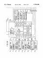
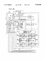
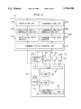
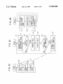
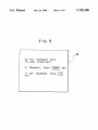
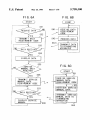
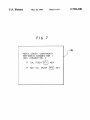
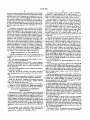
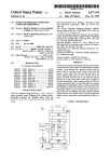
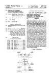
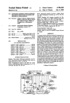
USOO5758300A
United States Patent 1191
[11]
Patent Number:
Abe
[45]
Date of Patent:
[54] DIAGNOSIS SYSTEM FOR MOTOR
4,831,560
4,857,716
VEHICLES AND THE METHOD THEREOF
[75] Inventor: Kunihiro Abe. Higashi-Murayama.
Japan
[73] Assignee: Fuji Jukogyo Kabushiki Kaisha.
Tokyo. Japan
5,758,300
May 26, 1998
5/1989 Zaleskj ............................. .. 364/5510]
8/1989 Gombnch eta],
.... .. 235/462
5,029,183
7/1991
5,072,391
12/1991
Tymes
. . . . . . .. . . .
Abe ......... ..
5,289,378
5,400,018
2/1994 Miller et al. ..
3/1995 Scholl et a1. ..
5.442553
8/1995
. . . . . . . . ..
364/424.05
340/82554
Panillo ..................... .. 364/424.04
5,465,207 11/1995 Boatwrightet a1.
5,541,840
375/1
. 364/42404
364/42401
7/1996 Gume et a1, ..................... .. 364/42403
FOREIGN PATENT DOCUMENTS
[21] Appl. No.: 902,643
Jul. 30, 1997
[22] Filed:
1136045 5/1989
1313773 12/1989
Related US. Application Data
.Tapan.
Japan,
Primary Examiner—Michael Zanelli
Attorney, Agent, or Firm-Martin A. Farber
[63]
Continuation of Ser. No. 444,697, May 19, 1995, aban
doned.
[30]
Foreign Application Priority Data
Jun. 24, 1994
11111.24, 1994
[JP]
[JP]
[57]
ABSTRACT
A Wireless communication unit is built in a portable type
Japan .................................. .. 6-143594
Japan .................................. .. 6-143595
diagnosing apparatus and an external computer respectively.
The portable type diagnosing apparatus reads data from an
electronic control unit of a vehicle and sends the data to the
[51]
[52]
[58]
Int. Cl.6 .................................................. .. G01M 17/00
us. Cl. ............................................... .. 701/33; 701/35
Field of Search ................... .. 364/424.034. 424.037.
364/424.038. 424.04. 551.01; 73/116. 117.2.
117.3
external computer by wireless. The external computer con
ducts miscellaneous calculations based on the data and
displays the result of the calculations on a display of the
external computer or analyzes failures of the vehicle in a
running state. Further. when service manuals are needed.
according to a command from the portable type diagnosing
References Cited
156]
U.S. PATENT DOCUMENTS
4,6m,127
7/1986 Neely et a1. .......................... .. l79/2A
4,796,206
l/1989 Boscove et a1, ................. .. 364/551.01
apparatus. they are sent from the external computer and
displayed on a display of the portable type diagnosing
apparatus.
5 Claims, 8 Drawing Sheets
CD-ROM
DR IVE
55
911i
J
F1
//SEND
?bmmcclcx
37
Enema
‘EHEELEJE
mnwnm I
manor
1
4,551,,“
US. Patent
May 26, 1998
5,758,300
Sheet 1 0f 8
[/6
CD-ROM
DRIVE
55
PRN
54
F2 \
F1:\\
“éébbmd
/SEND
@[EEHEE]
@E1EIEE]
37
@EHEHZHZ]
@[IHZHECR
41’:::]J\ENT
US. Patent
A
May 26, 1998
Sheet 3 of 3
I
!
i
i
i
I
I
I
I
I
\ ! »[
L.
I/D INTERFACE
._II_I~._ _-_ ....... _._J5 ____ _.
39
(15)‘ X5
J
!
I
!
5
OUTPUT CKT. “45 I
TR K
K
TC I
0 DISPLAY @EXRD i
i
GK
U
N
56A‘
J
'-- ------- --~ --------- --'
6L
-
3T
5,758,300
I
COMMUNICATION
I
CONTROL cm.
I
f
l
+
I
.
i69c RECEIVING
TRANSMITTING 68a!
I ‘\ DATA BUFFER
i'
I
I
RECEIVING
DATA BUFFER r’
I
TRANSMITTING
!69b DATA
I
I
‘\DEMODULAT I 0N
CKT.
DATA
MODULATION
CKT.
!
I
W951
RECEIVING
:
CKT.
.
I
i
68bi
,1
i
I
I
I
TRANSMITTING 38%I
OKT.
____________ _.__ _.__._._._.i
I l
US. Patent
May 26, 1998
70
F I G. 3
[> ‘J
69a
\\
I
68c
TRANSMITTING CKT. /-/
RECEIVING CKT.
V
A
6%
¥\ RECEIVING DATA
TRANSMITTING DATA
DEMODULATION CKT.
690
I“
5,758,300
Sheet 4 of s
MODULATION CKT.
I
I
RECEIVING DATA
TRANSMITTING DATA
BUFFER
BUFFER
\68B
686
_,
F
‘
A
COMMUNICATION CONTROL CKT.
642
53
54
OUTPUT
CKT.
I
“67
52 @V 63
\
L3
I
I
I
A
V
V
l/O
/\
61
56%
98b
’
U
:> ROM “58
CPU c :> RAM W59
8
62
57
HD cm 4
~i> TROLLER
60f
S
A
“D0
55
US. Patent
May 26, 1998
Sheet 6 of 8
5,758,300
FIG.5
36
DO YOU TRANSMIT DATA
TO HOST COMPUTER ?
IF TRANSMIT, PUSH
SEND
IF NOT TRANSMIT, PUSH
KEY
KEY
F1
US. Patent
May 26, 1993
Sheet 7 0f 8
5,758,300
F I G. 6A
F I G. 68
( START )
( START )
V
S41~
RECEIVE DATA
REQUIREMENT
/ CODE
I
TRANSMIT DATA
/
$42~
PROCESS DATA
REQUIREMENT CODE
I
8431
TRANSMIT DATA
/ To DIAGNOSING
APPARATUS
I__
DISPLAY DATA
'
S35
SERVICE
FIG. 6C
MANUAL DATA
REQUOI RED
I
START
7
YES
/
M???g'?'g?ERI/ICE
A
REQUIREMENT QQDE
I
S51
,
H
RECEIVE SERVICE
MANUAL DATA
a
/" REQUIREMENT CODE
¢
852
f
RETRIEVE SERVICE
MANUAL DATA
I
TRANSMI T SERVICE
MANUAL DATA TO
2 DIAGNOSING
APPARATUS
DISPLAY SERVICE
MANUAL
——————I
1538
_
_. I
,1
853
US. Patent
May 26, 1998
Sheet 8 of 8
5,758,300
FIG.?
I36
NEXT, CHECK CONTINUITY
BETWEEN CONNECTOR 1
AND CONNECTOR
IF OK, PUSH
2.
F1
IF NOT OK, PUSH
KEY
F2
KEY
5.758.300
1
2
DIAGNOSIS SYSTEM FOR MOTOR
VEHICLES AND THE METHOD THEREOF
according to the data or speci?cations displayed on the
display of the diagnosing apparatus. The ROM cartridge can
be selected in accordance with the diagnosis mode or the
vehicle model.
RELATED APPLICATION
However. in this type of diagnosing apparatus. it is
troublesome and inefficient to replace the cartridge each
time when the diagnosis mode is changed or when the
vehicle being subjected to diagnosis is changed from one to
the other model. Further. the capacity of a sheet of ROM
cartridge is not enough to store manuals. data and speci?
cations covering all diagnosis modes. To solve this problem
This application is a continuation of my application Ser.
No. 08/444.697. ?led May 19. 1995. now abandoned.
BACKGROUND OF THE INVENTION
1. Field of the Invention
The present invention relates to a diagnosis system and a
method for a motor vehicle and more particularly to a
of capacity. for example. a CD-ROM or the like can be
portable type diagnosing apparatus utilizing an external
considered as an alter native but in this case there is a
computer.
problem in that the size of the apparatus inevitably becomes
large. and as a result the portability of the diagnosing
apparatus is lost.
A Japanese Unexamined Patent Application. Toku-Kai
Hei No. 1-136045. for example. discloses a technique in
which the abovementioned ROM cartridge is connected to
2. Prior Arts
Motor vehicles in the state of the art have a control system
which is sophisticatedly computerized and. therefore. when
they are'checkod for diagnosis. it has been inevitable to use
a portable type diagnosing apparatus ‘(a so-called hand-held
computer) capable of being connected to the vehicular
20
control system so as to check input/output signals thereto
and therefrom.
an external computer so as to expand the capacity of the
diagnosing apparatus by reading the contents of the service
manual stored in the external computer.
This diagnosis system also has the same disadvantages as
Generally in this portable type diagnosing apparatus.
since its design philosophy is stressed on portability and
those described before because it still needs a cable com
wide use in order that a service mechanic can make a brief 25 municating the diagnosing apparatus with the external com
check on miscellaneous maintenance items while he is
riding on a vehicle. there are such problems that the amount
puter.
of displayed information is limited and it has no capability
for calculating or analyzing detected data due to its small
SUMMARY OF THE INVENTION
Accordingly. the present invention is intended to obviate
the abovedescribed problems and disadvantages of the
capacity.
For solving these problems. for example. Japanese Unex
amined Patent Application. No. Toku-Kai-Hei 1-313773
discloses a diagnosis system in which the portable type
known diagnosis system and it is summarized as follows.
It is an object of the present invention to provide a
However. the diagnosis system according to this prior art
portable type diagnosing apparatus capable of diagnosing.
has a disadvantage in that it is inconvenient to handle the
calculating and analyzing in a running condition of the
vehicle.
Another object of the present invention is to provide a
portable type diagnosing apparatus capable of calculating
diagnosing apparatus can be connected with an external
35 and/or analyzing detected data without using a connecting
computer through a connecting cable so as to transmit
cable.
information which is unable be processed by this apparatus
to the external computer for processing.
A further object of the present invention is to provide a
system because it needs a cable communicating the portable
type diagnosing apparatus with the external computer.
although the diagnosis system enables more sophisticated
portable type diagnosing apparatus capable of displaying
' diagnoses. That is. a service mechanic must Wire between a
work ?eld where the diagnosing apparatus is located and a
station where the computer is located. This may bring
troubles or inconveniences during service works in the work
?eld.
related service information including service manuals. ser
45 vice bulletins and parts lists on a real-time base when
diagnoses are performed
The diagnosis system according to the present invention
comprises: data reading means provided in a portable diag
Furthermore. generally in diagnosing the vehicle. diag
nosing apparatus for reading data from an electronic control
noses are frequently performed in a running state of the 50 unit; ?rst data displaying means provided in the portable
vehicle in order to con?rm failures by reproducing them in
diagnosing apparatus for displaying the data: wireless data
transmitting means provided in the portable diagnosing
apparatus for transmitting the data by wireless; wireless data
an actual use. In this case. the abovementioned diagnosis
system is almost of no use because of the existence of the
cable connecting the diagnosing apparatus and the external
computer.
55
Next. when the service mechanic attempts to check the
receiving means provided in an external computer for
receiving the data by wireless; data processing means pro
vided in the external computer for processing the data and
control system of the vehicle. he has to proceed diagnoses in
outputting the processed data; and second data displaying
accordance with a service manual. In this case. the service
means provided in the external computer for displaying the
manual should be prepared nearby the service mechanic.
data.
because. while referring to the service manual. he must
The diagnosis system further comprises: data requiring
compare the miscellaneous data acquired through the diag
command inputting means for inputting a data requiring
command to the portable diagnosing apparatus; ?rst wireless
nosing apparatus with the data or speci?cations described in
the service manual to check an existence or non-existence of
failures and to identify whae failures are located.
Some of recent diagnosing apparatuses can display the
contents of the service manual which are stored in a ROM
cartridge inserted therein so as to proceed a diagnosis work
65
data transmitting means provided in the portable diagnosing
apparatus for transmitting the command by wireless; second
wireless data receiving means provided in the external
computer for receiving the command by wireless; a data
storing medium provided in the external computer for stor
5.758.300
3
4
ing service data; retrieving means provided in the external
computer for retrieving the service data from the data storing
The engine control unit 2 comprises a CPU 3. a ROM 4.
a RAM 5. an input interface 6. an output interface 7. a
bu sline through which these devices are connected with each
other. a constant voltage circuit 8 and a driver circuit 9.
The data inputted via the input interface 6 are a coolant
medium based on the command and outputting the service
data; second wireless data transmitting means provided in
the external computer for transmitting the service data by
wireless; ?rst wireless data receiving means provided in the
temperature signal Tw detected by a coolant temperature
portable diagnosing apparatus for receiving the service data
sensor 10. a lean/rich signal A. of the air-fuel ratio detected
by an O2 sensor 11. an intake air amount signal Q measured
by an intake air amount sensor 12. an ON/OFF signal SW“
of an air-conditioner switch 13. a vehicle speed signal S
detected by a vehicle speed sensor 14. an ON/OFF signal
by wireless; and ?rst data indicating means provided in the
portable diagnosing apparatus for indicating the service
data.
According to those means thus constituted. the portable
type diagnosing apparatus reads data from the electronic
SW, of an idling switch 15. a throttle opening angle signal
control unit installed on the vehicle and the data are trans
mitted to the external computer through a wireless commu
Tr? detected by a throttle opening angle sensor 16. an
ON/OFF signal SW" of a neutral position switch 17. an
nication unit built in the portable diagnosing apparatus and
the external computer respectively. The external computer
receives the data transmitted from the portable diagnosing
apparatus and performs miscellaneous processes with
engine speed signal N detected by an engine speed sensor 18
respect to the data. Those processed data are displayed on
the CPU 3. miscellaneous control variables such as a fuel
the display of the external computer. Further. the diagnosis
system according to the present invention. the portable type
diagnosing apparatus is capable of sending a command to
the external computer by wireless and receiving miscella
neous service information from the external computer by
injection pulse width. an ignition timing and the like are
and the like.
These input data are stored in the RAM 5 temporarily and
are used for the calculation of control variables. That is. in
wireless. Received service information can be displayed on 25
the display of the portable type diagnosing apparatus.
BRIEF DESCRIPTION OF THE DRAWINGS
calculated based on these data and control signals corre
sponding to these control variables are outputted from the
output interface 7 to the driver circuit 9 at a specified timing.
Then. these control signals are transformed into driver
signals in the driver circuit 9. Then these driver signals are
outputted to a canister control system 19. an EGR actuator
20 for controlling an EGR amount. an idling control actuator
21 for controlling an idling speed. an ignition coil 22 for
energizing an ignition signal on a spark plug. a fuel injector
23 for metering and injecting a speci?ed amount of fuel and
A speci?c embodiment of the present invention will be
described. with reference to the accompanying drawings. in
which:
FIG. 1 is a schematic diagram showing a diagnosis system
other device to control the engine at an optimum condition
in any operational area.
Next. the portable type diagnosing apparatus A will be
according to the present invention;
and an electronic control unit of a vehicle according to the
described.
The portable type diagnosing apparatus A has a display 36
and a key board 37. Further. inside the apparatus. a diagnosis
present invention;
control section 38 composed of a CPU 42. a RAM 43. an 110
FIG. 2. comprising FIGS. 2A and 2B. is a block diagram
showing the relationship between a diagnosing apparatus
35
(input and output) interface 44. a busline through which
FIG. 3 is a block diagram in a host computer according to
these are connected with each other and an output circuit 45.
and an electric power source circuit 39 are disposed as
shown in FIG. 2.
Further. the diagnosis control section 38 is connected to a
ROM cartridge 41 through a connector 40 for the purpose of
a wide use. i.e.. various diagnosis items and different vehicle
the present invention;
FIGS. 4A. 4B and 4C constitute a ?owchart showing a
data communication process according to the present inven
tion;
FIG. 5 is a drawing showing an example of a message to
be displayed on the portable type diagnosing apparatus;
models. The ROM cartridge 41 contains a ROM 410
wherein diagnosis items and diagnosis programs for differ
FIGS. 6A. 6B and 6C constitute a ?owchart showing a
data communication process according to another embodi
ment of the present invention; and
ent vehicle models are memorized.
Further. diagnosis mode signals which are inputted from
FIG. 7 is a drawing showing an example of a message to
be displayed on the portable type diagnosing apparatus
according to another embodiment of the present invention.
DETAILED DESCRIPTION OF PREFERRED
EMBODIMENTS
Referring now to FIG. 1. the diagnosis system according
to the present invention comprises a portable type diagnos
ing apparatus (a so-called hand-held computer) A and a host
computer B. This diagnosis system is employed in a service
shop to diagnose an electronic control unit D installed on a
vehicle C based on the data read from the electronic control
unit D through an adapter harness 32 communicating an
input/output connector 31 of the portable type diagnosing
50
the key board 37 enter into an input port of the I/O interface
44 and further. signals from the engine control unit 2 are
inputted to this input port through the output interface 7. The
55
output port of the I/O interface 44 is connected to the input
interface 6 of the engine control unit 2 and to the display 36.
The power source circuit 39 of the diagnosis control section
38 is connected to the battery V,9 of the vehicle C through
the adapter harness 32.
On the other hand. as shown in FIG. 1. the host computer
B comprises a control unit 51 wherein miscellaneous con
trols and calculations are carried out. a display 52 for
displaying diagnosis data. collected data. analysis data and
other data. and a key board 53 through which command data
are inputted to the control unit 51. Further. the control unit
apparatus A with a connector 2a of the electronic control unit
51 is connected with peripheral devices such as a printer 54
D.
As an example of the electronic control unit D in this 65 and a CD-ROM drive 55.
Referring to FIG. 3. an arithmetic and control section 56
embodiment. an engine control unit 2 for controlling an
in the control unit 51 comprises a CPU 57. a ROM 58. a
engine will be described by referring to FIG. 2.
'5 .75 8.300
5
6
RAM 59. a HD (hard disc) controller 60 and an IIO interface
61 connected to these devices through a bus line. The I/O
interface 61 is connected with the abovementioned periph
eral devices and the HD controller 60 is connected with a
HDD (hard disc drive) 62 containing a hard disc on which
In the diagnosing apparatus A. when at a step S2 it is
judged that the data have been received. the program goes to
a step S3 where the data are subjected to the miscellaneous
processes such as a transformation into physical quantity.
Then. at a step S4 those processed data are displayed on the
display 36 of the diagnosing apparatus A. For example. in
case of the fuel injection pulse width. a fuel injection pulse
duration time is displayed in ?gures on the display 36.
the control program and the ?xed data are stored. Further.
the CD-ROM drive 55 drives a CD-ROM 63 storing mis
cellaneous electronic data such as work manuals and the
like.
The diagnosing apparatus A and the host computer B are
respectively equipped with a data communication unit 66A.
66B as transmitting and receiving means for performing data
communication by wireless. As shown in FIG. 2 and FIG. 3.
the output port of the I/O interface 44. 61 of the control
section 38. 56 is respectively connected with an output
circuit 45. 64 for outputting the data processed in the control
section 38. S6 to the data communication unit 66A. 66B
respectively. Further. the receiving data from the commu
nication unit 66A. 66B are inputted to the input port of the
I/O interface 44. 61 respectively.
It)
Next. at a step S5 it is judged whether or not those data
should be sent to the host computer B. In this embodiment.
for example. such a message as shown in FIG. 5 appears on
the display 36. If the mechanic wants to send. he pushes a
[SEND] key and if does not he pushes a [F1] key. In case of
pushing the [F1] key. the data are not sent and accordingly
the program returns to the step S1. In case of pushing the
[SEND] key. the program goes to a step S6 where the data
are sent to the host computer B and after that the program
returns to the step S1.
20
Returning to the step S1. the command already inputted is
executed automatically and therefore updated information is
always displayed on the display 36 of the diagnosing appa
On the other hand. the data communication unit 66A. 66B
ratus A. Further. while the sending command is outputted to
respectively comprise a communication control circuit 67.
67 for sending and receiving the data between the data
communication unit 66A and 66B. a transmitting data buifer
68a, 68a for storing the transmitting data outputted from the
communication control circuit 67 temporarily. a transmitting
data modulation circuit 68b, 68b for modulating the trans
mitting data into signals ?t for the data transmission and a
transmitting circuit 680, 68c for transmitting the modulated
the host computer B. the data are continued to be sent to the
host computer B in time series. When a new command is
transmitting data to the data communication unit 66A. 66B
respectively through an antenna 70. 70 by wireless. a
25
inputted or a resetting operation is made. the data sending
from the diagnosing apparatus A to the host computer B is
also reset.
In the diagnosing apparatus A. the data to be sent are
outputted from the output circuit 45 of the diagnosis control
30
section 38 to the communication control circuit 67 of the
data communication unit 66A. The data are stored in the
buffer 680 temporarily and then the data are sent to the host
computer B through the antenna 70 by wireless after being
receiving circuit 69a for receiving the transmitting data
modulated in the n’ansmission data modulation circuit 68b.
In the host computer B. the data sent from the diagnosing
35
?t for the processing in the control section 38. S6 and a
apparatus A are received by the receiving circuit 690 of the
receiving data buffer 690, 690 for storing the demodulated
data communication unit 66B and stored in the receiving
data buffer 69c temporarily after being demodulated in the
receiving data temporarily.
receiving data demodulation circuit 69b. Then. the data are
Next. an exemplary procedure for communicating
inputted to the arithmetic and control section 56 of the host
between the engine control unit 2. the portable type diag
computer B through the communication control circuit 67.
nosing apparatus A and the host computer B will be
When the data are inputted to the arithmetic and control
described according to a ?owchart in FIGS. 4A. 4B and 4C.
section 56. in the host computer B. at a step S21 the data are
Here. FIG. 4(A) shows steps to be taken in the portable type
inputted and at a step S22 the data are subjected to miscel
diagnosing apparatus A. FIG. 4 (B) does steps to be done in
the engine control unit 2 and FIG. 4 (C) does steps to be 45 laneous processes such as being aggregated. calculated or
statistically processed. Then at a step S23 the results of the
done in the host computer B.
processes are displayed on the display 52 and the process
First. the service mechanic riding on the vehicle C sub
through the antenna 70. 70. a receiving data demodulation
circuit 69b for demodulating this receiving data into signals
jected to diagnoses connects the portable type diagnosing
returns to the step S21.
apparatus A to the engine control unit 2 of the vehicle C
Thus. the host computer B can diagnose failures sophis
ticatedly by aggregating or analyzing the data which can not
through the adapter harness 32.
be processed in the portable type diagnosing apparatus A.
Then. the service mechanic inputs an item of the data to
be read out or the data to be detected in accordance with an
Further. in this host computer B. since the data are trans
index of the work manual through the key board 37. For
example. if he wants to con?rm a fuel injection pulse
mitted from the portable type diagnosing apparatus A by
Then. at a step S1 a command (item) inputted from the key
board 37 is transfonned into a data requiring code by which
an address of the RAM 5 storing the required data in the
be reproduced more easily. Additionally. since the data can
be sent by wireless. no wire arrangement is needed on the
?oor of the work shop and therefore cables do not hamper
engine control unit 2 is designated and the data requirement
the people coming up and down in the work shop. Further.
in this wireless diagnosis system. since plural diagnosing
wireless. the data can be acquired on a real-time base from
duration (fuel injection pulse width). he inputs F1 2 EN'I‘. 55 the vehicle C in a running condition. As a result. failures can
code is transmitted to the engine control unit 2.
In the engine control unit 2. at a step S11 the data
apparatuses A can be operated simultaneously per one host
computer B. work ef?ciency is largely improved.
requirement code transmitted from the diagnosing apparatus
In the ?rst embodiment described before. the data trans
A is received. At a step S12 the data stored in an address are
read out by retrieving an address corresponding to this data
requirement code and are transformed into a format ?t for
mission is performed only from the portable type diagnosing
the data transmission. Next. at a step S13 the data are
apparatus A to the host computer B.
In a second embodiment mentioned hereinafter. a diag
transmitted to the portable type diagnosing apparatus A.
nosis system capable of communicating mutually between
65
5 .75 8.300
7
8
the diagnosing apparatus and the host computer will be
described. Following explanation is an example of the
processes to be taken in the second embodiment according
to the present invention.
The service mechanic connects the portable type diag
communication control circuit 67 of the data communication
unit 66A and stored in the transmission data buffer 68a
temporarily. After this requirement code is modulated into a
signal fit for the data transmission in the transmission data
modulation circuit 68b, it is sent from the transmission
circuit 68c by wireless through the antenna 70.
This data sent by wireless is received by the receiving
circuit 690 of the data communication unit 66B in the host
computer B through the antenna 70 and is stored temporarily
in the receiving data butTer 690, after being demodulated by
the receiving data demodulation circuit 69b. After that the
nosing apparatusAwith the engine control unit 2 through the
adapter harness 32. Referring to FIGS. 6A-6C. when a
switch (not shown) is turned on. at a step S31 it is judged
whether or not the data are required to the engine control
unit 2. At this moment. a message showing whether or not
the data are required to the engine control unit 2 is displayed
on the display 36 of the diagnosing apparatus A. He inputs
a command (a [1] key if required and a IO] key if not
data are inputted to the arithmetic and control unit 56 of the
host computer B through the communication control circuit
67.
When the service manual requirement code is received at
a step S51 in the host computer B. at the next step $52 the
object service manual is retrieved. In the CD-ROM 63 of the
host computer B various service manuals are stored. When
required).
If “data required" is chosen. the program goes to a step
S32 where the command corresponding to the kind of data
is inputted through the key board 37. For example. in case
where the data of the fuel injection pulse duration time (fuel
injection pulse width) are needed. he inputs F1 2 ENT. Then.
a requirement of the service manual is transmitted from the
diagnosing apparatus A. in the host computer B the object
service manual is searched by driving the CD-ROM drive
the above command is converted into a data requirement
code by which the address of the RAM 5 storing the subject
data is designated and is transmitted to the engine control
unit 2.
On the other hand. if “data not required” is chosen. the
program skips to a step S35.
When “data required” is chosen at the step S31 and the
data requirement code is transmitted at the step S32. at a step
S41. in the engine control unit 2 the data requirement code
is received. Further. at a step S42 an address corresponding
to the data requirement code is retrieved. the data stored
therein are read out and processed into a format ?t for the
data transmission. At a step S43 the processed data are sent
back to the diagnosing apparatus A.
In the portable type diagnosing apparatus A. at a step S33
when it is judged that the data has been sent from the engine
control unit 2. the program steps to a step S34 where the data
55. The service manuals may be memorized in an internal
memory. a hard disc or other storage medium retrieved by
peripheral devices.
25
That is to say. as illustrated in FIG. 3. the service manual
data are sent to the data communication unit 66B through the
communication control circuit 67 and stored temporarily in
the transmission data buffer 68a. Further. these data are sent
35
themselves. the calculated data or the data converted into
service manual data are stored in the RAM 43 and at the next
step S38 they are displayed on the display 36. Then the
program returns to the step S31.
Here in this step S35. for example. it is judged whether or
45
required. however information required to be sent from the
host computer B may be any information other than the
service manual. The information required here includes a
service manual. a service bulletin. a parts List and other 50
information associated with service work. In this case a
message whether or not a service manual is required is
indicated on the display 36. The mechanic inputs a com
The service mechanic manipulates the key board 37 of the
diagnosing apparatus A according to an instruction in the
service manual shown in FIG. 7 and performs various
diagnoses works such as reading the necessary data in the
engine control unit 2. displaying the data on the display 36.
checking whether or not the obtained data are proper by
comparing them with the criteria of the service manual and
inputting measured values to the key board 37.
Thus. in the second embodiment according to the present
invention. since the service manual data can be read in a
SS
remote place whenever needed. the diagnosis and mainte
nance works become more convenient and more eflicient.
In a case where it is judged that the service manual is not
required. the program returns to the step S31 in which a new
command waits for being inputted. On the other hand. in a
case where it is judged that a service manual is required. the
program goes to a step S36 where a command requiring the
service manual is inputted through the key board 37 and the
command is sent to the host computer B by wireless after
being converted into a service manual requirement code. At
the next step S37 the program waits for the service manual
being sent from the host computer B.
The service manual requirement code is sent from the
output circuit 45 of the diagnosis control section 38 to the
66A through the antenna 70 and are stored temporarily in the
that the object service manual data have been received. the
The program goes to a step S35 from the steps S31 or S34.
mand (a [1] key if required and a [0] key if not required)
according to the message.
from the transmission circuit 68c by wireless through the
antenna 70. after being modulated into signals ?t for the data
transmission.
The data sent by wireless. as shown in FIG. 2. are received
by the receiving circuit 69a of the data communication unit
receiving data buifer 690 after being demodulated by the
receiving data demodulation circuit 69b.
Further. in the diagnosis control section 38 of the portable
type diagnosing apparatus A. at a step S37 when it is judged
physical quantity are displayed on the display 36. For
example. if the data of the fuel injection pulse width have
been required at the step S32. the fuel injection pulse
duration time is displayed in ?gures on the display 36.
not a service manual is required to be sent from the host
computer B. In this embodiments a service manual is
Further. at a step S53 the object service manual retrieved
at the step S52 is sent back to the diagnosing apparatus A.
In this embodiment. as an example of the electronic
control system installed on the vehicle. the engine control
unit 2 has been described. however the electronic control
system is not limited to the engine control unit. and for
example. other electronic control units such as a transmis
sion control unit. a brake control unit. automatic cruise
control unit. an air-conditioner control unit and the like. may
be objects of diagnoses.
65
Further. in this embodiment the service manuals are
stored in the host computer. however they may be stored in
another external computer forming a computer network.
5.758.300
10
9
of one possible command the wireless communication
with said external computer to obtain only an object
In summary. according to the present invention. since the
portable type diagnosing apparatus can not only read data
from the electronic control unit of the vehicle but also send
the data to the external computer from a remote place or
part of said service-related information relating to said
obtained operational data. and a display for sequen
tially indicating said obtained data and said obtained
from the vehicle in a running state by wireless and display
the data processed in this external computer on the display
of the portable type diagnosing apparatus. more extended
service-related information.
2. The system according to claim 1. wherein said medium
of said external computer provides service related informa
tion in the form of service manual data.
3. The system according to claim 1. wherein said medium
of said external computer provides service-related informa
tion in the form of service bulletins.
4. The system according to claim 1. wherein said medium
and more ef?cient diagnosis works are available. Further.
since service related information. such as service manuals
and service bulletins can be displayed on the display of the
portable type diagnosing apparatus whenever needed. such
troublesome and time-consuming work in that the service
mechanic goes back to an o?ice each time when he wants to
examine service manuals or service bulletins can be saved.
of said external computer provides service-related informa
tion in the fonn of parts lists.
While the presently preferred embodiments of the present
5. Amethod of diagnosing failures of a vehicle having an
invention have been shown and described. it is to be
understood that these disclosures are for the purpose of
illustration and that various changes and modi?cations may
be made without departing from the scope of the invention
as set forth in the appended claims.
What is claimed is:
1. A diagnosis system for a motor vehicle having an
electronic control unit. comprising:
a diagnosis apparatus selectively connected to said elec
tronic control unit through a wire harness for
bi-directional communication therebetween; and
an external computer provided to perform wireless com
munication with said diagnosis apparatus. the external
computer having a medium storing service-related
electronic control unit. comprising:
connecting a diagnosis apparatus with said electronic
control unit;
inputting a command through a keyboard of said diagno
sis apparatus to obtain operational data of said elec
tronic control unit by means of bi-directional
communication. said obtained operational data being
25
tional data from an external computer by means of
information;
wireless communication between said diagnosis appa
ratus and said external computer. said obtained object
wherein said diagnosis apparatus has a keyboard for an
operator to input a command. a microprocessor respon
sive to said input command for performing the
bi-directional communication with said electronic con
indicated on a display of said diagnosis apparatus; and
inputting a next command upon selection of one possible
command through said keyboard on said diagnosis
apparatus to obtain only an object part of service
related information relating to said obtained opera
service-related information being subsequently indi
35
cated on said display for the guidance of effective
diagnosis of said obtained data.
trol unit to obtain operational data of said electronic
control unit and additionally performing upon selection
*
*
*
*
*