1
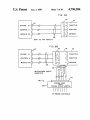
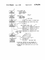
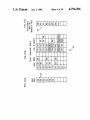
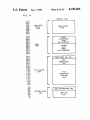
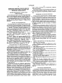
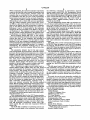
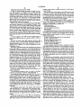
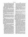
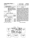
United States Patent [191
[11]
[45]
Boscove et a1.
[54] COMPUTER ASSISTED VEHICLE SERVICE
FEATURING SIGNATURE ANALYSIS AND
ARTIFICIAL INTELLIGENCE
[75] Inventors: Joseph A. Boscove, Highland Beach;
Hobart L. Kurtz, Boca Raton, both of
Fla.; Jeffrey E. Prince, William P.
Wiegand, both of Birmingham,
Mich.
[73] Assignee:
Book: “Electronic Engine Controls”, Chilton Book
'00.,"1'9‘85 'Frontispiece, cdntents, pp; 33-41, 239-259,
274, 275.
Article: “Speci?c Cell Location Assembly for Dis
plays”, R. V. Ballou et a1, IBM Technical Disclosure
Bulletin, Feb. 1985, vol. 27, No. 9, pp. 5104-5106.
Article: “Computerized Diagnostic Tester at Hand”,
Electrical World, Aug. 1, 1975, pp. 36-38.
Testing and Diagnosis”, T. A. Cross, IEE Conference
Jul. 69, 1976, London, England, pp. 152-159.
Primary Examiner—Gary Chin
International Business Machines
[21] Appl. No.: 869,534
Assistant Examiner—Thomas G. Black
Attorney, Agent, or Firm--D. Kendall Cooper; Richard
A. Tomlin
Jun. 2, 1986
[51]
[52]
Int. Cl.‘ ..................... .. G06F 11/32; G06F 15/20
US. Cl. ........................ .. 364/551.01; 364/43l.0l;
[58]
Field of Search ................. .. 364/550, 551, 431.01,
73/116
364/424; 73/116, 117.3
[56]
Jan. 3, 1989
. Article: “A Digital Electronic System for Automobile
Corporation, Armonk, NY.
[22] Filed:
4,796,206
Patent Number:
Date of Patent:
References Cited
U.S. PATENT DOCUMENTS
[57]
ABSTRACT
A computer based technician terminal is connected to a
vehicle being serviced using an assembly line data link
(ALDL) connection from an on-board computer. The
data link provides status information and fault codes.
The technician is led through various procedures. Dur
ing set up, the technician connects an ALDL cable from
4,375,672
3/1983
Kato et al. ........................ .. 364/551
the terminal to the vehicle, the vehicle indenti?cation
number (VIN) is entered and vehicle options are identi
?ed. A fault detection procedure (FDP) in the terminal
detects vehicle malfunctions by interrogating data re
ceived (via the ALDL) from the on-board computer. A
4,404,639
9/1983
McGuire et al. ..
....... .. 364/551
fault analysis procedure (FAP), using the fault codes
4,418,388 11/1983 Allgor et a1. ..... ..
364/43l.01
4,441,359 4/1984 Ezoe ........................ .. 73/117
from a table as arguments, does a sequential compare
4,125,894 11/1978
Cashel et a1. ..................... .. 364/442
4,270,174 5/1981 Karlin et a1.
4,295,363
10/ 1981
364/551
Buck et al. . . . . .
. . . . . . .. 73/117.3
4,476,531 10/1984 Marino et a1. ..
4,649,515 3/1987 Thompson et a1.
4,694,408
9/1987
364/431.0l
.. 371/15 X
Zaleski .............................. .. 364/551
against the contents of a fault analysis table containing
fault codes. In a fault sequencing procedure (FSP), for
each fault code passed by the PAP, there is a list con
taining the name(s) of one or more isolation procedures.
A fault isolation procedure (FIP) is provided for electri
OTHER PUBLICATIONS
Booklet: “The Guide” (Personal Computer), vol. IV,
1985, International Business Machines Corp. Front &
Back Covers, pp. 8, 10, 11, 31, 34, 36.
cal or electronic components on the vehicle to perform
a complete test of the related part using a multifunction
Book: “Programmer’s Guide to the IBM PC”, Peter
test probe. Fault repair procedures guide the technician
through the proper steps to accomplish the repair, re
placement or adjustment required.
Norton, 1985, Microsoft Press, Contents, pp. 5, 6, 7, 12,
42-44, 68, 102-106, 130, 143, 144.
6 Claims, 10 Drawing Sheets
COMPUTER COMMAND CONTROL DIAGRAM
CRANK POS
ELECTRONIC CONTROL MODULE
I31
AIR
CONDITIONING
CLUTCH
SYSTEM
CONTRm.
THROTTLE
POSITION
SENSOR
SWITCH (ES)
BAROMETRIC
SENSOR
I16
TRANSMISSION
CONVERTER CLUTCH
DISTRIBUTOR
3 -WAY
CATALYTIC
CONVERTER
EXHAUST SYSTEM
US. Patent
Jan. 3, 1989
Sheet 1 of 10
4,796,206
FIG. 1
VEHICLE
SYSTEM
TECHNICIAN
TERMINAL
-
103
m rn :0 S o m
SUPPORT SYSTEM
j 105
"~1o4
MASTER
DATA BASE
US. Patent
Jan. 3, 1989
Sheet 3 of 10
4,796,206
gm
US. Patent
4,796,206
Sheet 4 of 10
Jan. 3, 1989
FIG. 4
OVERVIEW OF' TECHNICIAN TERMINAL
[151
TOUCH
/i52
AT
CONTROLLER
V/ 512K MEN.
KEYBOARD
PANEL
ALDL AND TOUCH -<->ADAPTER CARD —<—»———
Al-m- E
CABLE
1551
/1ss
PROBE
ADAPTER CARD
_
‘
_"
PROBE-IE
CABLE
160 /
150
ENHANCED COLOR i167
ADAPTER CARD
MEN
142/
as
CUMPACT
168/ PRINTER
1200 BAUD
SERIAL/PARALLEL _,
ADAPTER CARD #2
no’
172/
171/
175/
MODEM
POWER
__
DISK/DISKETTE
ADAPTER CARD
a!
PC
SERIAL/PARALLEL %
ADAPTER CARD #1
0
I
i
CONTROL
UNIT
20MB DISK
1.2MB DISKETTE
174/
' US. Patent
Jan. 3, 1989
Sheet 5 of 10
4,796,206
FIG.5
MACHINE COVER
ALDL CABLE
FIG. 6
PROBE :. SUPPRESSION DEVICE
MACHINE COVER
D
W0" Bum"
f’
‘6°
:
A
|I
|
/'/'1/
. '
we
162
/ (IN
161
J“
163/
T0 (IN-BOARD
T0 omcuosncs
COMPUTER CABLE
CONTROLLER CONNECTOR
CONNECTOR
PROBE CABLE
I US. Patent
hJan.3, 1989
Sheet 6 0f 10
4,796,206
FIG.7
BATTERY CABLE
MACHINE COVER
FIG. I2
MAIN MENU
DIAGNOSTICS
SERVICE MANUAL
VOLT/OHM METER
DYNAMIC DISPLAY
SERVICE BULLETIN
VEHICLE SPECS
INSTRUCTIONS
COMMUNICATIONS
HELP
US. Patent
Jan. 3, 1989
Sheet 7 of 10
4,796,206
FIG. 8A
181
ENGINE 21/_J2/110
A
,,//
M
C
?A
THROTTLE
CONTROL 2 '1J
1/
/F
N
EB
POSITION
MODULE 22 7_|
/f
l’
gR c
sENsOR
180
ECM TO TPS CIRCUIT
FIG. 8B
jug
‘
5181 i176 /114
C’
ENGINE 21 1
I
OJA
I
A
THROTTLE
E B
B
POSITION
6R c
c
SENSOR
N
CONTROL 2 ‘I
//
J
)7
MODULE 22 ‘I_|
//
(;
//
X
180
>
162
INTERPOSER CABLE
INSERTED
~~
_
._
AID‘; A:
16°\
i625”
|
TTTT' ’
y}
PROBVE| 1!:IEAD
CROSS POINT SWITCH
\lllliil
TO PROBE CONTROLS
‘"
US. Patent
Jan. 3, 1989
/10
m
‘—SERVICE
IEIIIILEEE ETII‘AIAS
MANUAL
H
VEHICLE
4,796,206
sELEcT SUPPORT TYPE
PROCEDURE
1
Sheet 8 of 10
-ET0.
SERVICE sET 01>
/
9
|
FG
- 110A 0110A
PROCEDURE
-001111EOT AL01.
I
_
FAULT TABLE
/
FAULT
J
DETECTION
PROCEDURE
15 _>
1
/I6
FAULT
f
TM DETECTS 1 OR MORE FAULTS
104
PLACES THEM 111 FAULT TABLE
063
’
n
ANALYSIS _
PRocEDuRE~
FAULT ANALYSIS TABLE-‘I/VIN
"
20
032
SELECTED
002
002 FAP SEARCHES FOR
052 104
230 FIRST MATCH 111
003 104 010
251 THE EAuLT
041 151
211 ANALYSIS TABLE
[155] FAULT
1
11/
000E
10
U0
FAULT
D04
SEQUENCING
003
PROCEDURE ~
002
001
)4?
SELECTED
FAULT
/
+21
HP 023
HP 109
PROCEDURE
* RETURN CDDE 'REPAIRED' WILL CAUSE RERUNNING THE
EDP TD VALIDATE REPAIR AND CREATE NEW FAULT LIST
* RETURN CODE 'NIF' CAUSES NEXT FLIP IN LIST TO BE
EXECUTED
US. Patent
$w5“3;
Jan. 3, 1989
Sheet 9 of 10
new 2; I;
one So Ia N3
ME:55 E225x3;5
4,796,206
/
2;E3..2z;
E22:E8:32:
S
E
W
3
5
.
.<901
E2..2:0z;
@
as52.
2..25w5.3
sowe.2.
23 25
m1
@@2.20
NMNN?E.2
NZ
@a®@
@2;m35
a:
/
US. Patent
Jan. 3, 1989
Sheet 10 0f 10
4,796,206
FIG.H
MEMORY MAP
512-
—>
500
238'
228:
ASPX'CE
45O_
104K
-
vA
ABLE
§
440
430
420—
EREOE4IS<PACE
V
i
410
400-
USER
PROCEDURE
AREA
390380370360
64K MINIMUM
usER
22%
128K
<
GLOBAL
33o-
DATA
320-
AREA
3i 0-
.
64K MINIMUM
3oo—
290
#
%
280
270260
250-
00c. VIEW FAC. 20K
FEX
ggg-
WORK AREA
22o_
21o
50K
19o
1eo-
FEX SYSTEM
17016o_
210K
1
FEX
OPERATING
,5o_
14o-
"
SYSTEM
130-
140K
12o11o-
‘
‘
1oo—
90
so
70
gg-
DOS EXTENSIONS 22K
40-
SYSTEM AREA
30-
I 70K
2010
o-
<
IBM DOS
48K
L.
1
4,796,206
COMPUTER ASSISTED VEHICLE SERVICE
FEATURING SIGNATURE ANALYSIS AND
ARTIFICIAL INTELLIGENCE
provide semi-automated diagnostic apparatus for vehi
cles, such apparatus incorporating computer diagnos
CROSS REFERENCE TO RELATED
'
2
cants’ system procedures are distinctively different
from those systems.
The primary objective of the present invention is to
tics.
APPLICATION
SUMMARY OF THE INVENTION
In the technique disclosed herein, programs execute
Cross reference is made to the following patent appli
cations, such application having a common ?ling data
on an off-board computer, and by use of visual display,
prompt a technician to change the vehicle’s state. For
and a common assignee with the present application:
US. patent application Ser. No. 06/869,870 ?led June
2, 1986, entitled “Fault Isolation for Vehicle Using A
Multifunction Test Probe” having R. V. Ballou et al as
inventors.
each state change, a sequence of tests are executed com
paring information in data streams from a vehicle on
board computer against known good parameters or
15
signatures. The signature analysis includes interrogation
PRIOR ART REFERENCES
The following prior art references are of interest and
are referred to in the speci?cation. The ?rst four refer
ences are speci?cally incorporated by reference herein.
parameters.
1. Booklet: “The Guide” (Personal Computers), Vol
ume IV, 1985, International Business Machines Corpo
ration. Front and back covers, Pp. 8, l0, ll, 31, 34, 36.
2. Book: “Programmer’s Guide to the IBM PC”,
Peter Norton 1985, Microsoft Press, Contents, Pp. 5, 6,
programs can be executed to provide detection capabil
ity for more vehicle problems, Building on this ability to
detect faults with a computer, the present system design
describes how, by the use of arti?cial intelligence con
7, 12, 42-44, 68, 102-106, 130, 143. 144.
3. Book: “Electronic Engine Controls”, Chilton
Book Co., 1985, Frontispiece, Contents, Pp. 38-41,
239-259, 274-275.
4. Article” “Speciic Cell Location Assembly for Dis
plays” R. V. Ballou et a1, IBM Technical Disclosure
of single parameters and the correlation of multiple
In the service environment, where more time can be
allocated for testing than that allowed at the end of an
assembly line, enhanced versions of the end of line test
25 cepts, a technician terminal can become “smarter” in it’s
ability to diagnose more vehicle problems.
For a better understanding of the present invention,
together with other and further advantages and features
thereof, reference is made to the description taken in
connection with the accompanying drawings, the scope
Bulletin February 1985, Vol. 27, No. 9, Pp. 5104-5106.
of the invention being pointed out in the appended
5. Article: “Computerized Diagnostic Tester at
claims.
Hand”, Electrical World, Aug. 1, 1975, Pp. 36-38.
BRIEF DESCRIPTION OF THE DRAWINGS
6. Article: “A Digital Electronic System for Automo
bile TEsting and Diagnosis”, T.A. Cross, IEE Confer 35 Referring to the drawings:
ence July 6-9, 1976 London, England, Pp. 152-159.
FIG. 1 illustrates a network in which one or more
technician terminals such as that described herein may
BACKGROUND OF THE INVENTION
be connected.
This invention relates to computerized automotive
FIG. 2 illustrates an engine control system for use on
vehicle diagnostic apparatus and more particularly to a 40
a
vehicle
shown in FIG. 1.
more ef?cient apparatus of this nature having improved
FIG. 3 is a perspective view of the technician termi
performance in relation to the diagnostic procedures
nal in a console configuration.
and related computer programs.
FIG. 4 is a block diagram of the major components in
Microcomputers, electronic sensors and other com
the
technician terminal.
45
ponents are incorporated into vehicles to monitor and
FIGS. 5, 6 and 7 illustrate various cables for use with
control engine operations and other functions.
the technician terminal.
The increasing amount of electronic, electrical and
FIGS. 8A and 8B illustrate interposer cable usage in
electro-mechanical content in automobile designs has
conjunction
with the cable of FIG. 6.
created a severe problem for the vehicle servicing envi
ronment. The service tools available for servicing do 50 FIG. 9 illustrates the diagnostic procedures described
herein.
not provide the capabilities needed to diagnose and
FIGS. 10A, B, and C illustrate tables as they are
repair problems which are directly or indirectly related
organized in an alternative diagnostic procedure.
to the electronics. This has resulted in long diagnostic
FIG. 11 shows a typical utilization of the storage in
times, incorrect repairs and multiple service visits for
the same problem.
-
Considering the prior art references noted above,
55 the technician terminal computer, a memory map for
the software execution system.
FIG. 12 shows a main menu screen displayed on a
Reference 1, “The Guide” describes an IBM Personal
Computer AT that is a useful element in the diagnostic
system set forth herein. Reference 2, The Norton book,
illustrates various characteristics of the IBM Personal
FIG. 7)
Computer AT such as programming, the microproces
sor, keyboard, etc. Reference 3, the Chilton book, de
scribes engine control modules and systems that that are
utilized herein. Reference 4, the Ballou et al article,
A technique is described herein which makes use of a
computer based technician terminal that connects to a
technician terminal monitor. (Same drawing sheet as
DETAILED DESCRIPTION
vehicle being serviced using the assembly line data link
describes a representative touch panel that may be used 65 (ALDL). This data link is used by the various vehicle
manufacturers to test the vehicle at the end of the as
in the practice of the invention. References 5 and 6
relate to computer-based diagnostic systems for engines
and are merely representative of prior systems. Appli
sembly lines. It allows an off-board computer to com
municate with the computers on-board the vehicle.
3
4,796,206
When commanded, the on-board computer outputs data
frames on the data link which contain information about
the state of the various sensors, switches, relays and
actuators that are controlled by the on-board comput
ers. Included in the data are error codes representing
faults detected and stored by the on-board computers.
The network of FIG. 1 includes a technician terminal
100 interfaced with a vehicle 101 and more speci?cally
with the vehicle computer control system 102. Termi~
nal 100 has a data entry facility and touch interactive/
menu driven display, and also incorporates a computer
such as the IBM Personal Computer AT, Prior Art
References l and 2. A touch panel for the technician
terminal is like that described in the Ballou et al Prior
Art Reference 4. The computer control system 102 is
like the control systems described in the Chilton Prior
Art Reference 3, as further illustrated in FIG. 2 herein.
Service Support System 103, FIG. 1, may support
4
the following components or sub-systems; charcoal
canister purge control 124, AIR Management System
123, idle speed control 132, automatic transmission con
verter clutch 128, distributor 122 ignition timing, EGR
valve control 125, EFE control 130, and the air condi
tioner compressor clutch 131. The CCC ECM is
equipped with a PROM assembly similar to the one
used in the C-4 ECM.
The Air Management System 123 is an emission con
trol that provides additional oxygen either to the cata
lyst or the cylinder head ports (in some cases exhaust
manifold), is composed of an air switching valve and/or
an air control valve, controls the air pump ?ow and is
itself controlled by the ECM 110.
The charcoal canister purge control 124 is an electri
cally operated solenoid valve controlled by ECM 110
and when energized, blocks vacuum from reaching the
canister purge valve. When ECM 110 de-energizes the
purge control solenoid, vacuum is allowed to reach the
vehicle data base. A host computer 105 including a 20 canister and operate the purge valve. This releases the
master data base 104 acts as a service support system
fuel vapors collected in the canister into the induction
interface to the user company headquarters, provides
system.
network management and supplies realtime feedback to
The EGR valve control solenoid 125 is activated by
one or more technician terminals and serve as a regional
manufacturing and engineering groups, for example.
ECM 110. When the engine is cold, the ECM energizes
Alternatively, the technician terminals may be con 25 the solenoid. This blocks the vacuum signal to the EGR
nected directly to the host computer 105 and data base
valve 125. When the engine is warm, the ECM de-ener
104.
gizes the solenoid and the vacuum signal is allowed to
The automotive industry has for the past several
reach and activate the EGR valve.
years incorporated microcomputers, electronic sensors
The Transmission Converter Clutch (TCC) 128 lock
and many electro-mechanical components into vehicle
is controlled by the ECM 110 through an electrical
designs to provide better monitoring and control of the
solenoid in the transmission. When the vehicle speed
engine operations. More electronics are being added to
sensor in the instrument panel signals the ECM that the
provide control for other functions as well. Transmis
vehicle has reached the correct speed, the ECM ener
gizes the solenoid which allows the torque converter to
sion, radio, heat/ ventilation/air conditioners, instru:
ment panels, memory seats and mirrors, etc. are some 35 mechanically couple the engine to the transmission.
examples. Future designs will include ever increasing
amounts of hi-tech features such as cellular radio tele
When the brake pedal is pushed or during deceleration,
passing, etc., the ECM returns the transmission to ?uid
phone, vehicle attitude, collision avoidance, etc.
drive.
FIG. 2 illustrates an engine control system used in
The idle speed control 132 adjusts the idle speed to
General Motors (GM) vehicles since the 1981 model 40 load conditions, and lowers the idle speed under no
year and designated the Computer Command Control
(CCC) System. This system has many components in
load or low-load conditions to conserve gasoline.
common with the earlier GM system referred to as the
(ECM) 110, which is capable of monitoring and adjust
on some engines provides rapid heat to the engine in
duction system to promote smooth start-up and opera
tion.
As noted, the service tools heretofore available for
ing more sensors and components than the ECM used
servicing have not provided the necessary capabilities
Computer Controlled Catalytic Converter (C-4) sys
tem. These include the Electronic Control Module
The Early Fuel Evaporative (EFE) system 130 used
needed to diagnose and repair problems which are di
cally controlled variable-mixture carburetor 112, a
rectly or indirectly related to the vehicle electronics. As
three way catalytic converter 113, throttle position 50 a result there have been long diagnostic times, incorrect
sensor 114 and coolant temperature sensor 115, a baro
repairs and multiple service visits for the same problem.
metric pressure (BARO) sensor 116, a manifold absolute
The technician terminal FIGS. 3 and 4, are designed
pressure (MAP) sensor 117, a “Check Engine” light 120
to overcome these problems and may typically incorpo
on the instrument cluster, and an Electronic Spark Tim
rate the following elements:
ing (EST) distributor 122, which on some engines (tur 55 PC/AT Based Controller
bocharged) is equipped with an Electronic Spark Con
512KB Memory
trol (ESC) that retards ignition spark under some condi
1.2 MB 5.25 Diskette Drive
20MB Fixed Disk Drive
tions (detonation, etc.).
Other components used by the CCC System include
13" Color Monitor
the Air Injection Reaction (AIR) Management System
Infrared (I/R) Touch Panel
123, charcoal canister purge control 124, Exhaust Gas
Communications Card
Recirculation (EGR) valve control 125, engine speed
ALDL Attachment Card & Cables
sensor 129, transmission torque converter clutch sole
Probe Attachment Card & Cables
noid 128 (automatic transmission models only), idle
Printer
speed control 132, and early fuel evaporative (EFE) 65 Mobile Work STation
system 130.
Fault Isolation Repair Procedure Program Executor
The ECM 110, in addition to monitoring sensors and
(FEX) Diagnostic Executive
sending a control signal to the carburetor, also controls
Remote Update Facility
on the 04 system, an oxygen sensor 111, an electroni
5
4,796,206
FEX Development System (FDS)
tional circuits.
The ALDL and touch adapter card 152 located in the
technician terminal reads data presented to the ALDL
connector from the vehicle ECM and formats the data
In FIG. 3, the technician terminal is housed in a con
sole 140 mounted on wheels, such as wheel 141 for
greater mobility. Console 140 has a display monitor 142
integrally incorporated therewith, monitor 142 having
an infrared touch panel on the face thereof. A keyboard,
such as the PC AT keyboard, is incorporated within
drawer 143. The console also has a printer 144. Drawers
145 and 146 are provided for storage, drawer 146 ac
commodating cables, for example.
6
reading, inject source voltage/ ground or verify opera
in a standard manner acceptable to the PC. Card 152 is
programmable and accommodates various wiring con
?gurations, data structures, and line speeds.
A FEX Development System (FDS) is used that
10 involves PC utility programs that run on the IBM PC to
support development of Vehicle Service Procedures.
Examples of the utility programs are:
Table Generator
Procedure Generator
FIG. 4 is an overview of the internal interconnections
and primary elements in the technician terminal._This
includes the PC AT controller 150, infrared touch panel
151 associated with the display monitor 142, an ALDL
and touch adapter Card 152, which besides panel 151
inputs, receives input signals from the on-board ECM
by way of the ALDL cable 153, also shown in FIG. 5.
Service Bulletin Generator
File Utilities
The Fault Isolation Repair Procedure Program Exec
utor (FEX) is the systems control program that operates
the Technician Terminal. The Vehicle Service Proce
5 for interconnection of the technician terminal with the
20 dures operate under control of PBX to perform the
ECM.
following functions:
A probe adapter card 158 receives signals from a
Guide Technician through service procedures
probe cable 160, also shown in greater detail in FIGS. 6
Retrieve and store data
Cable 153 has connectors 154 and 155 as shown in FIG.
and 8.
Execute diagnostic procedures
Build and display panels
IN FIG. 6, probe cable 160 comprises portions 161
and 162 as well as a device 163 for use by the technician
Control Test Probe operations
during diagnostics as more fully described in the co
Control ALDL Interface
pending R. V. Ballou et al patent application cross
In the technique disclosed herein, programs execut
referenced above.
ing on the off-bard computer in the technician terminal
FIGS. 8A and 8B illustrate the attachment of the test 30 140, FIGS. 3 and 4, by use of a visual display, prompt
probe cable 160 to a component. Normally ECM 110 is
the technician to change the vehicle’s state. For each
connected to component 114 by way of cable 180 with
state change a sequence of tests are executed comparing
connector 181. As mentioned, Probe 160 consists of a
information from the data streams against known good
multiple conductor cable attached to the probe control
ler through adapter card 158 and terminated externally
at a zero force insertion type connector 176, shown
diagrammatically in' FIG. 8B. The attachment of the
35
signatures. The signature analysis includes interrogation
of single parameters and the correlation of multiple
parameters.
In the service environment, where more time can be
allocated for testing than that allowed at the end of an
assembly line, enhanced versions of the end of line test
the component connector 176 on one end and a connec 40 programs can be executed to provide detection capabil
tor 177 which mates with the test probe head 163 on the
ity for more vehicle problems. Building on this ability to
other end. This cable is called a vehicle probe interface
detect faults with a computer, the present system design
(V PI). The connector 176 of the VPI cable is inserted in
describes how, by the use of arti?cial intelligence con
line with the component to be tested and the other
cepts, a technician terminal can become “smarter” in it’s
connector 177 is plugged into the probe head.
ability to diagnose more vehicle problems. Also, as
Use of the probe is fully described in the Ballou et a1
de?ned in the Ballou et al patent application a multi
probe to a component to be tested such as throttle posi
tion sensor 114 is accomplished by use of cables having
patent application.
The technician terminal, may for battery checking
purposes, incorporate a battery cable 165, FIG. 7.
function program controlled probe supports fault isola
tion to the component to be replaced, repaired or ad
justed. The system structure defines a hierarchical set of
An enhanced color adapter card 167, FIG. 4, is con 50 programs which utilize the contents of tables that spec
nected to monitor 142 for output of display signals. A
ify what vehicle states to set, which tests to run, which
signatures to use, and what repair actions to take.
printer 168 is driven by way of another adapter card
The technician terminal would usually be incorpo
(#1) designated 169, while a modem 170 and power
rated in the communications network, FIG. 1. The
control unit 171 are connected to controlled 150 by way
network connects all technician terminals to the data'
of adapter card (#2) designated 172. Modem 170 can be
base in the support system 103, FIG. 1, and to the host
an internal modem rather than external as shown. Both
computer 105 which collects statistics on a periodic
a 20 megabyte hard disk ?le 173 and a 1.2 megabyte
basis relative to the repair actions performed on the
?oppy diskette ?le 174 are accommodated by adapter
vehicles, the data being stored in the master data base
card 175.
104. As indicated, the technician terminals may be con
The infrared touch panel and display 142 interface
nected directly to the host via a network. Statistical
with the IBM PC AT electronics for technician input.
analysis programs are used to correlate the readings
The multi-function measurement cables/probes 153,
taken during problem analysis and isolation against the
160 supported by adapter cards 152 and 158 are for use
actual repair actions performed. Based on the results of
by the technician in diagnosing and isolating a vehicle
65 the analysis, the signature tables, the isolation sequence
failure.
tables and the probe test tables are updated to reflect
Functions performed by probe 160 are controlled by
this later level of “learning”. The updated tables are
Vehicle Service Procedures programmed in controller
distributed to all technician terminals over the network.
150 which interactively request the technician to take
7
4,796,206
The network is also used to provide updates of new or
8
In the Fault Sequencing Procedure 20 (FSP), for
each fault code passed by the FAP, there is a list in the
revised programs and display panels.
The system procedure is illustrated in the flow chart
form of tables 21 containing the name(s) of one or more
shown in FIG. 9 and an alternative procedure makes
isolation procedures. These lists are also updated by the
5 host system to reflect the results of statistical analysis of
use of tables shown in FIGS. 10A, B, and C.
The Main Menu Procedure 10 is active whenever the
service histories. Each procedure name in the list repre
terminal is powered on but not in use. It displays the
sents a component that has required a repair action
main menu on the monitor from which the technician
selects the type of support desired. A typical main menu
contains more than one name, they are ordered based
is shown in FIG. 12. (Same drawing sheet as FIG. 7)
upon frequency of cause.
when the related fault code was detected. If the list
This includes Vehicle Service Procedure (V SP) 11
The FSP 20 causes the procedure names at the top of
which leads the technician through the set up steps
the list to execute at the next hierarchical level. The
required for any service. These include:
FAP and FSP procedures in blocks 16 and 20 may be
Validate vehicle power and ground
combined into one procedure, if desired and only one
systems
15 table may be set up to accommodate the data stored in
Connect ALDL cable to the vehicle
tables 17 and 21.
Input the vehicle identi?cation number (VIN)
Identify certain vehicle options
The Fault Detection Procedure 12 (FDP) detects
vehicle malfunctions by interrogating data received (via
The combining of the Fault Analysis Procedure
(FAP) and the Fault Sequencing Procedure (FSP) into
20
the ALDL) from the on-board computer. The data is
read during different vehicle states.
The Fault Analysis Procedure:
1. Sorts the fault codes in the fault table, 15a, FIG.
Ignition on (not running)
Engine cranking
Engine idling
one procedure called the Fault Analysis Procedure
makes use of the tables shown in FIGS. 10A, B, and C.
10A.
25
Engine at 2500 RPM
The data read represents the state of the various
switches, sensors and actuators on the vehicle. The
values read from each of the components are compared
against known good parameters which are unique to the
vehicle under test as identi?ed by the VIN. Values from
the components are correlated to establish that, even
through they are within limits, they are also correct
relative to the state of the vehicle and relative to the
values read from other components having inter-depen 35
2. Searches the fault analysis table 17a, FIG. 10B for
a line where all of the fault codes in that line are
listed in the fault table.
3. When a match is found then the FIPs listed in the
Fault Analysis Table 170 are executed in order,
table 21a, FIG. 10C.
4. Checks to see if it has already executed that FIP. If
it has then that FIP is not executed a second time.
5. Continues to execute the FIPs on matching line in
the Fault Analysis Table 17a until the problem is
?xed or there are no more FIPs to execute.
dencies.
All_ faults detected during this procedure are placed
6. If the problem is found and repaired the control is
passed back to the Fault Detection Procedure 12,
in table 15 and control is passed to the next hierarchical
procedure. Each fault type is de?ned by a fault code.
FIG. 9, so it can recheck for faults.
7. If none of the FIPs listed on the line in the Fault
The Fault Analysis Procedure 16 (FAP), using the
Analysis Table 170 solve the problem then the
fault codes from the tables 15 are arguments, does a
FAP goes to the next line in table and looks for
sequential compare against the contents of the Fault
Analysis Table 17. Each entry in this table contains one
matches (Step 2 above).
Given the faults logged in the Fault Table 15a and the
associated Fault Analysis table 170 the circled FIPs in
or more fault codes. Multiple codes in an entry repre
sent a set that when detected concurrently indicate a 45 FIG. 10B would be executed.
' A Fault Isolation Procedure as at block 22 (FIP) is
specific component malfunction as being the most prob
executed for the electrical or electronic components on
able cause. A different fault code is assigned to each
the vehicle the procedure being selected from the group
code set.
Fault Analysis Table 17 is continuously updated by
of procedures chosen by FSP 20. These procedures
the network host computer and redistributed to all ter 50 perform a complete test of the related part using the
multi-function test probe 160. A complete “black box”
minals in the network on some periodic basis, such as
analysis of the component is performed. There are, of
daily, but overnight so as to have minimum effect on
course, some components such as lights, radios, power
system availability. The updates to the tables are based
windows, door locks, etc. that are not covered by pro
upon statistical analysis of all Service Incident Reports
(SIR’s) that have been stored in the host data base since 55 cedures. Many vehicles already have FIPs which cover
these components. There are also FIPs for non-electri
the last update period. A. SIR is generated and sent to
cal components such as throttle linkages, vacuum hoses,
the host for each repair action performed on a vehicle.
fuel system, etc.
'
Each SIR contains the VIN, detected fault codes, com
This test of components has one of the following
ponent readings and repair action taken. This mecha
nism, over time, increases the probability of finding and 60 results:
The test fails which will cause the FIP to invoke the
correcting the malfunctioning part on the first pass
through the fault analysis table since the table is ordered
proper procedure to guide the technician in the
based on frequency of success relative to the codes.
The search of the table continues until an entry is
found whose fault codes match one or more of those 65
repair, replace or adjustment required. When the
passed by the FDP. The fault code found such as “236”
at block 18 in that entry is passed to the next hierarchi
the FDP to determine if the repair action elimi
nated all the faults found on the initial pass. If not,
then the same scenario is again followed.
cal procedure.
repair action is completed, the same FIP will re-run
the test to validate the fix, then return control to
9
4,796,206
10
(4) accessing and selecting in a Fault Sequencing
Procedure, for each fault supplied by the Fault
If the test completes with no failures, the FIP returns
control to the PAP which selects the next FIP
names in the list and another suspected component
is tested. If there are no other FIP names in the list,
the FAP continues to search the fault analysis table
until another match is found. This scenario is re
Analysis Procedure, one or more isolation proce
dures stored in a light in said diagnostic controller,
such list each being related to a particular compo
nent in said vehicle and also being periodically
updated from said host data base, the Fault Se
peated until all faults have been eliminated.
Thus, the fault repair procedures guide the technician
through the proper steps to accomplish the repair, re
placement or adjustment required. This guidance is
quencing Procedure initiating execution of the
procedure at the top of the list;
(5) utilizing said selected Fault Isolation Procedure
provided by sequences of display panels containing
and additional Fault Isolation Procedures in said
list for testing of a related part in said vehicle by
providing guidance via said display means for re
such things as adjustment procedures, part locations,
removal sequences, etc.
In the event that no trouble is found after having
exercised all the FIPs that were invoked relative to the 15
detected faults, communication may be established
through the network to the host system 105 and the
fault codes detected, along with user de?ned symptoms,
pairing, replacing or adjusting the related compo
nent.
2. The method of claim 1 further comprising the step
of:
repeating the selected one or more Fault Isolation
Procedures in the event a check determines that
are transmitted to the data base 104. Host resident pro
grams interrogate the service history ?les and transmit 20
the fault has not been corrected.
3. The method of claim 1 further comprising the step
of:
transmitting results of the Fault Isolation Procedures
to a host computer for analysis.
accomplish the procedures set forth in connection with 25 4. A diagnostic method for use in diagnosing a vehi
FIG. 9.
cle utilizing a diagnostic system, the vehicle having an
While a preferred embodiment of the invention has
on-board computer control system for monitoring and
been illustrated and described, it is to be understood that
controlling vehicle functions and the diagnostic system
there is no intention to limit the invention to the precise
including a technician terminal having a diagnostic
construction herein disclosed and the right is reserved
controller for processing diagnostic signals representa
to all changes and modi?cations coming within the
tive of vehicle conditions said controller having data
scope of the invention as de?ned in the appended
entry means, data output means and storage means for
claims.
storing vehicle parameters and diagnostic routines and
We claim:
1. A diagnostic method for use in diagnosing a vehi 35 said technician terminal having a display means for
providing instructions for fault repair sequences, said
cle utilizing a diagnostic system, the vehicle having an
method comprising the steps of:
on-board computer control system for monitoring and
back to the terminal additional fault isolation proce
dures to be tried.
FIG. 11 illustrates a memory map assignment in PC
AT controller 150, FIG. 4, for the programs used to
(l) displaying a main menu on said display means
from which a vehicle setup is initiated including
controlling vehicle functions and the diagnostic system
including a technician terminal having a diagnostic
connecting the vehicle to the terminal and identify
controller for processing diagnostic signals representa
ing the vehicle and any vehicle options;
tive of vehicle conditions, said controller having data
(2) utilizing a Fault Detection Procedure for detect
entry means, data output means and storage means for
ing vehicle malfunctions by interrogating data re
storing vehicle parameters and diagnostic routines and
ceived from said on-board computer during differ
ent vehicle states: ignition on (not running), engine
said terminal having a display means for providing in
structions for fault repair sequences, said method com 45
cranking, engine idling and engine at higher speed
prising the steps of:
and comparing said data with known parameters in
said diagnostic controller storage means, any faults
detected being stored in a fault table by fault code;
(3) analyzing by a Fault Analysis Procedure the de
(1) displaying a main menu on said display means
from which a vehicle setup is initiated including
connecting the vehicle to the terminal and identify
ing the vehicle and any vehicle options;
'
(2) utilizing a Fault Detection Procedure for detect
ing vehicle malfunctions by interrogating data re
ceived from said on-board computer during differ
ent vehicle states: ignition on (not running), engine
cranking, engine idling and engine at higher speed
tected fault codes stored in the fault table by com
parison with lines of fault codes stored in a ?rst
portion of a Fault Analysis Table to indicate a
55
and comparing said data with known parameters in
said diagnostic controller storage means, any faults
detected being stored in a fault table by fault code;
(3) analyzing by a Fault Analysis Procedure the de
tected fault codes stored in the fault table by com 60
parison with fault codes stored in a Fault Analysis
Table to indicate a speci?c component suspected of
being at fault, the Fault Analysis Table being peri
odically up-dated from a host data base by statisti
cal analysis of prior service reports and the Fault 65
Analysis Procedure supplying all fault codes in the
speci?c component suspected of being at fault,
accessing and selecting for each fault supplied by
the Fault Analysis Procedure, one or more Fault
Isolation Procedures stored in the form of fault
code lists in a second portion of said Fault Analysis
Table, such lists each being related to a particular
component in said vehicle, storing one or more
selected Fault Isolation Procedures in a predeter
mined order, the Fault Analysis Procedure initiat
ing execution of the ?rst Fault Isolation Procedure
at the top of each list;
(4) utilizing the said ?rst Fault Isolation Procedure
and additional stored Fault Isolation Procedures if
Fault Analysis Table that match one or more of
required, for testingof a related component in said
those provided by the Fault Detection Procedure;
vehicle by providing guidance via said display
11
4,796,206
12
Procedures in the event a check determines that
the fault has not been corrected.
means for repairing, replacing or adjusting the
1'elated component
6. The method of claim 4 further comprising the step
5. The method of claim 4 further comprising the step
of:
_ _
(II
of
_
transmlttmg results of the Fault Isolation Procedures
to a host computer for analysis.
repeating the selected one or more Fault Isolation
*
10
15
20
25
30
35
45
55
65