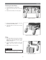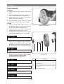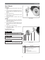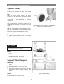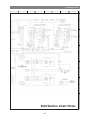
1
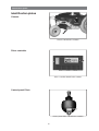
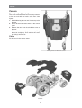
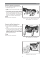
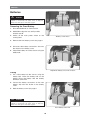
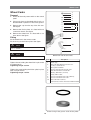
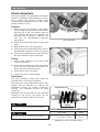
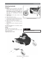
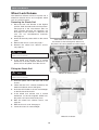
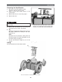
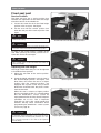
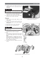
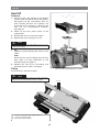
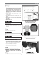
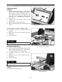
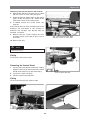
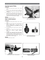
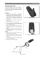
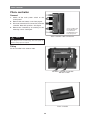
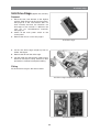
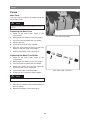
SERVICE MANUAL UK Permobil C300 Power wheelchair How to contact Permobil Permobil BV Zuiddijk 1 5705 CS Helmond Holland Tel: +31 492 598260 Fax: +31 492 598261 E-mail: [email protected] Head Office of the Permobil group Permobil AB Box 120, 861 23 Timrå, Sweden Tel: +46 60 59 59 00. Fax: +46 60 57 52 50 E-mail: [email protected] Produced and published by Permobil AB, Sweden Edition no.3, 2009-06 Order no.: 205206-UK-0 Contents Contents Introduction ....................................................................................................... 5 Identification plates .......................................................................................... 6 Covers................................................................................................................ 8 Batteries........................................................................................................... 10 Front wheels.................................................................................................... 12 Rear wheels..................................................................................................... 13 Support wheels ............................................................................................... 14 Support wheels dampers ............................................................................... 14 Wheel forks ..................................................................................................... 15 Shock absorbers............................................................................................. 16 Slewing brackets ............................................................................................ 17 Wheel lock release ........................................................................................ 18 Plastic rail ................................................................................................... 18 Magnetic wheel lock ................................................................................... 19 Wheel Lock Release Sensor ...................................................................... 20 Drive motor...................................................................................................... 21 Seat elevator ................................................................................................... 22 Manual Raising/Lowering of the Seat elevator ........................................... 22 Removing the Seat elevator ....................................................................... 23 Fixed seat post................................................................................................ 24 Service Position .......................................................................................... 24 Adjusting the Seat Height ........................................................................... 24 Removal ...................................................................................................... 25 Seat tilt ............................................................................................................ 26 CS-seat ........................................................................................................... 27 Corpus-seat .................................................................................................... 28 Control panel pilot+........................................................................................ 30 Seat control panel ....................................................................................... 30 Control panel VSI............................................................................................ 31 Pilot+ controller .............................................................................................. 31 SLS drive stage............................................................................................... 33 Fuses................................................................................................................ 34 Main Fuse .................................................................................................... 34 SLS fuse ...................................................................................................... 35 Fuse for seat/lighting ................................................................................... 35 Control System ............................................................................................... 36 Trouble shooting............................................................................................. 37 Cabling overview VSI ..................................................................................... 40 Cabling overview Pilot+ ................................................................................. 42 Distribution Chart VSI ................................................................................... 44 Distribution Chart Pilot+ ............................................................................... 46 Index ............................................................................................................... 49 4 Introduction Introduction The Service Manual is intended for technical personnel who maintain and repair electric wheelchairs. It is important that anyone who performs maintenance and repairs described in this manual reads and understands the content of this manual so that the work is performed professionally. Always state the chassis number when contacting Permobil to ensure that the correct information is provided. Technical Support In the event of technical problems, you should contact your dealer, or Permobil BV Holland at +31-492 554 010. Spare parts Spare parts must be ordered through your dealer. Warranties All wheelchairs are supplied with a two-year product guarantee. Batteries and charger are supplied with a one-year warranty Maintenance See the information in the Owner’s Manual. 5 Identification plates Identification plates Chassis Chassis identification number. Pilot+ controller Pilot+ controller identification number. Control panel Pilot+ Control panel Pilot+ identification number. 6 Identification plates Control panel VSI Control panel VSI identification number. 7 Covers Covers Removing the Chassis Cover The cover is mounted with hook and loop fastener at the rear and with two knobs at the front. See figure. 1. Move/fold the leg rests out and, if necessary, raise the seat. 2. Switch off the main power switch on the control panel. 3. Remove the two knobs that hold the cover at the front. 4. Release the hook and loop fastener by lifting the cover straight up. Then remove the cover by pulling it backwards. Fitting Fit the cover in the reverse order. Fixing points of the front cover. Covers. 8 Covers Removing the Front Battery Cover The cover is wedged in under the chassis cover. 1. Move/fold the leg rests out. 2. Switch off the main power switch on the control panel. 3. If the chassis cover has not been removed, remove the two knobs that hold it in place at the front. Lift the chassis cover a little at the front so that the front battery cover comes free. Raise the seat if necessary. Remove the front battery cover by lifting it upwards/forwards. Fitting Fit the cover in the reverse order. Lift the chassis cover a little at the front so that the front battery cover comes free. Removing the Rear Battery Cover The cover is fitted with two guide lips. 1. Switch off the main power switch on the control panel. 2. If the chassis cover has not been removed, lift its rear edge so that the rear battery cover comes free. Raise the seat if necessary. Remove the rear battery cover by pressing its guide lips straight out on both sides and then lifting it upwards/backwards. Fitting Fit the cover in the reverse order. Lift the chassis cover a little at the back so that the rear battery cover comes free. Fixing points of the rear cover. 9 Batteries Batteries WARNING Be careful when using metal objects when working with batteries. A short-circuit can easily cause an explosion. Always use safety gloves and safety goggles. Removing the Front Battery 1. Place the wheelchair on a level surface. 2. Move/fold the leg rests out, and if possible, raise the seat lift 3. Switch off the main power switch on the control panel. Battery connections. 4. Remove the front battery cover. See page 9. 5. Disconnect the battery connections. See also the sticker on the battery cover. 6. Lift/pull the battery out of the chassis using the battery belt. Lift/pull the battery out of the chassis. Fitting 1. Lift a new battery into the chassis using the battery belt. Leave the battery belt on the battery. Place the battery with the battery terminals at the front. 2. Connect the battery connections on the new battery. See also the sticker on the battery cover. 3. Refit the battery cover. See page 9. WARNING Be careful when using metal objects when working with batteries. A short-circuit can easily cause an explosion. Always use safety gloves and safety goggles. Front battery removed. 10 Batteries Removing the Rear Battery 1. Place the wheelchair on a level surface. 2. Switch off the main power switch on the control panel. 3. Remove the rear battery cover. See page 9. Battery connections. 4. Disconnect the battery connections. See also the sticker on the battery cover. 5. Lift/pull the battery out of the chassis using the battery belt. Lift/pull the battery out of the chassis. Fitting 1. Lift a new battery into the chassis using the battery belt. Leave the battery belt on the battery. Place the battery with the battery terminals at the rear. 2. Connect the battery connections on the new battery. See also the sticker on the battery cover. 3. Refit the battery cover. See page 9. WARNING Be careful when using metal objects when working with batteries. A short-circuit can easily cause an explosion. Always use safety gloves and safety goggles. Rear battery removed. 11 Front wheels Front wheels Removal 1. Turn off the main power switch on the control panel. 2. Lift the wheelchair chassis and support it on blocks so that the wheel is off the ground. 3. Remove the hubcap (1), bolt (2) and the three washers (3 and 4); see figure. 4. Pull the wheel off the shaft. Use puller 304103-99-0 if the wheel is tight; see figure. Fitting 1. Check that the wheel shaft and rim are undamaged. Clean as necessary to remove dirt and rust. Replace damaged parts. Puller 304103-99-0. 2. Check that the key is firmly attached and undamaged; fit a new key if necessary. 3. Lubricate the shaft with a thin layer of copper paste (Würth 0893800x, Art. no.: 1820540). WARNING Do not use any type of lubrication in the threaded hole in the axle or on the bolt. 4. Fit the wheel onto the axle. The use of hand force only is preferred, but, if need be, carefully use a rubber mallet, whose head diameter is no less than 1.5 inches (38 mm), to ensure that the rim is fully seated upon the motor. NOTE Hitting too hard with a rubber mallet could cause damage to the gear. 1 2 3 5. Mount the three washers (3) and 4) onto the bolt (2) and secure the wheel. Use a torque wrench to tighten the bolt to 33Nm. Install the hub cap (1). See Fig. 13. 4 5 6 Fitting of rim. Pos. NOTE Description The washer (4) should be placed with the most flat side inwards. 1 Hubcap 2 Bolt, ISO 4762 M8x25 10.9 Fe/Zn 5 C2 / Locking coat DIN 267-28 3 Shim washer DIN 988 8 A2 (DB 8x14x0.5 Stainless) 4 Washer, 8 HB 305 Fe/Zn 5 C2 (TBRSB 8,4x26x5) 5 Front wheel 6 Key DIN 6885A 6x6x22 NOTE The bolt must be used once only. Removed bolt is not allowed to be refitted. WARNING Other types of bolts or washers are not to be used. WARNING Do not use any other type of thread lock. 12 Rear Wheels Rear Wheels Removal 1. Switch off the main power switch on the control panel. 2. Lift up and chock up the wheelchair chassis so that the wheel to be removed is free of the ground. 3. Remove the hub cap 1. 4. Remove the nut 2. Apply pressure to the screw 6 using an Allen key. 5. Remove the washer 3, wheel 4, axle 5 and screw 6. Rear Wheel. Fitting 1. Check that the axle and rim are not damaged. If necessary, clean to remove dirt and rust. Replace damaged parts. 2. Fit the wheel on the axle using just your hands. Check that the wheel is fully located on the axle. 3. Fit the screw 6 in the wheel fork. 4. Fit the axle 5, wheel 4, washer 3 and nut 2, and tighten the wheel. 5. Fit the hub cap 1. Tightening torque: 24 Nm. NOTE Screws and nuts must only be used once. Once removed, screws and nuts must therefore never be refitted. WARNING No other type of screws, nuts and washers than those stated here may be used. 1 WARNING 2 3 4 No other type of lock coating or lock liquid may be used. 5 6 Fitting of rim. Pos. 13 Description 1 Hubcap 2 Locking nut, ISO 7040 M6 8 Fe/Zn 5 Cl 3 Washer, ISO 2768-c, 8,5x23x3 4 Rear Wheel 5 Axel, ISO 2768-m Ø15 6 Bolt, ISO 10642, M8x70, 10.9 Fe/Zn 5 C1 Support Wheels & Support Wheel Dampers Support Wheels Support wheels may be fitted in three different positions; low, medium and high. These fitting positions are marked L, M and H. Low With the support wheels fitted in the lower position, low, the wheelchair inclines less before the support wheels meet the ground, but the accessibility of the wheelchair is reduced somewhat. H M L Medium The support wheels are fitted as standard in the middle position, medium. This position suits most users. Support wheels may be fitted in three different positions; low, medium and high. High With the support wheels fitted in the top position, high, the accessibility increases somewhat, but it also means that the wheelchair may incline more before the support wheels meet the ground. Removal 1. Switch off the main power switch on the control panel. 2. Remove the screw. See figure. WARNING Removing the support wheels entails an increased risk of the wheelchair tipping over. The wheelchair must not be driven when the support wheels are not fitted. Fitting 1. Switch off the main power switch on the control panel. 2. Fit the wheel with the screw, washer and nut in the desired position. See figure. Support Wheel Dampers Removal 1. Switch off the main power switch on the control panel. 2. Remove the chassis cover. See page 8. 3. Unscrew and remove the two screws that hold the support wheel damper in place. See figure. Fitting Support wheel damper. Fit the damper in the reverse order. 14 Wheel Forks Wheel Forks 1 Removal 2 3 4 5 1. Switch off the main power switch on the control panel. 2. Lift up and chock up the wheelchair chassis so that the wheel in question is free of the ground. 3. Remove the cap from the top of the link arm. See figure. 8 7 6 4. Remove the friction plate. It is fitted with one screw from above. See figure. 5. Remove the wheel fork. It is fitted with a nut from above. See figure. Fitting 9 Fit the wheel fork in the reverse order. Fit the O-ring on the friction plate. See figure. 10 NOTE Lubricate the O-ring with Lubricant friction brake, Part. no: 1820405 11 NOTE Wheel fork with friction brake. No other type of lubricant than that stated here may be used. Pos. Tighten the nut holding the wheel fork in place with a torque wrench. Tightening torque: 33 Nm. Tighten the screw holding the friction plate in place with a torque wrench. Tightening torque: 15 Nm. Description 1 Plastic plug 2 Bolt, ISO 10642 M8x20 10.9 Fe/Zn 5 C1/ Locking coat DIN 267-28 3 O-ring Ø24.2x3 EPDM 4 Friction plate ISO 2768-m Fe/Zn 12C1 5 Nut, DIN 934 M14x1.5 8Fe/Zn 8C1 6 Bearing, 6002-2RS1 (15x32x9) 7 Circlip, DIN 472 Ø32 8 Spacer, ISO 2768-m Fe/Zn 12C1 (Ø20 h9) 9 Spacer, ISO 2768-m Fe/Zn 12C1 10 Bolt, ISO 2768-m Stainless Lubricant friction brake, Momentum, PRO AA 2/0,025 Fit the O-ring In the groove of the friction plate. 15 Shock Absorbers Shock Absorbers The shock absorbers may be fitted in two different positions, a standard position(suitable for all users) and a position that produces slightly softer suspension(recommended for user’s with a body weight of 150 lbs or less). Removal 1. Raise the seat; seat elevator to the highest position; fixed seat tube to the service position. See page 24. If the seat elevator does not work normally because the batteries are discharged or the actuator is defective, the seat can be raised/lowered manually. See page 22. 2. Switch off the main power switch on the control panel. Shock Absorber 3. Remove the chassis cover. See page 8. 4. Lift up and chock up the wheelchair chassis so that the wheel in question is free of the ground. 5. Unscrew and remove the two screws that hold the shock absorber in place. See figure. Fitting 1. Fit the shock absorber on the chassis with screws and washers. 2. Using screws, washers and nuts, fit the other end of the shock absorber in the position on the link arm that suits the user best. 3. Fit the chassis cover. See page 8. 4. Lower the seat to its normal height. Shock Absorbers fitted in standard position. Adjustment The shock absorber’s spring force should be adjusted to the correct value; see figure. The spring force can be adjusted for various user weights with the adjusting nut. Reduce the adjustment distance for harder suspension; increase the adjustment distance for softer suspension. Adjustment nut Adjustment can be done with the shock absorber mounted in the chassis, but make sure the wheelchair isn’t under influence of any load. NOTE Setting Do not have any load in the wheelchair when adjusting. Adjustment of shock absorber spring User weights NOTE Never adjust the spring to a setting less then 46 mm. Setting 0 - 100 Kg. 48 mm. Above 100 Kg. (standard) 46 mm. Adjustment of shock absorber spring. 16 Slewing brackets Slewing brackets Removal 1. Raise the seat; seat elevator to the highest position; fixed seat tube to the service position. See page 24. If the seat elevator does not work normally because the batteries are discharged or the actuator is defective, the seat can be raised/lowered manually. See page 22. 2. Switch off the main power switch on the control panel. 3. Remove the chassis cover. 4. Lift up and chock up the wheelchair chassis so that the wheel in question is free of the ground. Slewing bracket attachment. 5. Remove the front wheel, see page 12. 6. Remove the lower shock absorber bracket. See page 16. 7. Remove the link arm, it is fitted with screw and washer. For removal of wheel forks and wheels, see the respective chapters. Fitting Fit the link arm in the reverse order. Tighten the screw holding the link arm in place with a torque wrench. NOTE Do not use a Pneumatic impact wrench. Tightening torque: 15 Nm. Removal/fitting of slewing brackets. 17 Wheel Lock Release Wheel Lock Release The wheel lock release consists of a plastic rail, a wheel lock release sensor and a magnetic wheel lock on each drive motor. Removing the Plastic Rail 1. Raise the seat; seat elevator to the highest position; fixed seat tube to the service position. See page 24. If the seat elevator does not work normally because the batteries are discharged or the actuator is defective, the seat can be raised/lowered manually. See page 22. 2. Switch off the main power switch on the control panel. 3. Remove the chassis cover. See page 7. If the wheel lock release arm is moved backwards on the left magnetic wheel lock, the plastic rail can be pulled out of the chassis. 4. Remove the wheel lock release sensor, see page 20. NOTE Before removing the plastic rail, make sure the wheel lock release sensor is removed. 5. If the wheel lock release arm is moved backwards on the left magnetic wheel lock, the plastic rail can be pulled out of the chassis. Fitting the Plastic Rail Wheel lock release sensor. NOTE Before inserting the plastic rail, make sure the wheel lock release sensor is removed. 1. Insert the plastic rail on the right side of the chassis. 2. Check that the rail is correctly located by the wheel lock release sensor. See figure. 3. Push the rail in further so that its end emerges on the left side of the chassis. 4. If the wheel lock release arm is moved backwards on the left magnetic wheel lock, the plastic rail can be moved into place. 5. Refit the wheel lock release sencor, see page 20. 6. Refit the chassis cover. See page 7. 7. Lower the seat to its normal height. Wheel lock release 18 Wheel Lock Release Removing the Magnetic wheel lock. 1. Raise the seat; seat elevator to the highest position; fixed seat tube to the service position. See page 24. If the seat elevator does not work normally because the batteries are discharged or the actuator is defective, the seat can be raised/lowered manually. See page 22. 2. Switch off the main power switch on the control panel. 3. Remove the chassis cover. See page 8. 4. Disconnect the electrical connection of the magnetic wheel lock. See figure. The electrical connections of the wheel locks are positioned on the inside of the chassis, on each side of the seat lift/seat post. Magnetic wheel lock. 5. Unscrew and remove the three screws that hold the wheel lock in place. See figure. Fitting the Magnetic Wheel lock Fit the magnetic wheel lock in the reverse order. Fit the magnetic wheel lock with the release arm facing upwards. The magnetic wheel lock is fitted with three screws 19 Wheel Lock Release Removing the wheel lock release sensor. 1. Raise the seat; seat elevator to the highest position; fixed seat tube to the service position. See page 24. If the seat elevator does not work normally because the batteries are discharged or the actuator is defective, the seat can be raised/lowered manually. See page 22. 2. Switch off the main power switch on the control panel. 3. Remove the chassis cover. See page 8. 4. Disconnect the electrical connection of the wheel lock release sensor, it´s positioned on the top of the front battery. Wheel lock release sensor is fitted with two screws. 5. Remove the wheel lock release sensor. It is fitted with two screws. See figure. 6. Remove the plate fitted on the wheel lock sensor. It is fitted with two screws and nuts. Fitting the Wheel Lock Release Sensor Fit the wheel lock release sensor in the reverse order. Wheel lock release sensor. 20 Drive Motor Drive Motor Removal 1. Raise the seat; seat elevator to the highest position; fixed seat tube to the service position. See page 24. If the seat elevator does not work normally because the batteries are discharged or the actuator is defective, the seat can be raised/lowered manually. See page 22. 2. Switch off the main power switch on the control panel. 3. Remove the chassis cover. See page 8. 4. Chock up the relevant side of the wheelchair. 5. Remove the front wheel on the relevant side. See page 12. The electrical connections of the wheel locks and drive motors are positioned on the inside of the chassis, on each side of the seat lift/seat post. 6. Disconnect the electrical connection for the drive motor and the magnetic wheel lock. The connections are positioned on the inside of the chassis, on each side of the seat lift/seat post. 7. Run the connection cables out through the chassis’ cable duct. See figure. 8. Remove the four screws that hold the drive motor’s gear and the support wheel brackets in place. Fitting Fit the drive motor in the reverse order. Drive motor and gear. Drive motor and gear. 21 Seat elevator Seat elevator Manual Raising/Lowering of the Seat elevator (Applies to Corpus II and PS seats) If the seat lift does not work normally because the batteries are discharged or the actuator is defective, the seat can be raised/lowered manually. 1. Switch off the main power switch on the control panel. 2. Remove the cushion and plastic plugs from the seat. 3. Raise/lower the seat using the seat lift crank supplied. See figure. Corpus II Seat WARNING Drills must not be used in connection with manual operation of the seat lift. There is a risk of damage to materials. 22 Seat elevator Removing the Seat Elevator 1. Raise the seat to the highest position manually. See the previous page. 2. Switch off the main power switch on the control panel. 3. Remove the chassis cover. See page 8. 4. Remove the seat. NOTE The seat is heavy. Two people should therefore lift it. Be careful with the cabling. VSI, the electrical connections of the seat elevator are positioned on the inside of the chassis, on each side of the seat elevator. 5. Remove the seat elevator by unscrewing and removing the four screws. See figure. 6. VSI Divide the seat elevator cabling at the contact on the cables. Remove the cabling for the halfspeed sensor. Pilot+ Disconnect the seat elevator cabling from the SLS drive stage. For more information on the SLS drive stage, see page 35. 7. Lift the seat elevator straight up out of the chassis. Fitting Fit the seat elevator in the reverse order. The seat elevator is fitted with four screws. 23 Fixed seat Post Fixed seat post Service Position The fixed seat post has a service position that facilitates the adjustment of the fixed seat height and other service on the wheelchair. 1. Loosen the screw that locks the fixed height position of the seat post. See figure. 2. Lift the seat until the service position lock holds the seat post in the service position. See figure. NOTE Because the seat is heavy, it should be lifted by two persons. Be careful with the cabling. Screw that locks the fixed height position. WARNING The seat must not be subjected to load and the wheelchair must not be driven with the fixed seat tube in the service position. To return to the normal position, carefully lift the seat while pressing the service position lock in. Lower the seat to the set height. WARNING Before pressing the service position lock in, lift up and hold the seat in a steady grip, if not, the seat will fall down which can cause personal injury Adjusting the Seat Height The length of the fixed seat post can be adjusted to six different fixed positions 1. Adjust the seat tube to the service position. See above. 2. Screw the height adjustment screw in place in the desired height position. See figure. The three holes, that raises the seat to a higher position than the standard position, are equipped with a plastic screw. If any of these three holes should be used, the plastic screws must be removed. When the seat is raised to a higher position than the standard position it is recommended that the wheelchair’s control system be reprogrammed with the “Max Forward Speed” parameter set to 75%. This is important especially for user’s with a body weight that exceeds 100 Kg. More information about programming the wheelchair’s control system is found on page 36. Service position lock. WARNING If the seat is raised higher than the standard position, it is recommended that the wheelchair’s control system be reprogrammed with the “Max Forward Speed” parameter set to 75%. This is important especially for user’s with a body weight that exceeds 100 Kg. Height adjustment screw in standard position. 24 Fixed Seat Post 3. Carefully lift the seat while pressing the service position lock in. Lower the seat to the set height. WARNING Before pressing the service position lock in, lift up and hold the seat in a steady grip, if not, the seat will fall down witch can cause personal injury 4. Turn the seat so that the height adjustment screw ends up in its groove. See figure. 5. Tighten the screw that locks the fixed height position of the seat tube. See figure. Turn the seat so that the height adjustment screw ends up in its groove. Removal 1. Switch off the main power switch on the control panel. 2. Lift the seat until the service position lock holds the seat post in the service position, see page 24. 3. Remove the chassis cover. See page 8. 4. Remove the seat, see page 27or 28. NOTE Because the seat is heavy, it should be lifted by two persons. Be careful with the cabling. 5. Remove the fixed seat post by unscrewing and removing the four screws, see figure. 6. VSI If the wheelchair is equipped with seat tilt, divide the seat tilt cabling at the contact on the cables. Fixed Seat post. Pilot+ If the wheelchair is equipped with seat tilt, disconnect the seat tilt cabling from the SLS drive stage. For more information on the SLS drive stage, see page 35. 7. Lift the fixed seat post straight up out of the chassis. The fixed seat post is fitted with four screws. 25 Innehåll Seat tilt Seat tilt Removal 1. Raise the seat; seat elevator to the highest position; fixed seat tube to the service position. See page 24. If the seat elevator does not work normally because the batteries are discharged or the actuator is defective, the seat can be raised/lowered manually. See page 22. 2. Switch off the main power switch on the control panel. 3. Remove the chassis cover. See page 8. 4. Remove the seat, see page 27 or 28. NOTE Because the seat is heavy, it should be lifted by two persons. Be careful with the cabling. 5. VSI Divide the seat tilt cabling at the contact on the cables. Pilot+ Disconnect the seat tilt cabling from the SLS drive stage. For more information on the SLS drive stage, see page 35. 6. Remove the seat tilt by unscrewing and removing the four screws. See figure. The seat tilt is fitted with four screws. Fitting Fit the seat tilt in the reverse order. NOTE Make sure you are using the correct holes on the seat tilt when fitting it on the seat elevator/Fixed seat post, see figure. 1. 2. 3. 12 3 Used on seats with seat depth extension. Used on standard seats Not used on this chassis 26 CS-seat CS-seat Removal 1. Raise the seat; seat elevator to the highest position; fixed seat tube to the service position. See page 24. If the seat elevator does not work normally because the batteries are discharged or the actuator is defective, the seat can be raised/lowered manually. See page 22. 2. Switch off the main power switch on the control panel. 3. If needed, remove the control panel, see below. 4. Remove the four screws from under beneath, see figure. 5. Remove the seat. The seat is fitted with four screws. The Legrest unit is fitted with four screws with washers and nuts. NOTE Because the seat is heavy, it should be lifted by two persons. Be careful with the cabling. 6. If needed, remove the leg rest unit, it is fitted with four screws with washers and nuts, see fig. Fitting Fit the seat in the reverse order. NOTE Always use the center holes on the leg rest unit when fitting it on the Seat elevator/Fixed seat post. Use the center holes on the leg rest unit when fitting it on the seat lift/fixed seat post. Use the front holes on the seat when fitting it on the leg rest unit. NOTE Always use the front holes on the seat when fitting it on the leg rest unit. Removing the Control Panel 1. Cut the wiring bundle tie holding the cabling together. Take note of the location of the wiring bundle tie for purposes of later remounting. 2 2. Loosen the knob (1), see figure. 3. Pull the Control Panel forwards. Fitting Fit the Control Panel in the reverse order. Removing the Control Panel bracket 1 1. Remove the three screws (2) holding the bracket. Fitting The Control Panel bracket. Fit the Control Panel bracket in the reverse order. 27 Corpus-seat Corpus-seat Removal 1. Raise the seat; seat elevator to the highest position; fixed seat tube to the service position. See page 24. If the seat elevator does not work normally because the batteries are discharged or the actuator is defective, the seat can be raised/lowered manually. See page 22. 2. Switch off the main power switch on the control panel. 3. Remove the cushion from the seat. 4. Remove the seat plate. It’s mounted using two screws. The seat plate is fitted with two screws. Removing seat on chassis without seat tilt 5. If needed, remove the control panel, see page 30. 6. Remove the four screws holding the seat, see figure. 7. Remove the seat. NOTE Because the seat is heavy, it should be lifted by two persons. Be careful with the cabling. On chassis without seat tilt, the seat is fitted with two screws on each side. Removing seat and seat tilt on chassis with seat tilt 5. Switch on the main power switch on the control panel. Tilt the seat approx. 20°. Switch off the main power switch on the control panel. 6. If needed, remove the control panel, see page 30. 7. Remove the four screws holding the seat, see figure. 8. Remove the seat. NOTE Because the seat is heavy, it should be lifted by two persons. Be careful with the cabling. Fitting Fit the seat in the reverse order. On chassis with seat tilt, the seat is fitted with four screws. 28 Corpus-seat Removing seat only on chassis with seat tilt 6. Remove the seat tilt crush protection, it´s fitted with two screws on each side, see figure. 7. Switch on the main power switch on the control panel. Tilt the seat approx. 20°. Switch off the main power switch on the control panel. 8. If needed, remove the control panel, see page 30. If the seat tilt does not work normally because the batteries are discharged or the actuator is defective, the actuators front bracket must be removed, see figure. 9. Remove the four screws holding the seat. If needed, tilt the seat a little to get access to all screws. The crush protectors are fitted with two screws on each side. 10. Remove the seat. NOTE Because the seat is heavy, it should be lifted by two persons. Be careful with the cabling. Fitting Fit the seat in the reverse order. Removing the Control Panel 1. Cut the wiring bundle tie holding the cabling together. Take note of the location of the wiring bundle tie for purposes of later remounting. Front actuator bracket. 2. Loosen the screw, see figure. 3. Pull the Control Panel forwards. Fitting Fit the Control Panel in the reverse order. The seat is fitted with four screws. The control panel bracket. 29 Control panel Pilot+ & Seat control panel Control panel Pilot+ Removal 1. Switch off the main power switch on the control panel. 2. Disconnect the control panel cable by pulling the connector at the rear of the control panel straight backwards. 3. To remove the control panel, remove the screws holding the common bracket for the control panel and Seat control panel, see figure. Remove the control panel bracket by removing the two screws on the rear of the control panel, see figure. Fitting Fitting is the reverse procedure. The Control panel and Seat control panel bracket. Seat control panel Removal 1. Switch off the main power switch on the control panel. 2. Remove the cover of the Seat control panel by pulling it straight upwards. If the lid is stuck, you can carefully use a screwdriver to pry between the lid and the lower part of the end of the box, see figure. 3. You can now lift the circuit board and cable out of the box. 4. Disconnect the cable from the circuit board by pulling the connector straight upwards, see figure. 5. To remove the control panel, remove the screws holding the common bracket for the control panel and Seat control panel, see figure. Remove the Seat control panel bracket by removing the two screws on the underside of the box, see figure. Note the position of the bracket for refitting. The Control panel and Seat control panel fixings. Fitting Fitting is the reverse procedure. The Seat control panel electrical connector. Removing the Seat control panel lid. 30 Control panel VSI Control panel VSI The VSI control panel is a unit that, in addition to a joystick and control buttons, also contains all other electronics required, including a controller. The control panel and complete cabling are replaced as one unit. Removal 1. Raise the seat; seat elevator to the highest position; fixed seat post to the service position. See page 24. If the seat elevator does not work normally because the batteries are discharged or the actuator is defective, the seat can be raised/lowered manually. See page 22. 2. Switch off the main power switch on the control panel. Control panel VSI 3. Remove the chassis cover. See page 8. 4. Cut off the cable ties that hold the control panel cabling. Note the positions of the cable ties for subsequent fitting. 5. Disconnect the contacts for the drive motors, magnetic wheel locks, any actuators and the batteries. 6. Remove the control panel by unscrewing and removing the two screws on the lower side of the control panel. Fitting 1. Fit the control panel using two screws on the lower side of the control panel. The Control panel fixings. 2. Connect the contacts for the drive motors, magnetic wheel locks, any actuators and the batteries. 3. Fit the cable ties that hold the cabling in the same way as previously. 4. Fit the chassis cover. See page 8.. Control unit VSI 31 Pilot+ controller Pilot+ controller Removal A 1. Switch off the main power switch on the control panel. B 2. Remove the rear battery cover. See page 8. C 3. Disconnect the electrical connections from the controller. Note their positions. See figure. D 4. Remove the controller by unscrewing its two mounting screws. See figure. E A: SLS circuit board B: Left drive motor C: Power feed D: Right drive motor E: Control panel Pilot+ controller cable connections. NOTE Contacts A and E on the output stage have the same function. The cabling from the SLS drive stage and control panel can therefore change places if required. Fitting Fit the controller in the reverse order. The Pilot+ controller is attached with two screws. Pilot+ controller 32 SLS Drive Stage SLS Drive Stage (Applies only to Pilot+) Removal 1. Raise the seat; seat elevator to the highest position; fixed seat post to the service position. See page 24. If the seat elevator does not work normally because the batteries are discharged or the actuator is defective, the seat can be raised/lowered manually. See page 22. 2. Switch off the main power switch on the control panel. 3. Remove the chassis cover. See page 8. SLS Drive stage. 4. Lift the SLS Drive stage straight up from its holder. See figure. 5. Remove the lid from the drive stage. 6. Clip the cable ties that hold the cables and its electrical connections, being attentive to their placement to facilitate subsequent refitting. Fitting Fit the SLS drive stage in the reverse order. SLS Drive stage unattached in its holder. SLS Drive stage. 33 Fuses Fuses Main Fuse The main fuse is located in its holder inside the front battery cover. NOTE If the main fuse blows, there is often a major electrical fault. The cause of the fault should be checked carefully before the fuse is replaced. Replacing the Main Fuse 1. Switch off the main power switch on the control panel. The main fuse holder. 2. Remove the front battery cover. See page 9. 3. Unscrew and disassemble the fuse holder. 4. Replace the fuse. 5. Screw the fuse holder back together. 6. Place the fuse holder on the top of the front battery, at the rear edge of the battery. 7. Refit the front battery cover. See page 9. Replacing the Main Fuse Holder 1. Switch off the main power switch on the control panel. 2. Remove the front battery cover. See page 9. 3. Unscrew and disassemble the fuse holder. 4. Detach the cables from the fuse holder by unscrewing the screws. See figure. 5. Connect the cables to the new holder. Main Fuse cable connection. 6. Fit the fuse and screw the holder together. NOTE Check that the cables are firmly attached. 7. Place the fuse holder in the intended place on the front battery. 8. Refit the front battery cover. See page 9. 34 Fuses Replacing the SLS Fuse (Applies only to Pilot+) The SLS fuse is located in its holder inside the rear battery cover. 1. Switch off the main power switch on the control panel. 2. Remove the rear battery cover. See page 9. 3. Open the cover of the fuse holder by pulling it straight out. 4. Replace the blown fuse. SLS-fuse Replacing Fuses for the Seat/Lighting Replacing the SLS-fuse (Applies only to Pilot+) There are two fuses on the SLS Drive stage, F1 (24V unswitched) and F2 (24V switched). These protect two outlets. One output (24V unswitched) supplies power regardless of if the chair is turned on or off. The other output (24V switched) supplies power only when the chair is turned on. The seat and lighting are normally connected to this outlet. F1 F2 1. Raise the seat to its highest position. To raise it manually, see page 22-24. 2. Switch off the main power switch on the control panel. 3. Remove the rear chassis cover; see page 8. 4. Lift the SLS Drive stage straight up from its holder; see page 29. 5. Remove the lid from the drive stage. 6. Replace the blown fuse. 7. Refit the lid to the box. F1: 24V unswitched 15A. F2: 24V switched 15A Seat/Lighting. 8. Place the SLS Drive stage in its holder. 9. Refit the covers; see page 8. 35 Control System Control System The wheelchair's control system can be programmed in order to optimize the performance of the wheelchair while also maintaining a high level of safety, regardless of other settings and options on the wheelchair. The control system can also be programmed in order to make adjustments needed for a specific user. Standard parameter files can be downloaded from the Permobil website, www.permobil.com. To get more information about programming the control system, see the PC-programmer’s technical manual (Order.no: 205009-UK-0). The chart below shows the standard parameter files that are available. Availible standard parameter files C300 Pilot+ C300 VSI Basic C300 VSI Advanced WARNING If the seat is raised higher than the standard position on wheelchairs with fixed seat post, it is recommended that the wheelchair’s control system be reprogrammed with the “Max Forward Speed” parameter set to 75%. This is important especially for user’s with a body weight that exceeds 100 Kg. 36 Trouble Shooting Guide Trouble Shooting Guide The troubleshooting guide below describes a number of events that can arise when you use your wheelchair, as well as providing suggestions for solutions. Note that this guide does not describe all the possible events that can arise, and you should always get in touch with your service contact or Permobil when you are unsure EVENT The wheelchair does not start. POSSIBLE CAUSE SOLUTION Batteries discharged. Charge the batteries. The cable connection to the conttrol panel has become loose. Attach the cable to the control panel. Main fuse blown. See page 34. Battery charger connected. Terminate the charging and remove the charging cable from the charging outlet. Wheel lock release activated. Reset the wheel lock release. Wheelchair locked Unlock the wheelchair. See Owner´s manual. Battery voltage indicator on the control panel rapidly blinking and the wheelchair can not be driven. Fault indicated in the drive electronics. See pages 38-39. Battery voltage indicator on the control panel blinking once every 2.5 seconds and the wheelchair can not be driven. The control system is in Sleep Mode. Switch the start button on the control panel off and on again. The wheelchair stops while being driven. The cable connection to the control panel has become loose. Atttach the cable to the control panel. The wheelchair can only be driven with reduced speed. Seat tilt or seat lift raised to high. Lower seat lift or seat tilt. See Owner´s manual. Main fuse blown. Change Main Fuse See page 34. The wheelchair can not be driven. Applies for electrical seat lift or seat tilt only. The wheelchair will not charge. 37 Trouble Shooting Guide Error signals - Battery voltage indicator 10 Every time the wheelchair is started up, a check is performed on parts of the wheelchair’s electronics. If any faults have arisen in these parts, this is shown on the control panel’s battery voltage indicator by one or more blinking lights. 9 Constant light 4 Everything is in order. How many lights are lit, depends upon how much voltage there is in the batteries. With fully charged batteries, all lights are lit. 3 8 7 6 5 2 1 Pilot+ battery voltage indicator Slowly blinking red lights The batteries need to be charged immediately. Rapidly blinking, 1 - 10 lights Error signals, an error has arisen and the wheelchair can not be driven. Error signals The number of blinking lights indicate what the problem could be. – Note the number of blinking lights. – Turn off the wheelchair. – Turn the wheelchair back on again. – If the error persists, count the number of blinking lights, check possible causes and solutions in the table on the adjoining page. 1 2 3 4 5 6 7 8 9 10 VSI battery voltage indicator. NOTE Possible error signals on the battery voltage indicator are not displayed while the wheelchair is being driven, they only first appear the next time the wheelchair is restarted. WARNING The remedying of errors that are indicated via the battery voltage indicator must be performed by a person with sufficient expertise to be able to perform such in a professional manner. Always contact an authorized serviceman when in doubt. 38 Trouble Shooting Guide CAUSE High battery voltage Failure in wheel lock circuit Fault in electronics Fault in the control panel Charger connected Short circuit right drive motor Open circuit, right drive motor Short circuit left drive motor Open circuit, left drive motor Low battery voltage SOLUTION Green Check the battery and the connections between the battery and the control unit. 9 Check the connections to the magnetic wheel lock. 10 Green 8 Green 7 Orange 6 Orange 5 Orange 4 Orange 3 Red 2 Red 1 Red Check the contacts to the output stage. If the fault persists, change the output stage. Make sure the joystick isn’t actuated at switch-on, change the control panel. Remove the charge plug from the charge socket on the control panel. Check the drive motor connections and cable. Check the connection to the right drive motor. Check the drive motor connections and cable. Check the connection to the left drive motor. Check the condition of the battery. Check the connection between the battery and the control unit. Example: Lights 1-7, 3 red and 4 orange, blinking rapidly upon start-up and the wheelchair can not be driven. Cause: Fault in the control panel. Solution: Make sure the joystick isn’t actuated at switch-on, change the control panel. 39 Cabling overview 1 2 3 A B C D E F 40 4 Cabling overview 5 6 7 8 A B C D E F Cabling overview VSI 41 Cabling overview 1 2 3 A B C D E F 42 4 Cabling overview 5 6 7 8 A B C D E F Cabling overview Pilot+ 43 Distribution Chart 1 2 3 A B C D E F 44 4 Distribution Chart 5 6 7 8 A B C D E F Distribution Chart VSI 45 Distribution Chart 1 2 3 A B C D E F 46 4 Distribution Chart 5 6 7 8 A B C D E F Distribution Chart Pilot+ 47 Notes 48 Index Index B M Batteries ............................................ 10 Magnetic wheel lock ........................ 19 C P Cabling overview VSI ........................ 40 Cabling overview Pilot+ .................. 42 Corpus-seat........................................ 28 Control panel Pilot+ ........................ 30 Control panel VSI ............................ 31 Control System ................................ 36 Covers ................................................ 8 CS-seat .............................................. 27 Pilot+ controller .............................. 31 R Rear wheels ...................................... 13 S Distribution Chart Pilot+ .................. 46 Distribution Chart VSI ...................... 44 Drive motor ...................................... 21 Seat elevator .................................... 22 Seat tilt .............................................. 26 Shock absorbers ............................ 16 Slewing brackets .............................. 17 SLS drive stage ................................ 33 Support wheels ................................ 14 Support wheels dampers ................ 14 F T Fixed seat post ................................ 24 Front wheels .................................... 12 Fuses ................................................ 34 Trouble shooting ..............................37 I Wheel forks ...................................... 15 Wheel lock release .......................... 18 D W Identification plates ............................ 6 Introduction ........................................ 5 49 Order no: 205206-UK-0